


 Loading...
1747-SDN
DeviceNet Scanner
Module
Catalog Number
1747-SDN, Series C
User Manual
Important User Information |
Solid state equipment has operational characteristics differing from those of |
|||||||
|
||||||||
|
electromechanical equipment. Safety Guidelines for the Application, |
|||||||
|
Installation and Maintenance of Solid State Controls (publication SGI-1.1 |
|||||||
|
available from your local Rockwell Automation sales office or online at |
|||||||
|
http://literature.rockwellautomation.com) describes some important |
|||||||
|
differences between solid state equipment and hard-wired electromechanical |
|||||||
|
devices. Because of this difference, and also because of the wide variety of |
|||||||
|
uses for solid state equipment, all persons responsible for applying this |
|||||||
|
equipment must satisfy themselves that each intended application of this |
|||||||
|
equipment is acceptable. |
|||||||
|
In no event will Rockwell Automation, Inc. be responsible or liable for |
|||||||
|
indirect or consequential damages resulting from the use or application of |
|||||||
|
this equipment. |
|
|
|||||
|
The examples and diagrams in this manual are included solely for illustrative |
|||||||
|
purposes. Because of the many variables and requirements associated with |
|||||||
|
any particular installation, Rockwell Automation, Inc. cannot assume |
|||||||
|
responsibility or liability for actual use based on the examples and diagrams. |
|||||||
|
No patent liability is assumed by Rockwell Automation, Inc. with respect to |
|||||||
|
use of information, circuits, equipment, or software described in this manual. |
|||||||
|
Reproduction of the contents of this manual, in whole or in part, without |
|||||||
|
written permission of Rockwell Automation, Inc., is prohibited. |
|||||||
|
Throughout this manual, when necessary, we use notes to make you aware |
|||||||
|
of safety considerations. |
|||||||
|
|
|
|
|
|
|
|
|
|
|
|
|
|
|
|
|
Identifies information about practices or circumstances that can cause |
|
WARNING |
|||||||
|
|
an explosion in a hazardous environment, which may lead to personal |
||||||
|
|
|
|
|
|
|
|
|
|
|
|
|
|
|
|
|
injury or death, property damage, or economic loss. |
|
|
|
|
|
|
|
|
|
|
|
|
|
|
|
|
|
|
|
|
|
|
|
|
|
|
|
|
|
|
|
|
|
|
|
Identifies information that is critical for successful application and |
|
IMPORTANT |
|
||||||
|
|
understanding of the product. |
||||||
|
|
|
|
|
|
|
|
|
|
|
|
|
|
|
|
|
|
|
|
|
|
|
|
|
|
Identifies information about practices or circumstances that can lead |
|
ATTENTION |
|
||||||
|
|
to personal injury or death, property damage, or economic loss. |
||||||
|
|
|
|
|
|
|
|
|
|
|
|
|
|
|
|
|
Attentions help you identify a hazard, avoid a hazard, and recognize |
|
|
|
|
|
|
|
|
the consequence |
|
|
|
|
|
|
|
|
|
|
|
|
|
|
|
|
|
|
|
|
|
|
|
|
|
|
|
|
|
|
|
|
|
|
|
Labels may be on or inside the equipment, for example, a drive or |
|
SHOCK HAZARD |
|
||||||
|
|
|
|
|
|
|
|
motor, to alert people that dangerous voltage may be present. |
|
|
|
|
|
|
|||
|
|
|
|
|
|
|
|
|
|
|
|
|
|||||
|
|
|
|
|
|
|
|
Labels may be on or inside the equipment, for example, a drive or |
|
BURN HAZARD |
|
||||||
|
|
|
|
|
|
|
|
motor, to alert people that surfaces may reach dangerous |
|
|
|
|
|
|
|
|
|
|
|
|
|
|
|
|
|
temperatures. |
|
|
|
|
|
|
|
|
|
|
|
|
|
|
|
|
|
|
Rockwell Automation, TechConnect, SLC, SLC 500, RSNetWorx for DeviceNet, RediSTATION, Series 9000, DH+, Data Highway
Plus, RSLogix 500, FLEX I/O, ControlFlash, RSView, PLC-5, PanelView, RSLinx Classic, are trademarks of Rockwell Automation,
Inc.
Trademarks not belonging to Rockwell Automation are property of their respective companies.

Summary of Changes
The information below summarizes the changes to this manual since the last publication.
To help you find new and updated information in this release of the manual, we have included change bars as shown to the right of this paragraph.
This manual contains this updated information.
Topic |
Page |
|
|
The length of the M0 and M1 files |
64 |
|
|
Numeric code 65 for normal operation when |
91 |
AutoScan is enabled was added |
|
|
|
DeviceNet explicit messaging chapter was |
Chapter 8 |
added |
|
|
|
AutoScan function chapter was added |
Chapter 9 |
|
|
Information about programming the module |
123…127 |
by using the SLC M0 and M1 files was |
|
added |
|
|
|
Information on the 1747-SDN module’s |
Appendix C |
firmware history was added |
|
|
|
Information about data organization was |
Appendix D |
added |
|
|
|
Information about explicit message program |
Appendix E |
control was added |
|
|
|
Publication 1747-UM655B-EN-P - June 2007

4 Summary of Changes
Publication 1747-UM655B-EN-P - June 2007

Table of Contents
Before You Begin
Planning Your Configuration and
Data Mapping Your Devices
Hardware Setup
Configuring the DeviceNet
Network
Preface
Introduction . . . . . . . . . . . . . . . . . . . . . . . . . . . . . . . . . . . . . 9
Audience . . . . . . . . . . . . . . . . . . . . . . . . . . . . . . . . . . . . . . . 9
The Example Application . . . . . . . . . . . . . . . . . . . . . . . . . . 10
Common Techniques Used in This Manual. . . . . . . . . . . . . . 11
Additional Resources. . . . . . . . . . . . . . . . . . . . . . . . . . . . . . 11
Chapter 1
What This Chapter Contains . . . . . . . . . . . . . . . . . . . . . . . . 13 What You Need to Know . . . . . . . . . . . . . . . . . . . . . . . . . . 13 What Your 1747-SDN Module Does . . . . . . . . . . . . . . . . . . . 14 Communicating with Your Devices . . . . . . . . . . . . . . . . . . . 16 Communicating with Your SLC 500 Processor. . . . . . . . . . . . 18 1747-SDN Module Data Tables . . . . . . . . . . . . . . . . . . . . . . 19 RSNetWorx Software as a Configuration Tool . . . . . . . . . . . . 20 What’s Next? . . . . . . . . . . . . . . . . . . . . . . . . . . . . . . . . . . . . 22
Chapter 2
What This Chapter Contains . . . . . . . . . . . . . . . . . . . . . . . . 23 What You Need to Know . . . . . . . . . . . . . . . . . . . . . . . . . . 23 Beginning the Process . . . . . . . . . . . . . . . . . . . . . . . . . . . . . 24 The Example Network. . . . . . . . . . . . . . . . . . . . . . . . . . . . . 24 What’s Next? . . . . . . . . . . . . . . . . . . . . . . . . . . . . . . . . . . . . 30
Chapter 3
What This Chapter Contains . . . . . . . . . . . . . . . . . . . . . . . . 31 Installing the 1770-KFD Module. . . . . . . . . . . . . . . . . . . . . . 31 Installing the SLC 500 Processor. . . . . . . . . . . . . . . . . . . . . . 32 Installing the ControlNet RS-232 Interface Module . . . . . . . . 35 Installing the 1747-SDN Module. . . . . . . . . . . . . . . . . . . . . . 40 Installing the RediSTATION Operator Interface. . . . . . . . . . . 43 Installing the Series 9000 Photoeye . . . . . . . . . . . . . . . . . . . 44 How Your Network Will Look . . . . . . . . . . . . . . . . . . . . . . . 45 What’s Next? . . . . . . . . . . . . . . . . . . . . . . . . . . . . . . . . . . . . 46
Chapter 4
What This Chapter Contains . . . . . . . . . . . . . . . . . . . . . . . . 47 Installing the Software. . . . . . . . . . . . . . . . . . . . . . . . . . . . . 47 Use RSLinx Software to Configure the DeviceNet Driver . . . . 48 Using RSNetWorx for DeviceNet Software to Configure the 1747-SDN Module Scanlist . . . . . . . . . . . . . . . . . . . . . . . . . . 50 What’s Next? . . . . . . . . . . . . . . . . . . . . . . . . . . . . . . . . . . . . 62
Publication 1747-UM655B-EN-P - June 2007

6 Table of Contents
Communicating with the DeviceNet Network from Another Network
Creating and Running the Example
Application Program
Troubleshooting
DeviceNet Explicit Messaging
AutoScan
Data Map Example
Configuring the M0/M1 Files by Using RSLogix 500 Software
Chapter 5
What This Chapter Contains . . . . . . . . . . . . . . . . . . . . . . . . 63 Additional Resources. . . . . . . . . . . . . . . . . . . . . . . . . . . . . . 64 System Requirements . . . . . . . . . . . . . . . . . . . . . . . . . . . . . 64 Communicating with the DeviceNet Network via
an Ethernet Network . . . . . . . . . . . . . . . . . . . . . . . . . . . . . . 65 Communicate with the DeviceNet Network via
a DH+ Network . . . . . . . . . . . . . . . . . . . . . . . . . . . . . . . . . 73 What’s Next? . . . . . . . . . . . . . . . . . . . . . . . . . . . . . . . . . . . . 78
Chapter 6
What This Chapter Contains . . . . . . . . . . . . . . . . . . . . . . . . 79
Install the Software . . . . . . . . . . . . . . . . . . . . . . . . . . . . . . . 80
Create the Example Application Program . . . . . . . . . . . . . . . 80
Download and Run the Program . . . . . . . . . . . . . . . . . . . . . 82
What’s Next? . . . . . . . . . . . . . . . . . . . . . . . . . . . . . . . . . . . . 87
Chapter 7
Module Status Indicator. . . . . . . . . . . . . . . . . . . . . . . . . . . . 89
Network Status Indicator . . . . . . . . . . . . . . . . . . . . . . . . . . . 90
Numeric Display Code Summary . . . . . . . . . . . . . . . . . . . . . 90
Chapter 8
DeviceNet Explicit Message Instruction Overview. . . . . . . . . 93
DeviceNet Explicit Message (DEM) . . . . . . . . . . . . . . . . . . . 94
Chapter 9
Overview . . . . . . . . . . . . . . . . . . . . . . . . . . . . . . . . . . . . . 103 Implementing AutoScan . . . . . . . . . . . . . . . . . . . . . . . . . . 103 Other Important Information about AutoScan. . . . . . . . . . . 112
Appendix A
What This Appendix Contains . . . . . . . . . . . . . . . . . . . . . . 115
Example Input Mapping Scheme . . . . . . . . . . . . . . . . . . . . 115
Example Output Mapping Scheme. . . . . . . . . . . . . . . . . . . 118
Appendix B
RSLogix 500 I/O Configuration . . . . . . . . . . . . . . . . . . . . . 121 Programming the Module by Using the SLC M0
and M1 Files . . . . . . . . . . . . . . . . . . . . . . . . . . . . . . . . . . . 123
Publication 1747-UM655B-EN-P - June 2007

Table of Contents |
7 |
|
|
1747-SDN Module Firmware
History
Data Organization
Appendix C
Purpose . . . . . . . . . . . . . . . . . . . . . . . . . . . . . . . . . . . . . . 129
Revision 8.002. . . . . . . . . . . . . . . . . . . . . . . . . . . . . . . . . . 129
Revisions 7.005 and 7.006 Known Anomalies . . . . . . . . . . . 129
Revision 6.002. . . . . . . . . . . . . . . . . . . . . . . . . . . . . . . . . . 130
Revision 5.001. . . . . . . . . . . . . . . . . . . . . . . . . . . . . . . . . . 132
Revision 4.026. . . . . . . . . . . . . . . . . . . . . . . . . . . . . . . . . . 132
Appendix D
Understand the Data Organization of the Module . . . . . . . . 133 Upload Input Data from the Module to the SLC Processor. . 134 Download Output Data to the Module . . . . . . . . . . . . . . . . 138
Appendix E
Explicit Message Program Control Using Explicit Message Program Control . . . . . . . . . . . . . . |
143 |
Glossary
Index
Publication 1747-UM655B-EN-P - June 2007

8 Table of Contents
Publication 1747-UM655B-EN-P - June 2007

Preface
Introduction
Audience
This user manual is designed to provide you enough information to get a small example application up and running. Use this manual if you are knowledgeable about DeviceNet and SLC 500 products, but may not have used the products in conjunction. The information provided is a base; modify or expand the examples to suit your particular needs.
The manual contains instructions on configuring a DeviceNet network by using RSLinx and RSNetWorx for DeviceNet software. It also describes how to use the SLC 500 pass-through feature to communicate with the DeviceNet network for adjustment and tuning of network devices via an Ethernet and Data Highway Plus (DH+) network.
The example application demonstrates how to perform control on a DeviceNet network by using an SLC 500 processor and the 1747-SDN module. You use RSLogix 500 programming software to create a ladder logic program to control a photoeye and a RediSTATION operator interface.
|
This user manual should be used in conjunction with the |
|
IMPORTANT |
||
1747-SDN DeviceNet Scanner Module Installation Instructions, |
||
|
||
|
||
|
publication 1747-IN058. The installation instructions contain |
|
|
important information on configuring your scanner. |
|
|
|
This manual is intended for control engineers and technicians who are installing, programming, and maintaining a control system that includes an SLC 500 processor communicating on a DeviceNet network through a 1747-SDN module.
We assume that you:
•are developing a DeviceNet network by using a SLC 500 processor in conjunction with a 1747–SDN module.
•know each of your device’s I/O parameters and requirements.
•understand SLC processor programming and operation.
•are experienced with the Microsoft Windows environment.
•are familiar with RSNetWorx for DeviceNet software.
Publication 1747-UM655B-EN-P - June 2007

10 Preface
The Example Application |
This manual describes how to set up an example application. The |
|
manual provides examples of each step of the setup, with references |
|
to other manuals for more details. |
System Components
We used the following devices and software for the example application. For your own application, substitute your own devices to fit your needs. The recommended configurations in this user manual will help you set up the test system and get it working. Your eventual configuration will depend on your application.
TIP |
If you use different software or fimware versions of these |
|
products, some of your dialogs may appear slightly different |
||
|
||
|
||
|
from those shown in the example. |
Quantity |
Product Name |
Catalog Number |
Series/Revision |
|
|
|
|
Hardware |
|
|
|
|
|
|
|
1 |
SLC 500 modular chassis |
1746-A4, 1746-A7, 1746-A10, |
B |
|
|
1746-A13 |
|
|
|
|
|
1 |
SLC 500 power supply |
1746-P1, 1746-P2, 1746-P3, |
- |
|
|
1746-P4, 1746-P5, 1746-P6 |
|
|
|
|
|
1 |
SLC 5/04 processor |
1747-L541, 1747-L542, |
- |
|
|
1747-L543 |
|
|
|
|
|
1 |
SLC 5/05 processor (Ethernet |
1747-L551, 1747-L552, |
- |
|
network) |
1747-L553 |
|
|
|
|
|
1 |
DeviceNet scanner module |
1747-SDN/B |
- |
|
|
|
|
1 |
ControlNet RS-232 interface |
1747-KFC15 |
B |
|
module |
|
|
|
|
|
|
1 |
DeviceNet quad-tap |
1492-DN3TW |
- |
|
|
|
|
1 |
RediSTATION operator interface |
2705-TxDN1x42x-xxxx |
- |
|
module |
|
|
|
|
|
|
1 |
Series 9000 photoeye |
42GNU-9000 or equivalent |
- |
|
|
|
|
1 |
DeviceNet RS-232 interface |
1770-KFD |
- |
|
module |
|
|
|
|
|
|
1 |
RS-232 cables |
1787-RSCABL/A (personal |
- |
|
|
computer to 1770-KFD) |
|
|
|
|
|
|
DeviceNet dropline or trunk |
1787-PCABL, 1787-TCABL, |
- |
|
cables, as needed |
1787-MCABL |
|
|
|
|
|
Publication 1747-UM655B-EN-P - June 2007
Preface 11
Quantity |
Product Name |
Catalog Number |
Series/Revision |
|
|
|
|
1 |
24V power supply |
Any regulated 24V dc, 8 A |
- |
|
|
|
|
1 |
Personal computer |
IBM-compatible Pentium+ |
- |
|
|
Windows 2000 or later |
|
|
|
|
|
Software |
|
|
|
|
|
|
|
|
RSLogix 500 |
9324-RL0300xxx |
Rev 4.00 |
|
|
|
|
|
RSNetWorx for DeviceNet |
9357-DNETL3 |
Rev 2.22 |
|
|
|
|
|
RSLinx |
9355-WAB |
Rev 2.10 |
|
|
|
|
Common Techniques Used
in This Manual
The following conventions are used throughout this manual:
•Bulleted lists provide information, not procedural steps.
•Numbered lists provide sequential steps.
TIP |
This symbol identifies helpful tips. |
|
|
|
|
Additional Resources
These documents contain additional information concerning related Rockwell Automation products.
Resource |
Description |
1747-SDN DeviceNet Scanner Module |
Provides information on installing |
Installation Instructions, publication 1747-IN058 |
and connecting the module. |
|
|
ControlFlash Firmware Upgrade Kit Quick Start, |
Provides instructions on using the |
publication 1756-QS105 |
ControlFlash utility to upgrade the |
|
firmware. |
|
|
Getting Results with RSLogix 500, publication |
Provides information on RSLogix |
LG500-GR002 |
500 software. |
|
|
Getting Results with RSLinx Classic, publication |
Provides information on RSLinx |
LINX-GR001 |
software. |
|
|
DeviceNet Media Design and Installation Guide, |
Provides information on using |
publication DNET-UM072 |
DeviceNet communication network. |
|
|
Getting Results with RSNetWorx for DeviceNet, |
Provides information on using |
publication DNET-GR001 |
RSNetWorx for DeviceNet |
|
software. |
|
|
DeviceNet RS-232 Interface Module, publication |
Provides information on connecting |
1770-5.6 |
and installing the DeviceNet |
|
RS-232 Interface module. |
|
|
SLC 500 ControlNet RS-232 Interface User |
Provides information about the |
Manual, publication 1747-5.34 |
1747-KFC15 module. |
|
|
Publication 1747-UM655B-EN-P - June 2007

12 Preface
Resource |
Description |
ControlNet Coax Media Planning and Installation |
Provides information on planning |
Guide, publication CNET-IN002 |
and installing ControlNet coax |
|
media systems. |
|
|
RediSTATION operator interface User Manual, |
Provides information on installing |
publication 2705-UM001 |
and using the RediSTATION |
|
operator interface. |
|
|
SLC 500 Module Hardware Style User Manual, |
Provides information on installing, |
publication 1747-UM011 |
wiring, startup, and maintenance of |
|
SLC modular hardware. |
|
|
Quick Start for experienced Users, publication |
Provides information on features, |
1747-10.4 |
setup, configuration, and |
|
communication for the SLC 500 |
|
Ethernet processors. |
|
|
You can view or download publications at http://literature.rockwellautomation.com. To order paper copies of technical documentation, contact your local Rockwell Automation distributor or sales representative.
Publication 1747-UM655B-EN-P - June 2007

Chapter 1
Before You Begin
What This Chapter Contains This chapter provides an overview of communication between the SLC 500 processor and DeviceNet devices via the 1747-SDN module.
The configuration data tables and the RSNetWorx for DeviceNet software dialogs and dialogs used to configure the data tables are also described.
The following table identifies what this chapter contains and where to find specific information.
Topic |
Page |
|
|
What You Need to Know |
13 |
|
|
What Your 1747-SDN Module Does |
14 |
|
|
Communicating with Your Devices |
16 |
|
|
Communicating with Your SLC 500 |
18 |
Processor |
|
|
|
1747-SDN Module Data Tables |
19 |
|
|
RSNetWorx Software as a Configuration |
20 |
Tool |
|
|
|
What’s Next? |
22 |
|
|
What You Need to Know Before configuring your 1747-SDN module, you must understand:
•the data exchange between the an SLC 500 processor and DeviceNet devices through the 1747-SDN module.
•user-configurable 1747-SDN module data tables.
•the role of RSNetWorx for DeviceNet software.
Publication 1747-UM655B-EN-P - June 2007
14 Before You Begin
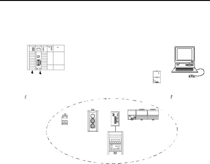
What Your 1747-SDN
Module Does
SLC 500 Modular Chassis
In a typical configuration, the 1747-SDN module acts as an interface between DeviceNet devices and the SLC 500 processor.
Typical DeviceNet Network
Computer with RSNetWorx for DeviceNet Software
SLC 500 |
|
|
|
|
|
|
|
|
1770-KFD PC |
|
|
|
|
||
|
|
|
|
|
|
|
|
|
|
|
|
||||
|
|
|
|
|
|
1747-SDN Interface |
|
|
|
|
|||||
|
|
|
|
|
|
|
|
|
|
||||||
Processor |
|
|
|
|
|
Module |
Communication Module |
|
|
|
|
||||
|
|
|
|
|
|
|
|
|
|
|
|
|
|
|
|
|
|
|
|
|
|
|
|
|
|
|
|
|
|
|
|
|
|
|
|
|
|
|
|
|
|
|
|
|
|
|
|
|
|
|
|
|
|
|
|
|
|
|
|
|
|
|
|
FLEX I/O
Series 9000 Rack
Photoeye RediSTATION
Operator
Interface
DeviceNet
Devices
1305 Drive
The 1747-SDN module communicates with DeviceNet devices over the network to:
•read inputs from a device.
•write outputs to a device.
•download configuration data.
•monitor a device’s operational status.
The 1747-SDN module communicates with the processor in the form of M1/M0 File Transfers and/or Discrete I/O. Information exchanged includes the following:
•Device I/O data
•Status information
•Configuration data
A processor to I/O DeviceNet configuration is shown in the following figure. See the referenced chapters for more information.
Publication 1747-UM655B-EN-P - June 2007

Before You Begin |
15 |
|
|
|
|
|
|
|
|
|
|
|
|
Processor to I/O |
|
|
|
||||||
Input Read by Processor (Chapter 2) |
|
|
|
|
|
|
|
Configure SDN Module (Chapter 4) |
|||||||||||
|
|
|
|
|
|
|
|
|
|
|
|
|
|
|
|
|
|
|
Computer |
|
|
|
|
|
|
|
|
|
|
|
Configure SDN Module (Chapter 4) |
|
|
Running |
|||||
|
|
|
|
|
|
|
|
|
|
|
|
|
RSNetWorx for |
||||||
|
|
|
|
|
|
|
|
|
|
|
|
|
|
|
|
|
|
|
|
|
|
|
|
|
|
|
|
|
|
|
Mapping Table (Chapters 2 and 4) |
|
|
DeviceNet |
|||||
Output Write by |
|
|
|
|
Output Data to Devices |
|
|
Software |
|||||||||||
|
|
|
|
|
|
||||||||||||||
|
|
|
|
|
|
|
|||||||||||||
|
|
|
|
|
|
|
|||||||||||||
|
|
|
|
||||||||||||||||
Processor (Chapter 2) |
|
|
|
|
|
|
|
||||||||||||
|
|
|
|
from SDN (Chapter 2) |
|
|
|
||||||||||||
|
|
|
|
|
|
|
|
|
|
|
|
|
|||||||
|
|
|
|
|
|
|
|
|
|
|
|
|
|
|
|
|
|
|
|
|
|
|
|
|
|
|
|
|
|
|
|
|
|
|
|
|
|
|
|
|
|
|
|
|
|
|
|
|
|
|
|
|
|
|
|
|
|
|
|
|
|
|
|
|
|
|
|
|
|
|
|
|
|
|
|
|
|
|
|
|
|
|
|
|
|
|
|
|
|
DeviceNet Network |
|
|
|
|
|
|
|||
|
|
|
Input Data from |
|
|
|
|
||||||||||||
|
|
|
|
|
|
|
|
||||||||||||
|
|
|
|
|
|
|
|
|
|
|
|
|
|||||||
|
|
|
Device to SDN |
|
|
|
|
|
|
|
|
|
|
||||||
|
|
|
(Chapter 2) |
|
|
|
|
|
|
|
|
|
|
||||||
Input |
|
|
|
|
|
|
|
|
|
|
|
|
|
|
|
|
Output |
||
|
|
|
|
|
|
|
|
|
|||||||||||
Device |
|
|
|
|
|
|
|
|
|
Device |
|||||||||
|
|
|
|
|
|
|
|
|
|
|
|
|
|
|
|
|
|
|
|
The 1747-SDN interface module can also be used to bridge a
DeviceNet network with another network.
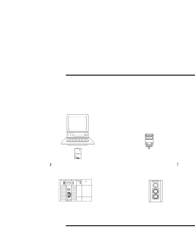
Configuring Devices and Data Collection on Higher-level Networks via
SLC 500/SDN Module
Industrial |
|
|
workstation running |
Laptop computer |
|
RSView software. |
||
running RSNetWorx |
||
|
||
|
software. |
DH+ or Ethernet Network (Chapter 5)
Configuration of device |
|
|
|
using RSNetWorx |
|
|
1747-SDN |
software (Chapter 4). |
|
||
|
Module |
||
|
|
|
|
|
|
|
|
Collection of status or alarm data (Chapter 6).
|
|
|
|
|
|
Target device to |
|
DeviceNet Network |
Source device |
||
be configured. |
|
|
|||
|
|
to collect data. |
|||
|
|
|
|
|
|
|
|
|
|
|
|
|
|
|
|
|
|
Publication 1747-UM655B-EN-P - June 2007

16 Before You Begin
Communicating with Your Devices
The 1747-SDN module communicates with a device via strobe, poll, change of state, and/or cyclic messages. It uses these messages to solicit data from or deliver data to each device. Data received from the devices, or input data, is organized by the 1747-SDN module and made available to the processor. Data received from your SLC 500 processor, or output data, is organized in the 1747-SDN module and sent on to your devices.
|
Throughout this document, input and output are defined from |
|
IMPORTANT |
||
the SLC 500 processor’s point of view. Output is data sent from |
||
|
||
|
||
|
the SLC 500 processor to a device. Input is data collected by the |
|
|
SLC 500 processor from a device. |
All data sent and received on a DeviceNet network is in byte lengths. A device may, for example, produce only two bits of input information. Nevertheless, since the minimum data size on a DeviceNet network is one byte, two bits of information are included in the byte of data produced by the device. In this example (only two bits of input information), the upper six bits are insignificant.
Publication 1747-UM655B-EN-P - June 2007
Before You Begin |
17 |
|
|
Communicating With Other Devices
Different portions of data from a single device can be mapped to separate 1747-SDN memory locations. For example, On/Off values can be mapped to one location, diagnostic values to another. This is known as map segmenting. This concept is illustrated by byte A, stored separately as segments A1 and A2.
1747-SDN Module |
DeviceNet Devices |
Input Data Storage |
|
|
Byte |
A1 |
0 |
B |
1 |
C |
2 |
A2 |
3 |
D |
4 |
E |
5 |
E |
6 |
Output Data Storage |
|
X |
|
Y |
|
Y |
|
Y |
|
Y |
|
Z |
|
Input Data From |
|
DeviceNet Devices |
|
A1 |
A2 |
Input from |
|
the devices |
B |
to the |
|
SLC 500 |
C |
processor. |
|
|
D |
|
E |
Output Data To |
|
DeviceNet Devices |
|
|
X |
Output from |
Y |
the SLC 500 |
|
processor. |
|
|
Z |
Publication 1747-UM655B-EN-P - June 2007

18 Before You Begin
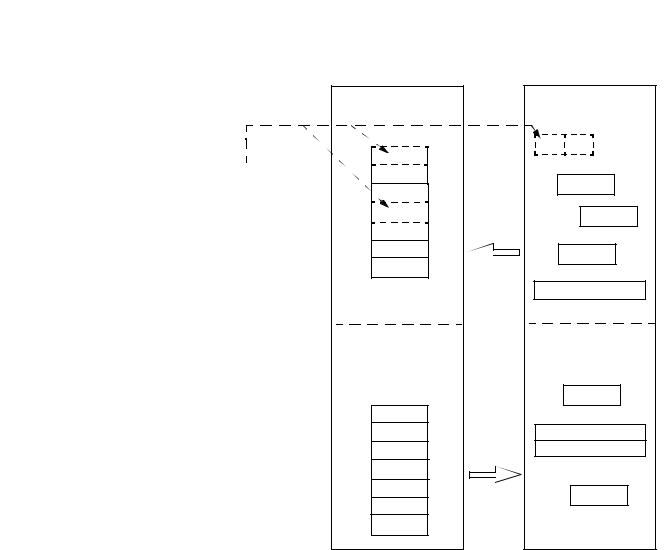
Communicating with Your SLC 500 Processor
The 1747-SDN module does not send data to your processor. Data transferred between the module and the processor must be initiated by the processor. Output data is sent, or written, to the scanner by your processor by placing the data in the M0 file. This data is organized in the scanner, which in turn passes the data on to the scanned devices via strobe, poll, change of state, or cyclic messages.
Data Flow
SLC 500 Processor |
1747-SDN Module |
Discrete Input Image |
|
Internal Input |
|
|
B |
|
|
||
|
Data Storage |
|
||
A1 |
|
|
||
|
A1 |
|
||
|
Discrete I/O |
|
||
M1/M0 File Transfer Data File |
B |
|
||
Transfer |
|
|||
C |
C |
|
||
I/O Map |
|
|||
A2 |
A2 |
|
||
M1 File |
|
|||
|
|
|||
D |
D |
|
||
Transfer |
|
|||
|
|
|||
E |
E |
|
||
(Read) |
Input from |
|||
E |
|
|||
|
E |
the devices. |
||
Discrete Output Image |
|
|
|
|
X |
Discrete I/O |
Internal |
|
|
Output Data |
|
|||
Transfer |
|
|||
M0 Data File |
Storage |
|
||
|
|
|||
|
|
|
||
Z |
I/O Map |
X |
|
|
Y |
|
Y |
|
|
Y |
M0 File |
Y |
|
|
Y |
Transfer |
Y |
Output to |
|
Y |
(Write) |
Y |
||
the devices. |
||||
|
||||
|
|
Z |
|
Publication 1747-UM655B-EN-P - June 2007

Before You Begin |
19 |
|
|
1747-SDN Module Data
Tables
To manage the flow of data between your SLC 500 processor and the network devices, the 1747-SDN module uses the following data tables:
•Scanner configuration table (SCT)
•Scanlist table (SLT)
•Device input data table
•Device output data table
•Device active table
•Device failure table
•Client/Server transaction tables
You can configure the first two of these data tables through RSNetWorx for DeviceNet software.
•Scanner configuration table (SCT)
•Scanlist table (SLT)
These two tables are stored in the 1747-SDN module’s nonvolatile memory and used to construct all other data tables.
Scanner Configuration Table (SCT)
The SCT controls basic information your 1747-SDN module needs to function on your DeviceNet network. It tells your 1747-SDN module:
•if it can transmit and receive input and output data.
•how long it waits after each scan before it scans the devices again.
•when to send out its poll messages.
Scanlist Table (SLT)
The SLT supports I/O updating for each of your devices on the network. It also makes it possible for your 1747-SDN module to make device data available to your SLC processor. The SLT tells your 1747-SDN module:
•which device node addresses to scan.
•how to scan each device (strobe, poll, change of state, cyclic, or any valid combination).
•how often to scan your devices.
•exactly where in each device’s total data to find the desired data.
Publication 1747-UM655B-EN-P - June 2007

20 Before You Begin
•the size of the input data/output data.
•exactly where to map the input or output data for your processor to read or write.
•how your processor reads each device’s input data (M1/M0 file or discrete I/O).
Data Table Information
User-configured Tables |
Data in This Table |
RSNetWorx Software Configuration |
|
|
Dialog |
|
|
|
SCT |
• Basic operation parameters |
1747-SDN module configuration |
|
• I/O communication data |
|
|
(enable/disable) |
|
|
• Interscan delay |
|
|
• Background poll ratio |
|
|
|
|
SLT |
• Device-specific identification data |
Scanlist editor (SLE) |
|
|
|
|
• Data transfer method |
Edit device I/O parameters |
|
• Transmit/receive data size |
|
|
|
|
|
• Input and output data source and |
These values can be configured |
|
destination locations |
automatically through the AutoMap |
|
|
function or manually through the Data Table |
|
|
Map |
|
|
|
RSNetWorx Software as a
Configuration Tool
RSNetWorx for DeviceNet software is used to configure the 1747-SDN module’s data tables. This software tool connects to the 1747-SDN module over the DeviceNet network via a computer RS-232 interface (1770-KFD module) or PC Card (1784-PCD, 1784-PCID, or 1784-PCIDS).
TIP |
RSNetWorx for DeviceNet software can also communicate with |
|
the 1747-SDN module via an Ethernet or Data Highway Plus |
||
|
||
|
||
|
network. |
|
|
See Chapter 5. |
The configuration dialog map below shows the RSNetWorx for DeviceNet dialogs used to configure the 1747-SDN module and the navigation paths between them.
The use of these dialogs is described in Chapter 4.
Publication 1747-UM655B-EN-P - June 2007
Before You Begin |
21 |
|
|
RSNetWorx for DeviceNet Configuration Dialog Map
The main RSNetWorx for DeviceNet dialog.
Double-click the 1747-SDN icon to access the 1747-SDN Interface Module.
Click the Scanlist tab to access the scanlist.
Click Online and select the driver to browse the network.
Click Download to Scanner to download the scanlist.
Select the Input tab and click AutoMap to automatically map input devices.
Select the Output tab and click AutoMap to automatically map output devices.
Double-click the device in the scanlist to edit a device’s I/O parameters.
Publication 1747-UM655B-EN-P - June 2007

22 Before You Begin
What’s Next? |
The remaining sections of this manual provide the following |
|
information: |
|
• Chapter 2 covers the configuration process planning stage |
|
through a data mapping example. |
|
• Chapter 3 describes the hardware setup for the example |
|
application. |
|
• Chapter 4 covers configuration of the DeviceNet network by |
|
using RSNetWorx for DeviceNet software. |
|
• Chapter 5 describes how to configure a DeviceNet network from |
|
another network. |
|
• Chapter 6 describes how to create, download, and run the |
|
example application program. |
|
• Chapter 7 covers the diagnostics provided for troubleshooting |
|
the 1747-SDN module. |
|
• Chapter 8 covers DeviceNet explicit messaging. |
|
• Chapter 9 covers the AutoScan feature. |
Publication 1747-UM655B-EN-P - June 2007

Chapter 2
Planning Your Configuration and Data
Mapping Your Devices
What This Chapter Contains This chapter introduces questions you should ask before configuring your 1747-SDN communication module. In addition, it presents an
example DeviceNet network and I/O data mapping scheme for a photoeye and a RediSTATION operator interface. The following table identifies what this chapter covers and where to find specific information.
Topic |
Page |
|
|
What You Need to Know |
23 |
|
|
Beginning the Process |
24 |
|
|
The Example Network |
24 |
|
|
What’s Next? |
30 |
|
|
What You Need to Know |
To map data via your 1747-SDN communication module, you must |
|
understand the following: |
|
• Network requirements |
|
• Input data mapping |
|
• Output data mapping |
Publication 1747-UM655B-EN-P - June 2007

24 Planning Your Configuration and Data Mapping Your Devices
Beginning the Process
The Example Network
Planning before configuring your 1747-SDN module helps you do these things:
•Use your memory and bandwidth efficiently
•Cater to device-specific needs and requirements
•Give priority to critical I/O transfers
•Leave room for expansion
You need to know what is on your network. You should be familiar with each device’s:
•communication requirements.
•I/O importance and size.
•frequency of message delivery.
At this point in your planning, it is advantageous for you to have some idea of how the network could be expanded. I/O data mapping can be performed automatically by the RSNetWorx software. But when mapping your I/O, you also have the opportunity to allot room for future I/O. This can save time and effort in the future.
For example, RSNetWorx software automatically maps the devices as efficiently as possible, but the result is that multiple devices may share the same word location in memory. However, you can also have the system map the devices such that no two devices share the same memory location by selecting the Dword align option when performing automapping. You can also manually map the devices if you need to assign or reassign them to specific memory locations.
For details, refer to the Help dialogs provided by the RSNetWorx for DeviceNet software. Additional support can be found at the Rockwell Software website: http://www.software.rockwell.com.
The following example illustrates a data mapping plan for a DeviceNet network. Note that even if the mapping is performed automatically by the RSNetWorx software, you must know where the devices are mapped in order to use them in your network.
Publication 1747-UM655B-EN-P - June 2007
Planning Your Configuration and Data Mapping Your Devices |
25 |
|
|
Example Network Devices
This example network has the following devices:
•A computer running RSNetWorx for DeviceNet software
•A 1747-SDN communication module interfacing an SLC 500 processor with the DeviceNet network
•A Series 9000 photoelectric sensor (strobed)
•A RediSTATION operator interface (polled)
|
In the following example, output is data sent to a device from a |
|
IMPORTANT |
||
controller. Input is data collected from a device by a controller. |
||
|
||
|
||
|
|
The system you set up is shown below.
Example Network
Computer running Windows 2000 or later operating system, containing RSNetWorx for DeviceNet software.
Series 9000
Photoelectric Sensor
Node 62 |
|
|
1770-KFD |
Node 9 |
|
|
||||
|
|
|
|
|||||||
|
|
Communication |
|
|
||||||
|
|
|
|
|
|
|
|
|||
|
|
|
|
|
Module |
|
|
|
||
|
|
|
|
|
|
|
DeviceNet Network |
|
|
|
|
|
Node 0 |
|
|
Node 7 |
|
||||
|
|
|
|
|
|
|||||
|
|
|
|
|
|
|
|
|
|
|
|
|
|
|
|
|
|
|
|
|
|
1747-SDN and SLC 500 Processor in
RediSTATION Operator Interface
SLC 1746 Chassis
|
Each end of the DeviceNet trunk cable must be properly |
|
IMPORTANT |
||
terminated with a resistor. Refer to the DeviceNet Media |
||
|
||
|
||
|
Design Installation Guide, publication DNET-UM072, for |
|
|
detailed information. |
|
|
|
Publication 1747-UM655B-EN-P - June 2007
26 Planning Your Configuration and Data Mapping Your Devices
RediSTATION Operator Interface Input and Output Data Mapping
The RediSTATION operator interface has both inputs and outputs that must be mapped. The input byte is mapped to the 1747-SDN module’s M1 file and then to the SLC 500 processor’s input data file. The output byte is mapped to the 1747-SDN module’s M0 file and then to the SLC 500 processor’s output data file.
The mapping procedure, using RSNetWorx for DeviceNet software, is described on page 45.
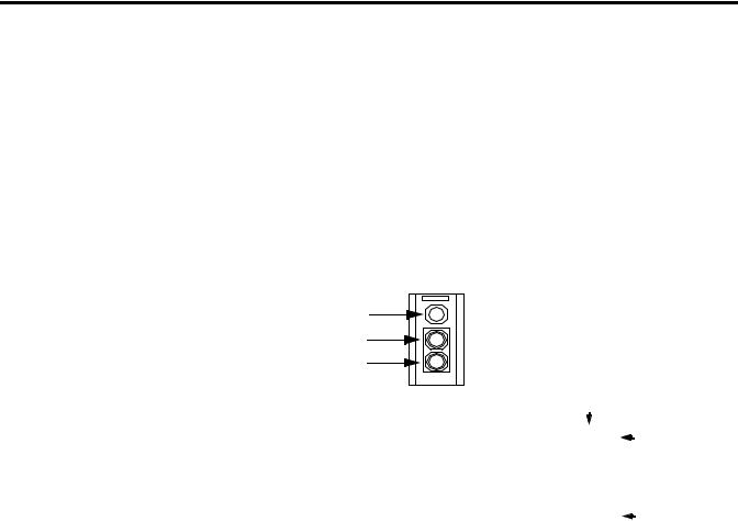
RediSTATION Operator Interface
Indicator Light
Green Start Light
Red Start Light
Two input bits from the RediSTATION operator interface will be mapped: bit 1 for the green Start button and bit 0 for the red Stop button.
Bit 4 of the input byte indicates if the bulb is missing. Start Bit (green button)
The RediSTATION operator interface produces one byte of input data and uses one byte of output data.
Input |
|
|
|
|
|
|
G |
R |
Stop Bit |
|
|
1 byte |
|
|
|||||
|
|
|
|
(red button) |
|||||
|
|
|
|
|
|
|
|
|
|
7 |
6 |
5 |
4 |
3 |
2 |
1 |
0 |
|
|
|
|
|
|
|
|
|
|
|
Status Bit for |
Output |
|
|
|
|
|
|
|
L |
|
|
|
1 byte |
|
|
|
||||
|
|
|
|
|
Indicator Light |
||||
|
|
|
|
|
|
|
|
|
|
|
|
|
|
|
|
|
|
|
|
|
7 |
6 |
5 |
4 |
3 |
2 |
1 |
0 |
|
One output bit for the RediSTATION operator interface’s indicator light (on/off) will be mapped.
In the RediSTATION operator interface’s bits for the red and green buttons and the indicator light status bit:
•1 = ON.
•0 = OFF.
Publication 1747-UM655B-EN-P - June 2007
Planning Your Configuration and Data Mapping Your Devices |
27 |
|
|
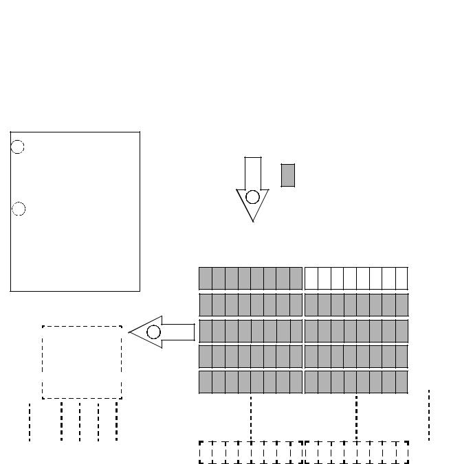
Mapping RediSTATION Input Data for an M1 File Data Table Read
The following is an example of input data mapping for the
RediSTATION operator interface.
RediSTATION Input Byte
What’s Happening?
1
The bits for the RediSTATION operator interfaces’s red and green buttons are mapped into the 1747-SDN module’s M1 data table file.
2The M1 file is then transferred to the SLC 500 processor’s input data file.
Important: The 1747-SDN module only makes the data file available for the processor to read. The 1747-SDN module does not move the data file to the processor.
SLC 500 Processor
Input Data File1
N7:0 |
|
0000 0000 0000 00GR |
|
2 |
|
|
|||
|
|
N7:1 0000 0000 0000 0000
N7:2 0000 0000 0000 0000
|
|
|
|
|
|
|
|
R = Bit for Red Button (STOP) |
|
|
1 byte |
|
|
G |
R |
||
|
|
|
|
G = Bit for Green Button (START) |
||||
|
|
|
|
|
|
|
|
|
|
|
|
|
|
|
|
|
|
= Unused Bits
1
1747-SDN Module M1 File Data Table
G R
Word 0
Word 1
Word 2
Word 3
N7:3 |
|
0000 0000 0000 0000 |
|
Word 4 |
|
|
|||
|
|
N7:4 0000 0000 0000 0000
N7:149 0000 0000 0000 0000 |
Up to |
|
Word 61 |
1This mapping is based upon the example in chapters 4 and 6. The mapping for your system may be different.
Example: The green START button from the RediSTATION operator interface appears in the SLC 500 processor’s input file at address N7:0/1.
The red STOP button from the RediSTATION operator interface appears in the SLC 500 processor’s input file at address N7:0/0.
Publication 1747-UM655B-EN-P - June 2007
28 Planning Your Configuration and Data Mapping Your Devices
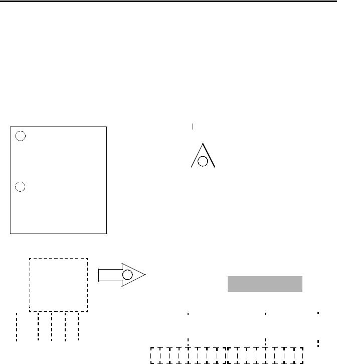
What’s Happening?
1The SLC 500 processor’s output data file containing the indicator light bit for the RediSTATION operator interface is transferred to the 1747-SDN Module’s M0 file data table.
2The M0 file data table is then sent to the RediSTATION operator interface via a polled message from which the RediSTATION operator interface receives its indicator light bit.
PLC-5 Processor
Output Data File1
N8:0 0000 0000 0000 000L
N8:1 0000 0000 0000 0000
N8:2 0000 0000 0000 0000
N8:3 0000 0000 0000 0000
N8:4 0000 0000 0000 0000
Mapping RediSTATION Output Data for an M0 File Data Table Write
The RediSTATION operator interface’s output is mapped to the 1747-SDN module’s M0 file. Within the output byte is a bit for the indicator light. The output data file is then transferred from the SLC 500 processor application to turn the light on or off.
RediSTATION Output Byte
Start/Stop Station Node Address 7
|
|
1 byte |
|
|
|
|
|
|
|
L |
L = Fit for the Station |
|||
|
|
|
|
|
|
|
|
|
Indicator Light |
|||||
|
|
|
|
|
|
|
|
|
|
|
|
|
|
|
|
|
|
|
|
|
|
|
|
|
|
|
|
|
= Unused Bits |
|
|
|
|
|
|
2 |
|
|
|
|
|
|
||
|
|
|
|
|
|
|
|
|
|
|
|
|||
|
|
|
|
|
|
|
|
|
|
|
|
|
||
|
|
|
|
|
|
|
|
|
|
|
|
|
|
|
1747-SDN Module M1 File Data Table
|
|
|
|
|
|
|
|
|
|
|
|
|
|
|
|
|
L |
Word 0 |
|
|
|
|
|
|
|
|
|
|
|
|
|
|
|
|
|
|
|
Word 1 |
|
|
|
|
|
|
|
|
|
|
|
|
|
|
|
|
|
|
|
||
|
|
|
|
|
|
|
|
|
|
|
|
|
|
|
|
|
|
||
|
|
|
|
|
|
|
|
|
|
|
|
|
|
|
|
|
|
Word 2 |
|
|
|
|
|
|
|
|
|
|
|
|
|
|
|
|
|
|
|
||
|
|
|
|
|
|
|
|
|
|
|
|
|
|
|
|
|
|
||
1 |
|
|
|
|
|
|
|
|
|
|
|
|
|
|
|
|
|
Word 3 |
|
|
|
|
|
|
|
|
|
|
|
|
|
|
|
|
|
|
|||
|
|
|
|
|
|
|
|
|
|
|
|
|
|
|
|
|
|||
|
|
|
|
|
|
|
|
|
|
|
|
|
|
|
|
|
|
||
|
|
|
|
|
|
|
|
|
|
|
|
|
|
|
|
|
|
Word 4 |
|
|
|
|
|
|
|
|
|
|
|
|
|
|
|
|
|
|
|
||
|
|
|
|
|
|
|
|
|
|
|
|
|
|
|
|
|
|
||
|
|
|
|
|
|
|
|
|
|
|
|
|
|
|
|
|
|
|
|
|
|
|
|
|
|
|
|
|
|
|
|
|
|
|
|
|
|
|
|
|
|
|
|
|
|
|
|
|
|
|
|
|
|
|
|
|
|
|
|
|
|
|
|
|
|
|
|
|
|
|
|
|
|
|
|
|
|
|
|
|
|
|
|
|
|
|
|
|
|
|
|
|
|
|
|
|
|
|
|
|
|
|
|
|
|
|
|
|
|
|
|
|
|
|
|
|
|
|
|
N8:149 |
0000 0000 0000 0000 |
1 This mapping is based upon the example in chapter 4. The actual mapping for your system may be different.
Up to
Word 149
Example: The RediSTATION operator interface’s indicator light (L) is taken from N8:1/0 in the SLC 500 processor’s output data file.
Publication 1747-UM655B-EN-P - June 2007

Planning Your Configuration and Data Mapping Your Devices |
29 |
|
|
Photoeye Input Data Mapping
The photoelectric sensor (photoeye) inputs are mapped to the 1747-SDN module’s M1 file and then to the SLC 500 processor’s input data file. The procedure for doing this by using RSNetWorx for DeviceNet software is described in chapter 4.
The photoeye has no outputs to map.
Series 9000 Photoeye
Two input bits from the photoeye will be mapped: the status bit and the data bit.
The photoeye produces |
|
|
|
|
|
|
|
|
|
|
|
||||
one byte of input data in |
|
|
|
Status |
|
|
|
|
|||||||
response to the strobe |
|
|
|
Bit |
|
|
|
|
|||||||
message. |
|
|
|
|
|
|
|
|
|
|
|
|
|
|
|
|
|
|
|
|
|
|
|
|
|
|
|
|
|
Data |
|
Input |
|
|
|
|
|
|
|
|
S |
|
D |
||||
|
|
1 byte |
|
|
|
|
|
|
Bit |
||||||
|
|
|
|
|
|
|
|
||||||||
|
|
|
|
|
|
|
|
|
|
|
|||||
|
|
|
|
|
|
|
|
|
|
|
|
|
|
|
|
7 |
6 |
5 |
|
4 |
3 |
2 |
1 |
|
|
0 |
|
|
|
||
Publication 1747-UM655B-EN-P - June 2007

30 Planning Your Configuration and Data Mapping Your Devices
Mapping Photoeye Input Data for an M1 File Data Table Read
What’s Happening?
1The status and data bits from the photoeye are mapped into the 1747-SDN Module’s M1 file data table.
2The M1 file data table is then transferred to the SLC 500 processor’s input data file.
Important: The 1747-SDN module only makes the data available for the processor to read. The 1747-SDN module does not move the data to the processor.
SLC 500 Processor
Input Data File1
N7:0 0000 00SD 0000 0000
N7:1 0000 0000 0000 0000


 2 N7:2 0000 0000 0000 0000
N7:3 0000 0000 0000 0000
N7:4 0000 0000 0000 0000
N7:149 0000 0000 0000 0000
|
|
1 byte |
|
|
S |
D |
|
|
|
|
|
|
|
|
|
= Unused Bits
1
1747-SDN Module M1 File Data Table
|
|
|
|
|
|
S |
D |
|
|
|
|
|
|
|
|
|
|
|
Word 0 |
|
|
RediSTATION |
|
|
|
|
|
||||||||||||
|
|
|
|
|
|
|
|
|
|
|
|
|
|
|
|
|
|
|
|
Word 1
Word 2
Word 3
Word 4
Up to
Word 149
1 This mapping is based upon the examples in chapters 4 and 6. The actual mapping for your system may be different.
Example: The Status bit from the photoeye appears in the SLC 500 processor’s input data file at address N7:0/9.
The Data bit from the photoeye appears in the SLC 500 processor’s input data file at address N7:0/8.
What’s Next? |
Chapter 3 describes how to set up the system hardware for the |
|
example application. |
Publication 1747-UM655B-EN-P - June 2007
Loading...