


 Loading...
Installation Instructions
GuardLogix Controllers
Catalog Numbers 1756-L61S, 1756-L62S, 1756-L63S,
1756-LSP
Topic |
Page |
|
|
|
|
|
|
North American Hazardous Location Approval |
3 |
|
|
|
|
|
|
Environment and Enclosure Information |
4 |
|
|
|
|
|
|
General Safety Information |
4 |
|
|
|
|
|
|
Preventing Electrostatic Discharge |
4 |
|
|
|
|
|
|
Prepare the Chassis |
5 |
|
|
|
|
|
|
Make Sure That You Have All of the Components |
5 |
|
|
|
|
|
|
Install a CompactFlash Card |
6 |
|
|
|
|
|
|
Remove a CompactFlash Card |
7 |
|
|
|
|
|
|
Connect the Battery |
8 |
|
|
|
|
|
|
Install the Controller into the Chassis |
9 |
|
|
|
|
|
|
Check the BAT Status Indicator |
10 |
|
|
|
|
|
|
Check the OK Status Indicator |
10 |
|
|
|
|
|
|
Update the Controller |
11 |
|
|
|
|
|
|
Connect a Serial Cable |
12 |
|
|
|
|
|
|
Choose the Operating Mode of the Controller |
14 |
|
|
|
|
|
|
Replace the Battery |
14 |
|
|
|
|
|
|
General Specifications |
16 |
|
|
|
|
|
|
Environmental Specifications |
17 |
|
|
|
|
|
|
Certifications |
18 |
|
|
|
|
|
|
Additional Resources |
19 |
|
|
|
|
|
|
|
|
|
|
|
|
|
|
2 GuardLogix Controllers
Important User Information
Solid state equipment has operational characteristics differing from those of electromechanical equipment. Safety Guidelines for the Application, Installation and Maintenance of Solid State Controls (publication SGI-1.1 available from your local Rockwell Automation sales office or online at http://literature.rockwellautomation.com) describes some important differences between solid state equipment and hard-wired electromechanical devices. Because of this difference, and also because of the wide variety of uses for solid state equipment, all persons responsible for applying this equipment must satisfy themselves that each intended application of this equipment is acceptable.
In no event will Rockwell Automation, Inc. be responsible or liable for indirect or consequential damages resulting from the use or application of this equipment.
The examples and diagrams in this manual are included solely for illustrative purposes. Because of the many variables and requirements associated with any particular installation, Rockwell Automation, Inc. cannot assume responsibility or liability for actual use based on the examples and diagrams.
No patent liability is assumed by Rockwell Automation, Inc. with respect to use of information, circuits, equipment, or software described in this manual.
Reproduction of the contents of this manual, in whole or in part, without written permission of Rockwell Automation, Inc., is prohibited.
Throughout this manual, when necessary, we use notes to make you aware of safety considerations.
|
|
|
|
|
|
|
|
|
|
|
|
WARNING |
|
|
Identifies information about practices or circumstances that can cause an explosion in |
||||||
|
|
|
|
|
|
|
|
|
|
|
|
|
|
|
|
|
|
|
|
|
a hazardous environment, which may lead to personal injury or death, property |
|
|
|
|
|
|
|
|
|
|
damage, or economic loss. |
|
|
|
|
|
|
|
|
|
|
|
|
|
|
|
|
|
|
|
|
|
|
|
|
|
|
|
|
|
|
|
|
|
|
|
|
|
|
|
|
|
|
|
Identifies information that is critical for successful application and understanding of |
|
IMPORTANT |
|
||||||||
|
|
|
the product. |
|||||||
|
|
|
|
|
|
|
|
|
|
|
|
|
|
|
|
|
|
|
|
|
|
|
|
|
|
|
|
|
|
|
|
|
|
ATTENTION |
|
|
|
Identifies information about practices or circumstances that can lead to personal injury |
|||||
|
|
|
|
|
|
|
|
|
|
|
|
|
|
|
|
|
|
|
|
|
or death, property damage, or economic loss. Attentions help you to identify a hazard, |
|
|
|
|
|
|
|
|
|
|
avoid a hazard, and recognize the consequences. |
|
|
|
|
|
|
|
|
|
||
|
|
|
|
|
|
|
|
|
|
|
|
|
|
|
|
|
|
|
|
||
|
|
|
|
|
|
|
|
|
|
|
|
SHOCK HAZARD |
|
|
|
|
|||||
|
|
|
|
|
|
|
|
|
|
Labels may be on or inside the equipment, for example, a drive or motor, to alert |
|
|
|
|
|
|
|
|
|
||
|
|
|
|
|
|
|
|
|
|
people that dangerous voltage may be present. |
|
|
|
|
|
|
|
||||
|
|
|
|
|
|
|
|
|
||
|
|
|
|
|
|
|
||||
|
|
|
|
|
|
|
|
|
|
|
|
BURN HAZARD |
|
|
|
||||||
|
|
|
|
|
|
|
|
|
|
Labels may be on or inside the equipment, for example, a drive or motor, to alert |
|
|
|
|
|
|
|
|
|
|
|
|
|
|
|
|
|
|
|
|
|
people that surfaces may be dangerous temperatures. |
|
|
|
|
|
|
|
|
|
|
|
|
|
|
|
|
|
|
|
|
|
|
Publication 1756-IN045E-EN-P - October 2009
GuardLogix Controllers 3
North American Hazardous Location Approval
The following information applies when operating |
|
Informations sur l’utilisation de cet équipement en |
|||||||||
this equipment in hazardous locations. |
|
environnements dangereux . |
|||||||||
|
|
|
|||||||||
Products marked “CL I, DIV 2, GP A, B, C, D” are suitable for |
|
Les produits marqués "CL I, DIV 2, GP A, B, C, D" ne conviennent |
|||||||||
use in Class I Division 2 Groups A, B, C, D, Hazardous |
|
qu’à une utilisation en environnements de Classe I Division 2 |
|||||||||
Locations and nonhazardous locations only. Each product is |
|
Groupes A, B, C, D dangereux et non dangereux. Chaque produit |
|||||||||
supplied with markings on the rating nameplate indicating |
|
est livré avec des marquages sur sa plaque d’identification qui |
|||||||||
the hazardous location temperature code. When combining |
|
indiquent le code de température pour les environnements |
|||||||||
products within a system, the most adverse temperature |
|
dangereux. Lorsque plusieurs produits sont combinés dans un |
|||||||||
code (lowest “T” number) may be used to help determine |
|
système, le code de température le plus défavorable (code de |
|||||||||
the overall temperature code of the system. Combinations |
|
température le plus faible) peut être utilisé pour déterminer le |
|||||||||
of equipment in your system are subject to investigation by |
|
code de température global du système. Les combinaisons |
|||||||||
the local Authority Having Jurisdiction at the time of |
|
d’équipements dans le système sont sujettes à inspection par les |
|||||||||
installation. |
|
|
|
autorités locales qualifiées au moment de l’installation. |
|||||||
|
|
|
|
|
|
|
|
|
|
|
|
|
|
|
|
|
EXPLOSION HAZARD |
|
|
|
|
|
RISQUE D’EXPLOSION |
|
WARNING |
AVERTISSEMENT |
|||||||||
|
|
• Do not disconnect equipment |
|
|
• Couper le courant ou s’assurer que |
||||||
|
|
|
|
|
unless power has been removed |
|
|
|
|
|
l’environnement est classé non |
|
|
|
|
|
or the area is known to be |
|
|
|
|
|
dangereux avant de débrancher |
|
|
|
|
|
nonhazardous. |
|
|
|
|
|
l'équipement. |
|
|
|
|
|
• Do not disconnect connections to |
|
|
|
|
|
• Couper le courant ou s'assurer que |
|
|
|
|
|
this equipment unless power has |
|
|
|
|
|
l’environnement est classé non |
|
|
|
|
|
been removed or the area is |
|
|
|
|
|
dangereux avant de débrancher les |
|
|
|
|
|
known to be nonhazardous. |
|
|
|
|
|
connecteurs. Fixer tous les |
|
|
|
|
|
Secure any external connections |
|
|
|
|
|
connecteurs externes reliés à cet |
|
|
|
|
|
that mate to this equipment by |
|
|
|
|
|
équipement à l'aide de vis, loquets |
|
|
|
|
|
using screws, sliding latches, |
|
|
|
|
|
coulissants, connecteurs filetés ou |
|
|
|
|
|
threaded connectors, or other |
|
|
|
|
|
autres moyens fournis avec ce produit. |
|
|
|
|
|
means provided with this |
|
|
|
|
|
• La substitution de composants peut |
|
|
|
|
|
product. |
|
|
|
|
|
rendre cet équipement inadapté à une |
|
|
|
|
|
• Substitution of components may |
|
|
|
|
|
utilisation en environnement de Classe |
|
|
|
|
|
impair suitability for Class I, |
|
|
|
|
|
I, Division 2. |
|
|
|
|
|
Division 2. |
|
|
|
|
|
• S’assurer que l’environnement est |
|
|
|
|
|
• If this product contains batteries, |
|
|
|
|
|
classé non dangereux avant de |
|
|
|
|
|
they must only be changed in an |
|
|
|
|
|
changer les piles. |
|
|
|
|
|
area known to be nonhazardous. |
|
|
|
|
|
|
|
|
|
|
|
|
|
|
|
|
|
|
Publication 1756-IN045E-EN-P - October 2009
4 GuardLogix Controllers
Environment and Enclosure Information
ATTENTION Environment and Enclosure
This equipment is intended for use in a Pollution Degree 2 industrial environment, in overvoltage Category II applications (as defined in IEC 60664-1), at altitudes up to 2000 m (6562 ft) without derating.
This equipment is considered Group 1, Class A industrial equipment according to IEC/CISPR Publication 11. Without appropriate precautions, there may be difficulties with electromagnetic compatibility in residential and other environments due to conducted and radiated disturbances.
This equipment is supplied as open type equipment. It must be mounted within an enclosure that is suitably designed for those specific environmental conditions that will be present and appropriately designed to prevent personal injury resulting from accessibility to live parts.
The enclosure must have suitable flame-retardant properties to prevent or minimize the spread of flame, complying with a flame spread rating of 5VA, V2, V1, V0 (or equivalent) if non-metallic. The interior of the enclosure must be accessible only by the use of a tool. Subsequent sections of this publication may contain additional information regarding specific enclosure type ratings that are required to comply with certain product safety certifications.
In addition to this publication, see:
•Industrial Automation Wiring and Grounding Guidelines, for additional installation requirements, Allen-Bradley publication 1770-4.1.
•NEMA Standards 250 and IEC 60529, as applicable, for explanations of the degrees of protection provided by different types of enclosure.
General Safety Information
ATTENTION
Personnel responsible for the application of safety-related Programmable Electronic Systems (PES) shall be aware of the safety requirements in the application of the system and shall be trained in using the system.
Preventing Electrostatic Discharge
ATTENTION |
This equipment is sensitive to electrostatic discharge, which can cause internal |
|
damage and affect normal operation. Follow these guidelines when you handle |
||
|
||
|
this equipment: |
•Touch a grounded object to discharge potential static.
•Wear an approved grounding wriststrap.
•Do not touch connectors or pins on component boards.
•Do not touch circuit components inside the equipment.
•Use a static-safe workstation, if available.
•Store the equipment in appropriate static-safe packaging when not in use.
Publication 1756-IN045E-EN-P - October 2009
GuardLogix Controllers 5
Prepare the Chassis
Before you install a controller, follow these preliminary steps.
1.Install a ControlLogix chassis (catalog number 1756-A4/B, 1756-A7/B, 1756-A10/B, or 1756-A17/B) according to the ControlLogix Chassis Installation Instructions, publication 1756-IN080.
2.Install one of the following ControlLogix power supplies according to the corresponding installation instructions.
For this power supply Follow the instructions in this publication
1756-PA72
ControlLogix Power Supplies Installation Instructions, publication 1756-IN078.
1756-PB72
1756-PA75
ControlLogix Power Supplies Installation Instructions, publication 1756-IN613.
1756-PB75
1756-PA75R(1)
ControlLogix Redundant Power Supplies Installation Instructions, publication 1756-IN573.
1756-PB75R(1)
(1)A 1756-PSCA2/A redundant power-supply chassis adapter is required for use with redundant power supplies. Refer to ControlLogix Redundant Power Supplies Chassis Adapter Module Installation Instructions, publication 1756-IN590.
Make Sure That You Have All of the Components
A key and the 1756-BA2 battery ship with the 1756-L6xS controller, while the 1756-LSP safety partner ships with the 1756-BA2 battery.
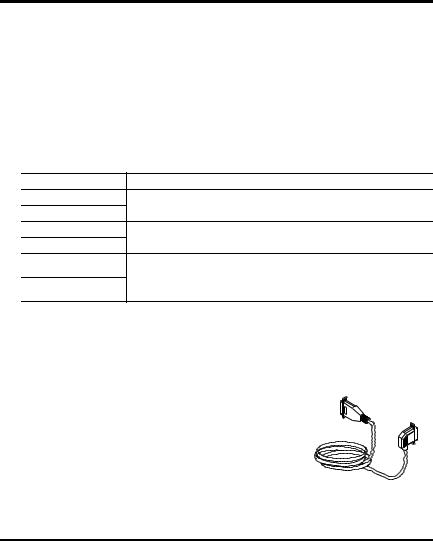
If you want to connect a device to the serial port of the controller (for example, connect a computer to the controller), use a 1756-CP3 serial cable.
You can use a 1784-CF64 or 1784-CF128 CompactFlash card with GuardLogix controllers, firmware revision 18 and later.
IMPORTANT |
You must use a 1756-L6xS primary controller and a 1756-LSP safety partner to |
|
achieve SIL 3/PLe. |
||
|
||
|
|
Publication 1756-IN045E-EN-P - October 2009

6 GuardLogix Controllers
Install a CompactFlash Card
WARNING
When you insert or remove the CompactFlash card an electrical arc can occur. This could cause an explosion in hazardous location installations. Be sure that power is removed or the area is nonhazardous before proceeding.
ATTENTION If you are not sure of the contents of the CompactFlash card, before you install  the card, turn the keyswitch of the controller to the PROG position. Depending on the contents of the card, a power cycle or fault could cause the card to load a different project or operating system into the controller.
1.Turn the keyswitch to the PROG position.
2.Open the door of the controller.
3.Push the CompactFlash latch to the left.
4.Insert the CompactFlash card with the A-B logo pointing left.
5.Release the latch and make sure it slides over the CompactFlash card.
|
COMPACT |
|
FLASH |
DSR-6 |
1-DCD |
2-RXD |
|
RTS-7 |
3-TXD |
CTS-8 |
4-DTR |
N/C-9 |
5-GND |
RS232
1
To
Insert 1
2 |
To Eject |
|
1 + 2 |
|
1 |
UP |
2 |
|
|
BATTERY |
|
DATE |
|
|
1 |
|
2 |
BATTERY |
|
|
PORT |
Publication 1756-IN045E-EN-P - October 2009
Loading...