


Installation Instructions
Bulletin 1494V Variable Depth, Flange Operated Circuit Breaker Operating Mechanisms
For use with Circuit Breakers 140G-G, 140MG-G, 140G-H, 140MG-H, 140G-I, 140MG-I, 140G-J, 140MG-J, 140G-K, 140MG-K, 140G-M, 140MG-M, 140G-N, 140MG-N
(Cat 1494V-M70; 1494V-M71; 1494V-M72)
WARNING: To prevent electrical shock, disconnect from power source before installing or servicing. Follow NFPA 70E requirements. Install in suitable enclosure. Keep free from contaminants.
Installation, adjustments, putting into service, use, assembly, disassembly, and maintenance shall be carried out by suitably trained personnel in accordance with applicable code of practice. In case of malfunction or damage, no attempts at repair should be made. The product should be returned to the manufacturer for repair. Do not dismantle the product.
Table of Contents |
Page |
Enclosure with Handle Cutout |
|
1 - Locate Circuit Breaker Mechanism |
2 |
2 - Handle Installation |
2 |
3 - Cut Connecting Rod |
3 |
4a - 140G-G, 140MG-G, 140G-I, 140MG-I Circuit Breaker Installation |
3 |
4b - 140G-H, 140MG-H, 140G-J, 140MG-J Circuit Breaker Installation |
4 |
4c - 140G-K, 140MG-K Circuit Breaker Installation |
6 |
4d - 140G-M, 140MG-M Circuit Breaker Installation |
7 |
4e - 140G-N, 140MG-N Circuit Breaker Installation |
8 |
5 - Connecting Rod and Mechanism Adjustment Procedure |
11 |
Enclosure without Handle Cutout |
|
6- Locating and Installing Door Catch |
12 |
7- Locating and Drilling Handle Holes |
13 |
8- Circuit Breaker Testing |
14 |
Accessory List |
15 |
2Variable Depth, Flange Operated Circuit Breaker Mechanisms
Enclosure with Handle Cutout
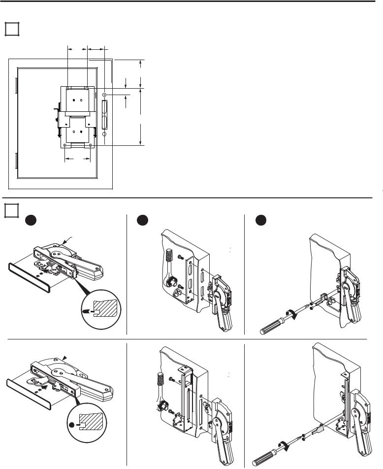
1 |
Locate Circuit Breaker Mechanism |
|
||
|
|
CC1 |
BB |
|
|
|
|
AA |
EE |
|
|
|
|
DD |
|
|
CC2 |
|
|
2 |
Handle Installation |
|
2 |
|
|
1 |
Install gasket. |
|
|
|
|
1494F-M1, -P1 or -S1 |
|
|
Frame |
AA |
BB |
CC1 |
CC2 |
DD |
EE |
|
Size |
|
|
|
|
|
Wire |
|
|
|
|
|
|
|
Bending |
|
|
|
|
|
|
|
Space |
|
|
|
|
|
|
|
|
|
140G-G / 140MG-G |
|
|
|
|
|
|
|
140G-H / 140MG-H |
5/16" |
1 - 41/64" |
3" |
3 - 1/2" |
7 - 1/2" |
6” |
|
140G-I / 140MG-I |
|||||||
|
|
|
|
|
|
||
140G-J / 140MG-J |
|
|
|
|
|
|
|
140G-K / 140MG-K |
29/64” |
1 - 47/64” |
4" |
4 - 1/2" |
9 - 5/16" |
12” |
|
|
|
|
|
|
|
|
|
140G-M / 140MG-M |
4 - 1/2" |
4 - 1/32" |
5" |
5" |
13 - 1/2" |
12” |
|
|
|
|
|
|
|
|
|
140G-N / 140MG-N |
4 - 1/2" |
4 - 1/32" |
5" |
5" |
13 - 1/2" |
12” |
|
|
|
|
|
|
|
|
Install handle and spring bracket. |
3 |
Install defeater lever. |
30-40 lb-in
7-11 lb-in
 1494F-M2 or -S2
60-80 lb-in 

7-11 lb-in
IMPORTANT: Apply grease to O-Ring to retain into handle groove.
Publication 1494V-IN105E-EN-P - September 2014 |
PN-242292 DIR 10000787413 (Version 04) |
Variable Depth, Flange Operated Circuit Breaker Mechanisms |
3 |
Enclosure with Handle Cutout (Cont’d)
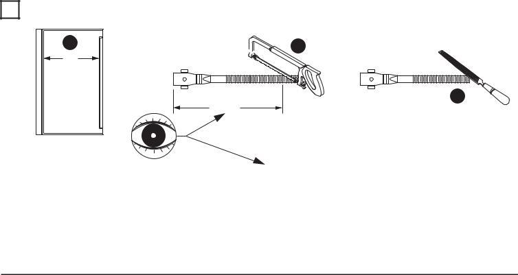
3Cut Connecting Rod
1 |
2 |
N |
|
Enclosure |
|
Working Depth |
|
(Flange to |
3 |
Mounting Plate) |
|
|
Rod Cut |
Connecting Rod |
Circuit Breaker |
Circuit Breaker |
Rod Cut |
|
Catalog Number |
Mechanism |
Frame |
||
|
||||
|
|
|
|
|
|
|
140G-G / 140MG-G |
N - 3-1/2" |
|
|
|
140G-I / 140MG-I |
||
|
1494V-M70 |
|
||
1494V-RA4 |
140G-H / 140MG-H |
N - 4" |
||
|
||||
|
140G-J / 140MG-J |
|||
|
|
|
||
|
1494V-M71 |
140G-K / 140MG-K |
N - 4-1/2" |
|
|
|
|
|
|
1494V-RB4 |
1494V-M72 |
140G-M / 140MG-M |
N - 3-3/4” |
|
140G-N / 140MG-N |
||||
|
|
|
||
|
|
|
|
Publication 1494V-IN105E-EN-P - September 2014 |
PN-242292 DIR 10000787413 (Version 04) |

4Variable Depth, Flange Operated Circuit Breaker Mechanisms
Circuit Breaker Installation
4a 140G-G; 140MG-G; 140G-I; 140MG-I
1 Verify that the disconnect handle and toggle on |
3 Install circuit breaker operating |
the circuit breaker are in the “OFF” position. |
mechanism into panel. |
2Rotate connecting rod into drive bar
(10) full turns of engagement.
|
140G-I |
|
140G-J |
|
140G-G |
|
140G-H |
R |
140G-G |
140G-I |
|
|
140G-H |
|
140G-J |
|
23 - 37 lb-in |
4Choose proper insulation barrier as labeled. Bend side panels of insulation barrier inward.
5
6
7
Remove liner from two-sided tape.
Align holes on insulation barrier with holes on operating mechanism. |
9 Attach toggle adjustment plate. |
|
|
Press firmly in place. |
|
TAPE
 L
L


 L
L
23 - 37 lb-in
8 Install circuit breaker onto insulation barrier and mechanism.
10 lb-in
Go to Page 11 to assemble connecting rod and springs to handle
Publication 1494V-IN105E-EN-P - September 2014 |
PN-242292 DIR 10000787413 (Version 04) |
Variable Depth, Flange Operated Circuit Breaker Mechanisms |
5 |
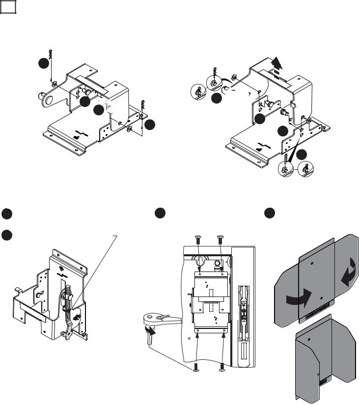
Circuit Breaker Installation (Cont'd)
4b 140G-H; 140MG-H; 140G-J; 140MG-J
Reposition bail mechanism
Removal
1
 2
2 


 4
4 

L |
3 |
L |
Installation
8 


7 |
L |
|
|
5 |
L |
6
9 Verify that the disconnect handle and toggle on |
11 Install circuit breaker operating |
the circuit breaker are in the “OFF” position. |
mechanism into panel. |
10 Rotate connecting rod into drive bar
(10) full turns of engagement.
|
|
140G-I |
|
|
140G-J |
|
|
140G-G |
|
|
140G-H |
|
|
140G-G |
|
R |
140G-I |
R |
140G-H |
|
140G-J |
||
|
|
23 - 37 lb-in |
12 Choose proper insulation barrier as labeled. Bend side panels of insulation barrier inward.
Publication 1494V-IN105E-EN-P - September 2014 |
PN-242292 DIR 10000787413 (Version 04) |
 Loading...