


 Loading...
User Guide
XM Electronic Overspeed Detection System
Catalog Numbers XM-442, XM-220, 1606-XLP

Important User Information
Solid-state equipment has operational characteristics differing from those of electromechanical equipment. Safety Guidelines for the Application, Installation and Maintenance of Solid State Controls (publication SGI-1.1 available from your local Rockwell Automation sales office or online at http://www.rockwellautomation.com/literature/) describes some important differences between solid-state equipment and hard-wired electromechanical devices. Because of this difference, and also because of the wide variety of uses for solid-state equipment, all persons responsible for applying this equipment must satisfy themselves that each intended application of this equipment is acceptable.
In no event will Rockwell Automation, Inc. be responsible or liable for indirect or consequential damages resulting from the use or application of this equipment.
The examples and diagrams in this manual are included solely for illustrative purposes. Because of the many variables and requirements associated with any particular installation, Rockwell Automation, Inc. cannot assume responsibility or liability for actual use based on the examples and diagrams.
No patent liability is assumed by Rockwell Automation, Inc. with respect to use of information, circuits, equipment, or software described in this manual.
Reproduction of the contents of this manual, in whole or in part, without written permission of Rockwell Automation, Inc., is prohibited.
Throughout this manual, when necessary, we use notes to make you aware of safety considerations.
WARNING: Identifies information about practices or circumstances that can cause an explosion in a hazardous environment, which may lead to personal injury or death, property damage, or economic loss.
ATTENTION: Identifies information about practices or circumstances that can lead to personal injury or death, property damage, or economic loss. Attentions help you identify a hazard, avoid a hazard, and recognize the consequence
SHOCK HAZARD: Labels may be on or inside the equipment, for example, a drive or motor, to alert people that dangerous voltage may be present.
BURN HAZARD: Labels may be on or inside the equipment, for example, a drive or motor, to alert people that surfaces may reach dangerous temperatures.
IMPORTANT Identifies information that is critical for successful application and understanding of the product.
Allen-Bradley, Rockwell Automation, and TechConnect are trademarks of Rockwell Automation, Inc.
DeviceNet is a trademark of the Open DeviceNet Vendor Association (ODVA).
Microsoft and Windows are registered trademarks of the Microsoft Corporation.
Trademarks not belonging to Rockwell Automation are property of their respective companies.

European Communities (EC) Directive Compliance
If this product has the CE mark it is approved for installation within the European Union and EEA regions. It has been designed and tested to meet the following directives.
EMC Directive
This product is tested to meet the Council Directive 89/336/EC Electromagnetic Compatibility (EMC) by applying the following standards, in whole or in part, documented in a technical construction file:
·EN 61000-6-4 EMC — Generic Standards, Part 6-4 — Emission Standard for Industrial Environments (Class A)
·EN 61000-6-2 EMC — Generic Standards, Part 6-2 — Immunity Standard for Industrial Environment
·EN 61326-6-2 Electromagnetic Equipment for Measurement, Control, and Laboratory Use — Industrial EMC Requirements
This product is intended for use in an industrial environment.
Low Voltage Directive
This product is tested to meet Council Directive 73/23/EEC Low Voltage by applying the safety requirements of EN 61131-2 Programmable Controllers, Part 2 — Equipment Requirements and Tests.
ATEX Directive
This product is certified to meet Council Directive 94/9/EC Equipment and Protective systems intended for use in Potentially Explosive Atmospheres by applying standard EN 60079-15 - Electrical apparatus for potentially explosive atmospheres, Part 15 - Type of protection "n", in whole or in part, documented in a technical construction file.
Rockwell Automation Publication GMSI10-UM015B-EN-E - June 2011 |
3 |

4 |
Rockwell Automation Publication GMSI10-UM015B-EN-E - June 2011 |

Table of Contents
Introduction
Installing the XM Electronic
Overspeed Detection System
Chapter 1
Introducing the Electronic Overspeed Detection System . . . . . . . . . . . 7 XM Module Components . . . . . . . . . . . . . . . . . . . . . . . . . . . . . . . . . . . . 9 XM-220 Module Components . . . . . . . . . . . . . . . . . . . . . . . . . . . . . 9 XM-442 Module Components . . . . . . . . . . . . . . . . . . . . . . . . . . . . 10 Using this Manual. . . . . . . . . . . . . . . . . . . . . . . . . . . . . . . . . . . . . . . . . . 10 Organization. . . . . . . . . . . . . . . . . . . . . . . . . . . . . . . . . . . . . . . . . . . 10 Document Conventions . . . . . . . . . . . . . . . . . . . . . . . . . . . . . . . . . 11
Chapter 2
XM Installation Requirements. . . . . . . . . . . . . . . . . . . . . . . . . . . . . . . . 14 Wiring Requirements . . . . . . . . . . . . . . . . . . . . . . . . . . . . . . . . . . . . 14 Power Requirements . . . . . . . . . . . . . . . . . . . . . . . . . . . . . . . . . . . . 14 Grounding Requirements . . . . . . . . . . . . . . . . . . . . . . . . . . . . . . . . 15 Mounting the Power Supply Modules. . . . . . . . . . . . . . . . . . . . . . . . . . 19 Mounting the Terminal Base Units . . . . . . . . . . . . . . . . . . . . . . . . . . . . 20 DIN Rail Mounting . . . . . . . . . . . . . . . . . . . . . . . . . . . . . . . . . . . . . 20 Interconnecting Terminal Base Units . . . . . . . . . . . . . . . . . . . . . . . 22 Panel/Wall Mounting . . . . . . . . . . . . . . . . . . . . . . . . . . . . . . . . . . . 22 Connecting Wiring for Your XM EODS . . . . . . . . . . . . . . . . . . . . . . . 24 Terminal Block Assignments. . . . . . . . . . . . . . . . . . . . . . . . . . . . . . 24 Typical XM EODS Wiring Diagram . . . . . . . . . . . . . . . . . . . . . . . 29 Connecting the Power Supply Modules . . . . . . . . . . . . . . . . . . . . . 29 Connecting the Overspeed/Circuit Fault Signals. . . . . . . . . . . . . . 32 Connecting the Relays . . . . . . . . . . . . . . . . . . . . . . . . . . . . . . . . . . . 32 Connecting the Remote Relay Reset Signal . . . . . . . . . . . . . . . . . . 36 Connecting the Transducers . . . . . . . . . . . . . . . . . . . . . . . . . . . . . . 37 Other XM-220 Connections . . . . . . . . . . . . . . . . . . . . . . . . . . . . . . 39 Mounting the XM Modules . . . . . . . . . . . . . . . . . . . . . . . . . . . . . . . . . . 39 LED Indicators . . . . . . . . . . . . . . . . . . . . . . . . . . . . . . . . . . . . . . . . . . . 41 LED Indicators for the XM-442 Module. . . . . . . . . . . . . . . . . . . . 41 LED Indicators for the XM-220 Module. . . . . . . . . . . . . . . . . . . . 42 Basic Operations . . . . . . . . . . . . . . . . . . . . . . . . . . . . . . . . . . . . . . . . . . 44 Powering Up the Modules. . . . . . . . . . . . . . . . . . . . . . . . . . . . . . . . 44 Manually Resetting the XM EODS Relays. . . . . . . . . . . . . . . . . . . 45
Publication GMSI10-UM015B-EN-E - June 2011

6 Table of Contents |
|
|
|
Chapter 3 |
|
Configuring the XM EODS |
Configuration Overview . . . . . . . . . . . . . . . . . . . . . . . . . . . . . . . . . . . . |
47 |
|
Using the XM Serial Configuration Utility . . . . . . . . . . . . . . . . . . . . . . |
49 |
|
Tachometer Parameters. . . . . . . . . . . . . . . . . . . . . . . . . . . . . . . . . . |
50 |
|
Alarm Parameters. . . . . . . . . . . . . . . . . . . . . . . . . . . . . . . . . . . . . . . |
52 |
|
Relay Parameters . . . . . . . . . . . . . . . . . . . . . . . . . . . . . . . . . . . . . . . |
53 |
|
4-20mA Output Parameters . . . . . . . . . . . . . . . . . . . . . . . . . . . . . . |
54 |
|
View Data from the XM-220 . . . . . . . . . . . . . . . . . . . . . . . . . . . . . |
56 |
|
Saving the Configuration to a File . . . . . . . . . . . . . . . . . . . . . . . . . |
56 |
|
Appendix A |
|
Specifications |
. . . . . . . . . . . . . . . . . . . . . . . . . . . . . . . . . . . . . . . . . . . . . . . . . . . . . . . . . |
59 |
Glossary |
. . . . . . . . . . . . . . . . . . . . . . . . . . . . . . . . . . . . . . . . . . . . . . . . . . . . . . . . . |
63 |
Index |
. . . . . . . . . . . . . . . . . . . . . . . . . . . . . . . . . . . . . . . . . . . . . . . . . . . . . . . . . |
67 |
Publication GMSI10-UM015B-EN-E - June 2011
Chapter 1
Introduction
This chapter provides an overview of the XM Electronic Overspeed Detection System. It also discusses the components of the Electronic Overspeed Detection System.
For information about |
See page |
|
|
Introducing the Electronic Overspeed Detection System |
7 |
|
|
XM Module Components |
9 |
|
|
Using this Manual |
10 |
|
|
Introducing the Electronic
Overspeed Detection
System
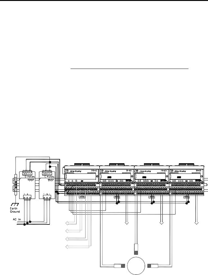
The XM® Electronic Overspeed Detection System (EODS) is a highly reliable, redundant system that fully meets the performance, measurement, and relay requirements of the American Petroleum Institute Standards 670 and 612 as pertaining to overspeed protection. It is intended for use on gas and steam turbine driven machinery where protection is required to prevent potentially catastrophic failures of the machine from overspeed events.
Figure 1.1 XM EODS
|
|
|
|
1440-REX03-04RG |
|
|
|
|
1440-SPD02-01RB |
|
|
|
|
1440-SPD02-01RB |
|
|
|
|
1440-SPD02-01RB |
||||
|
|
VOTED EODS RELAY |
|
|
|
|
DUAL SPEED |
|
|
|
|
DUAL SPEED |
|
|
|
|
DUAL SPEED |
|
|
||||
|
|
|
|
|
|
|
|
|
|
|
|
|
|
|
|
|
|
|
|
|
|
|
|
|
|
|
|
|
|
|
|
|
|
|
|
|
|
|
|
|
|
|
|
|
|
|
|
EODS Events |
|
|
|
(3) |
|
|
|
Shutdown |
|
|
|
Relay #1 |
Circuit |
Circuit |
Circuit |
|
|||
|
Fault |
Fault |
Fault |
Shutdown |
Relay |
Relay |
Relay |
Relay #2 |
|
|
|
Shutdown |
|
|
|
Relay #3 |
|
|
|
Alarm |
|
Transducer |
|
Relay |
|
|
|
|
Transducer |
Transducer |
|
Publication GMSI10-UM015B-EN-E - June 2011

8 Introduction
The XM EODS is comprised of the following components:
•Two Allen-Bradley™ 1606-XLP30E Power Supplies - The two power supply modules (85 - 264 VAC input, +24V DC output) provide redundant power to the EODS. Each power supply is independently capable of supplying power for the entire system. If one of the power supply modules fails, the system will continue to operate properly.
•Three XM-220 Dual Speed modules - The three XM-220 modules individually accept input signals from a proximity probe transducer or magnetic pickup. Each module measures the speed of the transducer and compares it against a user-defined danger threshold value. The modules also record the highest measured speed.
The XM-220 modules include an overspeed/circuit fault output signal, which is wired to the XM-442 module, as shown in Figure 1.1. If the XM-220 senses an overspeed condition or detects a failed speed sensor or logic device, it will activate its overspeed/circuit fault output signal.
Channel 1 of each of the XM-220 modules serves as the overspeed channel of the electronic overspeed detection system. The on-board relay in each of the XM-220 modules serves as the circuit fault relay for that overspeed channel. The XM-220 modules also include two 4-20mA outputs and a buffered output for each input channel.
For more information about the XM-220, refer to the XM-220 Dual Speed Module User Guide.
•XM-442 EODS Relay module - The XM-442 module provides the two-out-of-three or one-out-of-three voting logic. The module includes four high power relays that serve as the EODS alarm and shutdown relays.
The XM-442 module accepts the overspeed/circuit fault outputs from the three XM-220 modules. If at least two of the three overspeed/circuit fault outputs are active, the XM-442 module activates the three shutdown relays. If at least one of the three overspeed/circuit fault outputs is active, or there is failure of a logic device in the XM-442 or a failure of a power supply, the XM-442 activates the alarm relay. Note that the shutdown relays are not affected by a single power supply failure or a circuit fault within the XM-442 module. The XM-442 contains redundant logic which allows it to operate correctly even in the presence of a single internal circuit fault.
The EODS modules include LED indicators for indicating power failures, alarm and shutdown status, and circuit faults. The XM-442 module has no configurable parameters. The XM-220 module can be configured remotely via the DeviceNet network, or locally using a serial connection to a PC or laptop.
Publication GMSI10-UM015B-EN-E - June 2011

Introduction |
9 |
|
|
|
The XM EODS can operate stand-alone, or it can be deployed on a standard |
|
or dedicated DeviceNet network where it can provide real-time data and |
|
system information to other XM modules, Programmable Logic Controllers |
|
(PLCs), distributed control systems (DCS), and Condition Monitoring |
|
Systems. |
XM Module Components |
The XM modules in the XM EODS consist of a terminal base and an |
|
instrument module. The instrument module and terminal base for the XM-220 |
|
and XM-442 is shown below. |
|
For more information about the Allen-Bradley 1606-XLP30E Power Supply |
|
modules, refer to the 1606-XLP Power Supply Installation and Operation |
|
manual. |
|
XM-220 Module Components |
|
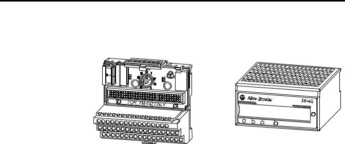
Figure 1.2 XM-220 Module Components |
DUAL SPEED |
1440-SPD02-01RB |
XM-941 Speed/Position Module |
XM-220 Dual Speed Module |
Terminal Base Unit |
Cat. No. 1440-SPD02-01RB |
Cat. No. 1440-TB-B |
|
•XM-941 Position/Speed Module Terminal Base - A DIN rail mounted base unit that provides terminations for all field wiring required by Position and Speed modules, including the XM-220.
•XM-220 Dual Speed Module - Mounts on the XM-941 terminal base unit via a keyswitch and a 96-pin connector. The XM-220 contains the measurement electronics, processor, relay, and serial interface port for local configuration.
Publication GMSI10-UM015B-EN-E - June 2011
10 Introduction
XM-442 Module Components
Figure 1.3 XM-442 Module Components
VOTED |
EODS RELAY |
1440- |
|
REX03-04RG |
XM-946 EODS Relay Terminal Base Unit |
XM-442 |
Voted EODS Relay Module |
Cat. No. 1440-TB-G |
Cat. |
No. 1440-REX03-04RG |
Using this Manual
•XM-946 EODS Relay Terminal Base Unit - A DIN rail mounted base unit that provides terminations for all field wiring required by the XM-442.
•XM-442 Voted EODS Relay Module - Mounts on the XM-946 terminal base unit via a keyswitch and a 96-pin connector. The XM-442 contains four on-board relays. The XM-442 has no configurable parameters.
This manual explains the installation and provides the configuration procedures for the XM Electronic Overspeed Detection System. It is intended for anyone who installs or uses the XM EODS.
This manual does not contain instructions for installing the Allen-Bradley 1606-XLP30E Power Supply modules. Refer to 1606-XLP Power Supply Installation and Operation manual.
In addition, it only provides installation instructions for the XM-220 as it pertains to the EODS. Refer to the XM-220 Dual Speed Module User Guide for more information about the XM-220 module.
Organization
To help you navigate through this manual, it is organized in chapters based on these tasks and topics.
Chapter 1 "Introduction" contains an overview of the XM Electronic Overspeed Detection System and information about this manual.
Publication GMSI10-UM015B-EN-E - June 2011
Introduction 11
Chapter 2 "Installing the XM Electronic Overspeed Detection System" describes how to install, wire, and operate the XM EODS.
Chapter 3 "Configuring the XM EODS" provides information to help you configure your XM Electronic Overspeed Detection System using the XM Serial Configuration Utility software.
Appendix A "Specification" lists the technical specifications for the XM-442 Voted EODS Relay module.
For definitions of terms used in this Guide, see the Glossary at the end of the Guide.
Document Conventions
There are several document conventions used in this manual, including the following:
The XM Electronic Overspeed Detection System is also referred to as XM EODS and electronic overspeed detection system throughout this manual.
|
A tip indicates additional information which may be |
|
TIP |
||
helpful. |
||
|
||
|
|
This convention presents an example. |
|
EXAMPLE |
||
|
||
|
|
|
|
|
Publication GMSI10-UM015B-EN-E - June 2011

12 Introduction
Publication GMSI10-UM015B-EN-E - June 2011

Chapter 2
Installing the XM Electronic Overspeed
Detection System
This chapter discusses how to install and wire the XM Electronic Overspeed Detection System. It also describes the LED indicators and the basic operation of the XM EODS.
For information about |
See page |
|
|
|
|
XM Installation Requirements |
14 |
|
|
|
|
Mounting the Power Supply Modules |
19 |
|
|
|
|
Mounting the Terminal Base Units |
20 |
|
|
|
|
Connecting Wiring for Your XM EODS |
24 |
|
|
|
|
Mounting the XM Modules |
39 |
|
|
|
|
LED Indicators |
41 |
|
|
|
|
Basic Operations |
44 |
|
|
|
|
|
|
|
|
|
|
Environment and Enclosure |
|
ATTENTION |
||||
|
||||
|
|
|
This equipment is intended for use in a Pollution Degree 2 |
|
|
|
|
||
|
|
|
Industrial environment, in overvoltage Category II applications |
|
|
|
|
(as defined in IED publication 60664–1), at altitudes up to 2000 |
|
|
|
|
||
|
|
|
meters without derating. |
|
|
|
|
This equipment is supplied as “open type” equipment. It must be |
|
|
|
|
mounted within an enclosure that is suitably designed for those |
|
|
|
|
specific environmental conditions that will be present, and |
|
|
|
|
appropriately designed to prevent personal injury resulting from |
|
|
|
|
accessibility to live parts. The interior of the enclosure must be |
|
|
|
|
accessible only by the use of a tool. Subsequent sections of this |
|
|
|
|
publication may contain additional information regarding specific |
|
|
|
|
enclosure type ratings that are required to comply with certain |
|
|
|
|
product safety certifications. |
|
See NEMA Standards publication 250 and IEC publication 60529, as applicable, for explanations of the degrees of protection provided by different types of enclosures.
Publication GMSI10-UM015B-EN-E - June 2011
14 Installing the XM Electronic Overspeed Detection System
XM Installation
Requirements
This section describes wire, power, and grounding requirements for an XM system.
Wiring Requirements
Use solid or stranded wire. All wiring should meet the following specifications:
•12 to 28 AWG copper conductors without pretreatment; 8 AWG required for grounding the DIN rail for electromagnetic interference (emi) purposes
•Recommended strip length 8 millimeters (0.31 inches)
•Minimum insulation rating of 300V
•Soldering the conductor is forbidden
•Wire ferrules can be used with stranded conductors; copper ferrules recommended
|
|
|
See the XM Documentation and Configuration Utility CD |
|
ATTENTION |
||||
for Hazardous Locations installation drawings. The XM |
||||
|
|
|
||
|
|
|
||
|
|
|
Documentation and Configuration Utility CD is packaged |
|
|
|
|
with the XM modules. |
|
|
|
|
|
|
|
|
|
|
|
Power Requirements
Before installing your module, calculate the power requirements of all modules in each chassis. The total current draw through the side connector cannot exceed 3A. Refer to the specifications for the specific modules for power requirements.
|
|
|
A separate power connection is necessary if the total |
|
ATTENTION |
||||
current draw of the interconnecting modules is greater than |
||||
|
|
|
||
|
|
|
||
|
|
|
3A. |
|
|
|
|
|
|
|
|
|
|
|
|
|
|
|
|
Publication GMSI10-UM015B-EN-E - June 2011

Installing the XM Electronic Overspeed Detection System |
15 |
|
|
Figure 2.1 is an illustration of wiring modules using separate power connections.
Figure 2.1 XM Modules with Separate Power Connections
1440-VST02-01RA |
1440-REX00-04RD |
1440-VST02-01RA |
1440-REX00-04RD |
DYNAMIC MEASUREMENT |
EXPANSION RELAY |
DYNAMIC MEASUREMENT |
EXPANSION RELAY |
Power
Supply
|
1440-RMA00-04RC |
1440-REX00-04RD |
1440-TSP02-01RB |
1440-REX00-04RD |
MASTER RELAY |
EXPANSION RELAY |
POSITION |
|
EXPANSION RELAY |
Grounding Requirements
Use these grounding requirements to ensure safe electrical operating circumstances, and to help avoid potential emi and ground noise that can cause unfavorable operating conditions for your XM system.
DIN Rail Grounding
The XM modules make a chassis ground connection through the DIN rail. The DIN rail must be connected to a ground bus or grounding electrode conductor using 8 AWG or 1 inch copper braid. See Figure 2.2 on page 16.
Use zinc-plated, yellow-chromated steel DIN rail (Allen-Bradley part no. 199-DR1 or 199-DR4) or equivalent to assure proper grounding. Using other DIN rail materials (e.g. aluminum, plastic, etc.), which can corrode, oxidize, or are poor conductors can result in improper or intermittent platform grounding.
Publication GMSI10-UM015B-EN-E - June 2011

16 Installing the XM Electronic Overspeed Detection System
Figure 2.2 XM System DIN Rail Grounding
1
Power
Supply
1440-VST02-01RA |
1440-REX00-04RD |
1440-VST02-01RA |
1440-REX00-04RD |
DYNAMIC MEASUREMENT |
EXPANSION RELAY |
DYNAMIC MEASUREMENT |
EXPANSION RELAY |
|
1440-RMA00-04RC |
1440-REX00-04RD |
1440-TSP02-01RB |
1440-REX00-04RD |
MASTER RELAY |
EXPANSION RELAY |
POSITION |
|
EXPANSION RELAY |
1
Power
Supply
1440-VST02-01RA |
1440-REX00-04RD |
1440-VST02-01RA |
1440-REX00-04RD |
DYNAMIC MEASUREMENT |
EXPANSION RELAY |
DYNAMIC MEASUREMENT |
EXPANSION RELAY |
1Use 14 AWG wire. If it is desired to isolate the power supply because of possible ground loops, do not connect 24V Common to earth as illustrated in Figure 2.2. When the 24V supply is isolated from earth, it is recommended to use an isolator on the RS-232 lines. Refer to the XM-220 Dual Speed Module User Guide.
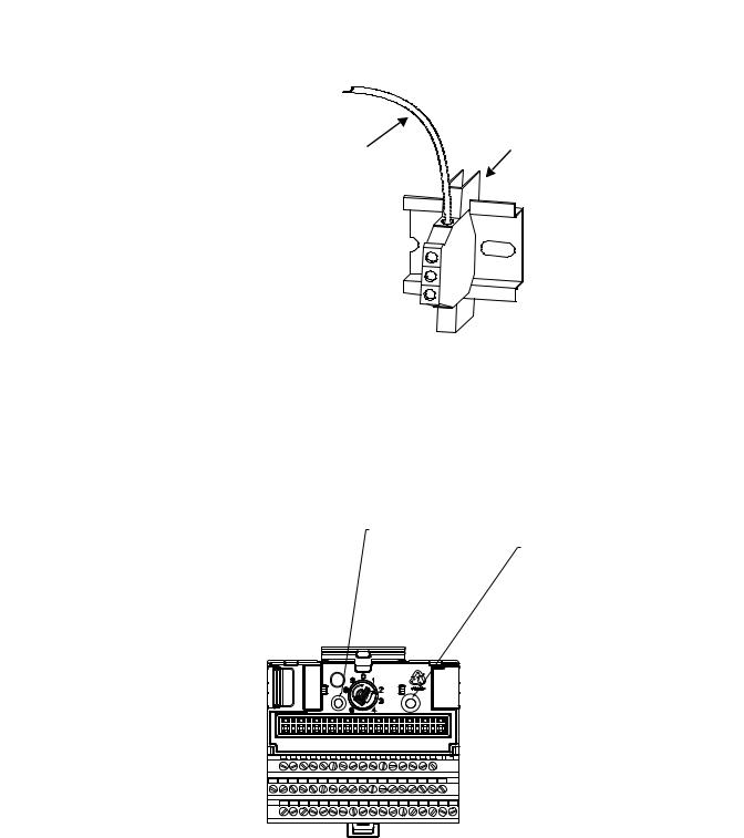
The grounding wire can be connected to the DIN rail using a DIN Rail Grounding Block (Figure 2.3).
Publication GMSI10-UM015B-EN-E - June 2011
Installing the XM Electronic Overspeed Detection System |
17 |
|
|
Figure 2.3 DIN Rail Grounding Block
To Earth Ground
AWG 8 Wire
Din Rail Grounding Block
Cat. No. 1492-WG10
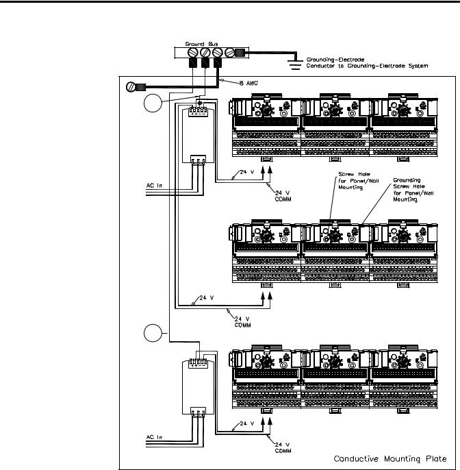
Panel/Wall Mount Grounding
The XM modules can also be mounted to a conductive mounting plate that is grounded. See Figure 2.5. Use the grounding screw hole provided on the terminal base to connect the mounting plate the Chassis terminals.
Figure 2.4 Grounding Screw on XM Terminal Base
Screw hole for
panel/wall mounting. Grounding screw hole for panel/ wall
mounting.
Publication GMSI10-UM015B-EN-E - June 2011
18 Installing the XM Electronic Overspeed Detection System
Figure 2.5 Panel/Wall Mount Grounding
1
Power
Supply
1 
Power
Supply
1Use 14 AWG wire. If it is desired to isolate the power supply because of possible ground loops, do not connect 24V Common to earth as illustrated in Figure 2.2. When the 24V supply is isolated from earth, it is recommended to use an isolator on the RS-232 lines. Refer to the XM-220 Dual Speed Module User Guide.
Publication GMSI10-UM015B-EN-E - June 2011

Installing the XM Electronic Overspeed Detection System |
19 |
|
|
24V Common Grounding
It is recommended that all 24V power to the XM modules is grounded. When two or more power supplies power the XM system, ground the 24V Commons at a single point, such as the ground bus bar.
For applications where redundant power supplies are used, only one power supply needs to be grounded. The XM module ties the two 24V Common lines together.
|
The 24V Common and Signal Common terminals are |
|
IMPORTANT |
||
internally connected. They are isolated from the Chassis |
||
|
||
|
||
|
terminals unless they are connected to ground as described |
|
|
in this section. See Terminal Block Assignments on page 24 |
|
|
for more information. |
|
|
|
Mounting the Power Supply
Modules
Transducer Grounding
Make certain the transducers are electrically isolated from earth ground. Cable shields must be grounded at one end of the cable, and the other end left floating or not connected. It is recommended that where possible, the cable shield be grounded at the XM terminal base by connecting to a Chassis terminal and not at the transducer.
Switch Input Grounding
The Switch Input circuits are electrically isolated from other circuits. It is recommended that the Switch RTN signal be grounded at a single point. Connect the Switch RTN signal to the XM terminal base (Chassis terminal) or directly to the DIN rail, or ground the signal at the switch or other equipment that is wired to the switch.
The XM EODS requires two Allen Bradley power supply modules (Cat. No. 1606-XLP30E). The power supply modules are DIN rail mountable and provide redundant power to the XM EODS. These modules provide all the system power and each can be powered by +24V dc and/or 85 to 264V ac. The outputs of the two power supply modules are connected to the terminal base units of the XM modules. See Figure 2.7 on page 29. A failure in one of the power supplies will not affect the operation of the EODS.
Refer to the documentation that was shipped with the 1606-XLP power supply for instructions on how to install the power supply modules.
Publication GMSI10-UM015B-EN-E - June 2011
20 Installing the XM Electronic Overspeed Detection System
Mounting the Terminal
Base Units
The XM family includes several different terminal base units to serve all of the measurement modules.
•The XM-941 terminal base, Cat. No. 1440-TB-B, is the only terminal base unit used with the XM-220 module.
•The XM-946 terminal base, Cat. No. 1440-TB-G, is the only terminal base unit used with the XM-442 module.
The terminal base can be DIN rail or wall/panel mounted. Refer to the specific method of mounting below.
|
|
|
The XM modules make a chassis ground connection |
|
ATTENTION |
||||
through the DIN rail. Use zinc plated, yellow chromated |
||||
|
|
|
||
|
|
|
||
|
|
|
steel DIN rail to assure proper grounding. Using other |
|
|
|
|
DIN rail materials (e.g. aluminum, plastic, etc.), which can |
|
|
|
|
corrode, oxidize or are poor conductors can result in |
|
|
|
|
improper or intermittent platform grounding. |
|
You can also mount the terminal base to a grounded mounting plate. Refer to Panel/Wall Mount Grounding on page 17.
DIN Rail Mounting
Use the steps below to mount the XM-941 and XM-946 terminal base units on a DIN rail. We recommend you mount the XM-946 terminal base first, next to the power supply modules (see Figure 2.7 on page 29).
Publication GMSI10-UM015B-EN-E - June 2011
Installing the XM Electronic Overspeed Detection System |
21 |
|
|
1.Position the XM-946 terminal base on the 35 x 7.5mm DIN rail (A) (A-B pt no. 199-DR1 or 199-DR4).
Position terminal base at a slight angle and hook over the top of the DIN rail.
2.Slide the terminal base unit over leaving room for the side connector (B).
3.Rotate the terminal base onto the DIN rail with the top of the rail hooked under the lip on the rear of the terminal base.
4.Press down on the terminal base unit to lock the terminal base on the DIN rail. If the terminal base does not lock into place, use a screwdriver or similar device to open the locking tab, press down on the terminal base until flush with the DIN rail and release the locking tab to lock the base in place.
Publication GMSI10-UM015B-EN-E - June 2011
22 Installing the XM Electronic Overspeed Detection System
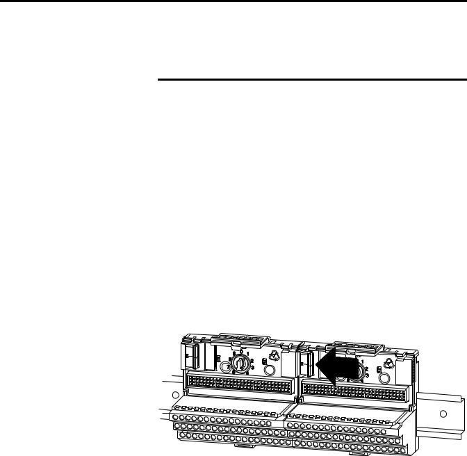
Interconnecting Terminal Base Units
Follow the steps below to install the XM-941 terminal base units.
|
Make certain you install the terminal base units in order of |
|
IMPORTANT |
||
left to right. |
||
|
||
|
||
|
|
1.Position the XM-941 terminal base on the 35 x 7.5mm DIN rail (A).
2.Make certain the side connector (B) is fully retracted into the base unit.
3.Slide the terminal base unit over tight against the neighboring terminal base. Make sure the hook on the terminal base slides under the edge of the terminal base unit.
4.Press down on the terminal base unit to lock the terminal base on the DIN rail. If the terminal base does not lock into place, use a screwdriver or similar device to open the locking tab, press down on the terminal base until flush with the DIN rail and release the locking tab to lock the base in place.
5.Gently push the side connector into the side of the neighboring terminal base unit to complete the backplane connection.
6. Repeat the steps to install the other two XM-941 terminal base units.
Panel/Wall Mounting
Installation on a wall or panel consists of:
•laying out the drilling points on the wall or panel
•drilling the pilot holes for the mounting screws
•installing the terminal base units and securing them to the wall or panel
Publication GMSI10-UM015B-EN-E - June 2011
Loading...