


 Loading...
Installation Instructions
ControlLogix DeviceNet Scanner Module
Catalog Numbers 1756-DNB, Series C and D
Topic |
Page |
|
|
|
|
|
|
Important User Information |
2 |
|
|
|
|
|
|
Preventing Electrostatic Discharge |
3 |
|
|
|
|
|
|
European Hazardous Location Approval - European Zone 2 Certification |
4 |
|
|
|
|
|
|
Environment and Enclosure |
5 |
|
|
|
|
|
|
North American Hazardous Location Approval |
6 |
|
|
|
|
|
|
About this Publication |
6 |
|
|
|
|
|
|
About the Module |
7 |
|
|
|
|
|
|
Before You Begin |
7 |
|
|
|
|
|
|
Determine Module Slot Location |
8 |
|
|
|
|
|
|
Change Module Settings |
9 |
|
|
|
|
|
|
Install the Module in the Chassis |
16 |
|
|
|
|
|
|
Configure the Scan List |
27 |
|
|
|
|
|
|
Monitor and Troubleshoot Devices in the Module Scan List |
27 |
|
|
|
|
|
|
Interpret the Status Indicators |
35 |
|
|
|
|
|
|
Understand ControlLogix Controller Interface Structures |
38 |
|
|
|
|
|
|
Specifications |
43 |
|
|
|
|
|
|
Additional Resources |
47 |
|
|
|
|
|
|
|
|
|
|
|
|
|
|
2 ControlLogix DeviceNet Scanner Module
Important User Information
Solid state equipment has operational characteristics differing from those of electromechanical equipment. Safety Guidelines for the Application, Installation and Maintenance of Solid State Controls Publication SGI-1.1 available from your local Rockwell Automation sales office or online at http://literature.rockwellautomation.com) describes some important differences between solid state equipment and hard-wired electromechanical devices. Because of this difference, and also because of the wide variety of uses for solid state equipment, all persons responsible for applying this equipment must satisfy themselves that each intended application of this equipment is acceptable.
In no event will Rockwell Automation, Inc. be responsible or liable for indirect or consequential damages resulting from the use or application of this equipment.
The examples and diagrams in this manual are included solely for illustrative purposes. Because of the many variables and requirements associated with any particular installation, Rockwell Automation, Inc. cannot assume responsibility or liability for actual use based on the examples and diagrams.
No patent liability is assumed by Rockwell Automation, Inc. with respect to use of information, circuits, equipment, or software described in this manual.
Reproduction of the contents of this manual, in whole or in part, without written permission of Rockwell Automation, Inc., is prohibited.
Throughout this manual, when necessary, we use notes to make you aware of safety considerations.
|
WARNING |
|
Identifies information about practices or circumstances that can cause an explosion in |
||||
|
|
|
|
|
|
|
|
|
|
|
|
|
|
|
a hazardous environment, which may lead to personal injury or death, property |
|
|
|
|
|
|
|
damage, or economic loss. |
|
|
|
|
|
|
|
|
|
|
|
|
|
|
|
|
|
|
|
|
|
|
|
Identifies information that is critical for successful application and understanding of |
|
IMPORTANT |
||||||
|
the product. |
||||||
|
|
|
|
|
|
|
|
|
|
|
|
|
|
||
|
|
|
|
|
|
|
|
|
ATTENTION |
|
Identifies information about practices or circumstances that can lead to personal |
||||
|
|
|
|
|
|
|
|
|
|
|
|
|
|
|
injury or death, property damage, or economic loss. Attentions help you identify a |
|
|
|
|
|
|
|
hazard, avoid a hazard and recognize the consequences. |
|
|
|
|
|
|
|
|
SHOCK HAZARD
Labels may be on or inside the equipment (for example,a drive or motor) to alert people that dangerous voltage may be present.
BURN HAZARD
Labels may be on or inside the equipment (for example, a drive or motor) to alert people that surfaces may reach dangerous temperatures.
Publication 1756-IN566D-EN-P - June 2008

|
|
|
ControlLogix DeviceNet Scanner Module 3 |
|
|
|
|
Preventing Electrostatic Discharge |
|||
|
|
|
|
|
|
|
This equipment is sensitive to electrostatic discharge, which can cause |
ATTENTION |
|||
|
|
|
internal damage and affect normal operation. Follow these guidelines when |
|
|
|
you handle this equipment: |
|
|
|
• Touch a grounded object to discharge potential static. |
|
|
|
|
•Wear an approved grounding wriststrap.
•Do not touch connectors or pins on component boards.
•Do not touch circuit components inside the equipment.
•Use a static-safe workstation, if available.
•Store the equipment in appropriate static-safe packaging when not in use.
Publication 1756-IN566D-EN-P - June 2008

4 ControlLogix DeviceNet Scanner Module
European Hazardous Location Approval - European Zone 2 Certification
The following applies when the product bears the EEx Marking).
This equipment is intended for use in potentially explosive atmospheres as defined by European Union Directive 94/9/EC.
The LCIE (Laboratoire Central des Industries Electriques) certifies that this equipment has been found to comply with the Essential Health and Safety Requirements relating to the design and construction of Category 3 equipment intended for use in potentially explosive atmospheres, given in Annex II to this Directive.
Compliance with the Essential Health and Safety Requirements has been assured by compliance with EN 60079-15.
IMPORTANT • This equipment is not resistant to sunlight or other sources of UV radiation.
•This equipment must be installed in an enclosure providing at least IP54 protection when applied in Class I, Zone 2 environments.
•This equipment shall be used within its specified ratings defined by Rockwell Automation.
•Provision shall be made to prevent the rated voltage from being exceeded by transient disturbances of more than 40% when applied in Class I, Zone 2 environments.
•This equipment must be used only with ATEX certified backplanes.
Publication 1756-IN566D-EN-P - June 2008

|
|
|
ControlLogix DeviceNet Scanner Module 5 |
|
|
|
|
Environment and Enclosure |
|||
|
|
|
|
|
|
|
This equipment is intended for use in a Pollution Degree 2 industrial |
ATTENTION |
|||
|
|
|
environment, in overvoltage Category II applications (as defined in IEC |
|
|
|
publication 60664-1), at altitudes up to 2000 m (6562 ft) without derating. |
|
|
|
This equipment is considered Group 1, Class A industrial equipment according |
|
|
|
|
|
|
|
to IEC/CISPR Publication 11. Without appropriate precautions, there may be |
|
|
|
potential difficulties ensuring electromagnetic compatibility in other |
|
|
|
environments due to conducted as well as radiated disturbance. |
|
|
|
This equipment is supplied as open-type equipment. It must be mounted within |
|
|
|
an enclosure that is suitably designed for those specific environmental |
|
|
|
conditions that will be present and appropriately designed to prevent personal |
|
|
|
injury resulting from accessibility to live parts. The enclosure must have |
|
|
|
suitable flame-retardant properties to prevent or minimize the spread of flame, |
|
|
|
complying with a flame spread rating of 5VA, V2, V1, V0 (or equivalent) if |
|
|
|
non-metallic. The interior of the enclosure must be accessible only by the use |
|
|
|
of a tool. Subsequent sections of this publication may contain additional |
|
|
|
information regarding specific enclosure type ratings that are required to |
|
|
|
comply with certain product safety certifications. |
|
|
|
Besides this publication, see: |
•Industrial Automation Wiring and Grounding Guidelines, for additional installation requirements, Allen-Bradley publication 1770-4.1.
•NEMA Standards publication 250 and IEC publication 60529, as applicable, for explanations of the degrees of protection provided by different types of enclosure.
Publication 1756-IN566D-EN-P - June 2008
6 ControlLogix DeviceNet Scanner Module
North American Hazardous Location Approval
The following information applies when |
|
Informations sur l’utilisation de cet |
|||||||||
operating this equipment in hazardous |
|
équipement en environnements dangereux. |
|||||||||
locations. |
|
|
|
|
|
|
|
|
|||
|
|
|
|||||||||
Products marked "CL I, DIV 2, GP A, B, C, D" are suitable for |
|
Les produits marqués "CL I, DIV 2, GP A, B, C, D" ne |
|||||||||
use in Class I Division 2 Groups A, B, C, D, Hazardous |
|
conviennent qu'à une utilisation en environnements de |
|||||||||
Locations and nonhazardous locations only. Each product is |
|
Classe I Division 2 Groupes A, B, C, D dangereux et non |
|||||||||
supplied with markings on the rating nameplate indicating |
|
dangereux. Chaque produit est livré avec des marquages sur |
|||||||||
the hazardous location temperature code. When |
|
sa plaque d'identification qui indiquent le code de |
|||||||||
combining products within a system, the most adverse |
|
température pour les environnements dangereux. Lorsque |
|||||||||
temperature code (lowest "T" number) may be used to help |
|
plusieurs produits sont combinés dans un système, le code de |
|||||||||
determine the overall temperature code of the system. |
|
température le plus défavorable (code de température le plus |
|||||||||
Combinations of equipment in your system are subject to |
|
faible) peut être utilisé pour déterminer le code de |
|||||||||
investigation by the local Authority Having Jurisdiction at |
|
température global du système. Les combinaisons |
|||||||||
the time of installation. |
|
d'équipements dans le système sont sujettes à inspection par |
|||||||||
|
|
|
|
|
|
|
les autorités locales qualifiées au moment de l'installation. |
||||
|
|
|
|
|
|
|
|
|
|
|
|
|
|
|
|
|
EXPLOSION HAZARD - |
|
|
|
|
|
RISQUE D’EXPLOSION – |
|
WARNING |
AVERTISSEMENT |
|||||||||
|
|
|
|
|
• Do not disconnect equipment unless |
|
|
|
|
|
• Couper le courant ou s'assurer |
|
|
|
|
|
power has been removed or the |
|
|
|
|
|
que l'environnement est classé |
|
|
|
|
|
area is known to be nonhazardous. |
|
|
|
|
|
non dangereux avant de |
|
|
|
|
|
• Do not disconnect connections to |
|
|
|
|
|
débrancher l'équipement. |
|
|
|
|
|
this equipment unless power has |
|
|
|
|
|
• Couper le courant ou s'assurer |
|
|
|
|
|
been removed or the area is known |
|
|
|
|
|
que l'environnement est classé |
|
|
|
|
|
to be nonhazardous. Secure any |
|
|
|
|
|
non dangereux avant de |
|
|
|
|
|
external connections that mate to |
|
|
|
|
|
débrancher les connecteurs. Fixer |
|
|
|
|
|
this equipment by using screws, |
|
|
|
|
|
tous les connecteurs externes |
|
|
|
|
|
sliding latches, threaded |
|
|
|
|
|
reliés à cet équipement à l'aide |
|
|
|
|
|
connectors, or other means |
|
|
|
|
|
de vis, loquets coulissants, |
|
|
|
|
|
provided with this product. |
|
|
|
|
|
connecteurs filetés ou autres |
|
|
|
|
|
• Substitution of components may |
|
|
|
|
|
moyens fournis avec ce produit. |
|
|
|
|
|
impair suitability for Class I, |
|
|
|
|
|
• La substitution de composants |
|
|
|
|
|
Division 2. |
|
|
|
|
|
peut rendre cet équipement |
|
|
|
|
|
• If this product contains batteries, |
|
|
|
|
|
inadapté à une utilisation en |
|
|
|
|
|
they must only be changed in an |
|
|
|
|
|
environnement de Classe I, |
|
|
|
|
|
area known to be nonhazardous. |
|
|
|
|
|
Division 2. |
|
|
|
|
|
|
|
|
|
|
|
• S'assurer que l'environnement est |
|
|
|
|
|
|
|
|
|
|
|
classé non dangereux avant de |
|
|
|
|
|
|
|
|
|
|
|
changer les piles. |
|
|
|
|
|
|
|
|
|
|
|
|
About this Publication
Use this publication as a guide to install the module. This publication describes hardware installation only. For configuration information, refer to the DeviceNet Modules in Logix5000 Systems User Manual, publication DNET-UM004.
Publication 1756-IN566D-EN-P - June 2008

ControlLogix DeviceNet Scanner Module 7
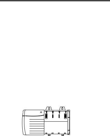
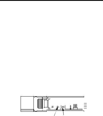
About the Module
Use this figure to identify the external features of the module.
Top View
Front View
Backplane
Connector
Front
Panel
USB Port
DeviceNet
Port
Side View
31713-M
Before You Begin
Before you install the module, you must install and connect a ControlLogix chassis and power supply.
Power |
1756-A4 |
|
Chassis |
||
Supply |
||
|
||
|
20805-M |
Publication 1756-IN566D-EN-P - June 2008
8 ControlLogix DeviceNet Scanner Module
To install these products, refer to these publications.
Publication References
Chassis Type |
Chassis |
Power Supply |
Power Supply |
|
|
Installation |
|
Installation |
|
|
Instructions |
|
Instructions |
|
|
|
|
|
|
Series B: |
Pub. No. |
1756-PA72/B |
Pub. No. |
|
1756-A4, 1756-A7, |
1756-IN080 |
|
1756-IN078 |
|
1756-PB72/B |
||||
1756-A10, 1756-A13 |
|
|
||
|
|
|
||
|
|
1756-PA75/A |
Pub. No. |
|
|
|
|
1756-IN596 |
|
|
|
1756-PB75/A |
||
|
|
|
||
|
|
|
|
Determine Module Slot Location
Install the module in any slot in the ControlLogix chassis. You can install multiple 1756-DNB scanner modules in the same chassis.
The following figure shows chassis slot numbering in a 4-slot chassis. Slot 0 is the first slot and is always the leftmost slot in the chassis.
Slot 0 |
Slot 2 |
||||||||||
|
|
Slot 1 |
|
|
Slot 3 |
||||||
|
|
|
|
||||||||
|
|
|
|
|
|
|
|
|
|
|
|
|
|
|
|
|
|
|
|
|
|
|
|
|
|
|
|
|
|
|
|
|
|
|
|
|
|
|
|
|
|
|
|
|
|
|
|
|
|
|
|
|
|
|
|
|
|
|
|
|
|
|
|
|
|
|
|
|
|
|
|
Power Supply |
Chassis |
20806
Publication 1756-IN566D-EN-P - June 2008
ControlLogix DeviceNet Scanner Module 9
Change Module Settings
The module ships with these settings.
Factory Setting Values
Factory Settings |
|
Value |
|
|||||||||||||||||||
|
|
|
|
|
|
|
|
|
|
|
|
|
|
|
|
|
|
|
|
|
|
|
Rotary switches |
|
999 |
|
|
|
|
|
|
|
|
|
|
|
|
|
|
|
|
||||
|
|
|
|
|
|
|
|
|
|
|
|
|
|
|
|
|
|
|
|
|
|
|
Communication (data) rate |
|
Software settable (default 125 Kbps) |
|
|||||||||||||||||||
|
|
|
|
|
|
|
|
|
|
|
|
|
|
|
|
|
|
|
|
|
|
|
Node address |
|
Software settable (default 63) |
|
|||||||||||||||||||
|
|
|
|
|
|
|
|
|
|
|
|
|
|
|
|
|
|
|
|
|
|
|
|
|
|
|
|
|
|
|
|
|
|
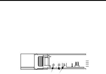
Top of Module |
|
|
|
||||||||
|
|
|
|
|
|
|
|
|
|
|
|
|
|
|||||||||
|
|
|
|
|
|
|
|
|
|
|
|
|
|
|||||||||
Front of Module |
|
|
|
|
||||||||||||||||||
|
|
|
|
|||||||||||||||||||
|
|
|
|
|
|
|
|
|
|
|
|
|
|
|
|
|
|
|
||||
|
|
|
|
|
|
|
|
|
|
|
|
|
|
|
|
|
|
|
|
|
|
|
|
|
|
|
|
|
|
|
|
|
|
|
|
|
|
|
|
|
|
|
|||
Communication (Data) |
|
|
|
|
|
31587 |
||||||||||||||||
|
|
|
|
|
|
|||||||||||||||||
|
|
|
|
DeviceNet Node Address Rotary |
||||||||||||||||||
Rate Rotary Switch |
|
|
|
|
Switches |
|
||||||||||||||||
Publication 1756-IN566D-EN-P - June 2008
10 ControlLogix DeviceNet Scanner Module
Set the Communication Rate
The 1756-DNB scanner module supports the following DeviceNet network communication rates:
•125 Kbps
•250 Kbps
•500 Kbps
The factory default setting is 125 Kbps.
ATTENTION |
Do not change the communication rate on an active network. Unpredictable |
||
|
|
|
operation may result. In addition, the new communication rate does not take |
|
|
|
effect until you cycle power to the 1756-DNB scanner module. |
|
|
|
|
Change the communication rate by setting the rotary switch or commissioning the 1756-DNB scanner module in RSNetWorx for DeviceNet software.
Use the switch to select a specific communication rate. When the switch is set to 3...9 (except for 888), you can configure the communication rate with RSNetWorx for DeviceNet software. When all three switches are set to 8, the 1756-DNB scanner module will reset to factory default settings at powerup.
See Restore the Factory Default Settings on page 15 for more information. See the following table for switch settings.
Publication 1756-IN566D-EN-P - June 2008
ControlLogix DeviceNet Scanner Module 11
Communication Rate Rotary Switch
Top of Module
Front of Module
31587
Communication (Data) Rate Rotary Switch
Switch Settings and Communication Rate
Switch Setting |
Communication Rate |
0125 Kbps
1250 Kbps
2500 Kbps
8When all three switches are set to 8, this resets the 1756-DNB scanner module to factory default settings. Do not use for normal operation.
All other values |
Select the communication rate with RSNetWorx for |
|
DeviceNet software. |
Publication 1756-IN566D-EN-P - June 2008

12 ControlLogix DeviceNet Scanner Module
Set the Rotary Switch
Use the communication (data) rate rotary switch to change the communication rate.
TIP |
For ease of access, remove the module from the chassis before proceeding. |
|
|
1.If the module is removed from the chassis, be sure that power is removed or the area is nonhazardous before proceeding.
2.Move the rotary switch to the desired position.
3.If necessary, reinstall the module into the chassis.
Use RSNetWorx for DeviceNet Software
Follow this procedure to use RSNetWorx for DeviceNet software to set the communication rate.
For more information, refer to the DeviceNet Modules in Logix5000 Control Systems User Manual, publication DNET-UM004.
1.In RSNetWorx for DeviceNet software, select the 1756-DNB scanner module.
2.Select Tools and Node Commissioning.
3.Browse to the DeviceNet network for the 1756-DNB scanner module you want to commission.
4.Select the 1756-DNB scanner module you want to commission.
Publication 1756-IN566D-EN-P - June 2008
ControlLogix DeviceNet Scanner Module 13
5.In the Data Rate field, select the communication (data) rate.
6.Click Apply.
7.Cycle power to the 1756-DNB scanner module.
Set the Node Address
The 1756-DNB scanner module supports DeviceNet node addresses 00...63. The factory default setting is node address 63.
Change the node address by setting the rotary switches or commissioning the 1756-DNB scanner module in RSNetWorx for DeviceNet software.
Use the switches to select any network address from 00 through 63. When the switches are set outside of this range (except for 888), you can configure the node address with RSNetWorx for DeviceNet software. When all three switches are set to 8, the 1756-DNB scanner module will reset to factory default settings at powerup. See Restore the Factory Default Settings on page 15 for more information. See the following table for switch settings.
Switch Settings
Front of Module |
|
|
|
|
|
|
|
|
|
|
|
|
|
|
|
|
Top of Module |
|
|
|
||||||||||||||
|
|
|
|
|
|
|
|
|
|
|
|
|
|
|
|
|
|
|
||||||||||||||||
|
|
|
|
|
|
|
|
|
|
|
|
|
|
|
|
|
|
|
|
|
|
|
|
|
|
|
|
|
|
|
|
|
|
|
|
Most Significant Digit Switch |
|
|
|
|
|
|
Least Significant Digit Switch |
31587 |
|||||||||||||||||||||||||
|
|
DeviceNet Node Address Rotary Switches |
|
|||||||||||||||||||||||||||||||
Switch Settings |
|
|
|
|
|
|
|
|
|
|
|
|
|
|
|
|
|
|
|
|
|
|
|
|
|
|
|
|
|
|
|
|
|
|
|
|
|
|
|
|
|
|
|
|
|
|
|
|
|
|
|
|
|
|
|
|
|
|
|
|
|
|
|
|
|
|
|
|
|
Switch Setting |
|
Node Address |
|
|
|
|
|
|
|
|
|
|
|
|
|
|
|
|
|
|
|
|
|
|
|
|||||||||
|
|
|
|
|
|
|
|
|
|
|
|
|
|
|
|
|
|
|
|
|
|
|
|
|
|
|
|
|
|
|
|
|
|
|
0...63 |
|
DeviceNet node address 00...63 |
|
|||||||||||||||||||||||||||||||
|
|
|
|
|
|
|
|
|
|
|
|
|
|
|
|
|
|
|
|
|
|
|
|
|
|
|
|
|
|
|
|
|
|
|
88 |
|
When all three switches are set to 8, resets the 1756-DNB scanner |
||||||||||||||||||||||||||||||||
|
|
module to factory default settings. Do not use for normal operation. |
||||||||||||||||||||||||||||||||
|
|
|
|
|
|
|
|
|
|
|
|
|
|
|
|
|
|
|
|
|
|
|
|
|
|
|
|
|
|
|
|
|
|
|
All other values |
|
Select the node address with RSNetWorx for DeviceNet software. |
||||||||||||||||||||||||||||||||
|
|
|
|
|
|
|
|
|
|
|
|
|
|
|
|
|
|
|
|
|
|
|
|
|
|
|
|
|
|
|
|
|
|
|
Publication 1756-IN566D-EN-P - June 2008

14 ControlLogix DeviceNet Scanner Module
Set the Rotary Switches
Use the node address rotary switches to change the DeviceNet node address for the 1756-DNB scanner module.
TIP |
For ease of access, remove the module from the chassis before proceeding. |
|
|
1.If the module is removed from the chassis, be sure that power is removed or the area is nonhazardous before proceeding.
2.Move the rotary switches to the desired position.
3.If necessary, reinstall the module into the chassis.
Use RSNetWorx for DeviceNet Software
Follow this procedure to use RSNetWorx for DeviceNet software to set the node address.
For more information, refer to DeviceNet Modules in Logix5000 Control Systems, publication DNET-UM004.
1.In RSNetWorx for DeviceNet software, select the 1756-DNB scanner module.
2.Click Tools>Node Commissioning.
3.Browse to the DeviceNet network for the 1756-DNB scanner module you want to commission.
4.Select the 1756-DNB scanner module you want to commission.
5.In the Address field, select the node address.
6.Click Apply.
Publication 1756-IN566D-EN-P - June 2008

ControlLogix DeviceNet Scanner Module 15
Restore the Factory Default Settings
The out-of-box reset will clear the scanlist (including ADR configuration recovery files) and return all software setting attributes to their default values.
Follow this procedure to restore the factory default communication rate and node address.
1. Set the switches to 888.
IMPORTANT |
Do not use the 888 switch setting during normal module operation. |
|
|
2.Restore power to the module.
When the out-of-box reset is complete, the alphanumeric display repeatedly scrolls the message Reset Complete - Change Switch Settings. During this time, the module does not respond to communication from any port (including the backplane, DeviceNet connector, or USB port).
3.After the module resets, perform the following steps.
a.Set the switches to the desired position.
b.Restore power to the module.
Publication 1756-IN566D-EN-P - June 2008
Loading...