


 Loading...
Allen-Bradley
ULTRA
200 Series
Digital Servo
Drives
User
Manual

Important User
Information
Because of the variety of uses for the products described in this publication, those responsible for the application and use of this control equipment must satisfy themselves that all necessary steps have been taken to assure that each application and use meets all performance and safety requirements, including any applicable laws, regulations, codes and standards.
The illustrations, charts, sample programs and layout examples shown in this guide are intended solely for purposes of example. Since there are many variables and requirements associated with any particular installation, Allen-Bradley does not assume responsibility or liability (to include intellectual property liability) for actual use based upon the examples shown in this publication.
Allen-Bradley publication SGI-1.1, Safety Guidelines for the Application, Installation, and Maintenance of Solid-State Control
(available from your local Allen-Bradley office), describes some important differences between solid-state equipment and electromechanical devices that should be taken into consideration when applying products such as those described in this publication.
Reproduction of the contents of this copyrighted publication, in whole or in part, without written permission of Allen-Bradley Company, Inc., is prohibited.
Throughout this manual we use notes to make you aware of safety considerations. For example:
ATTENTION: This symbol identifies information about
!practices or circumstances that can lead to personal injury or death, property damage or economic loss.
Attention statements help you to:
●identify a hazard
●avoid the hazard
●recognize the consequences
Note: This symbol identifies information that is critical for successful application and understanding of the product.
Mathcad is a registered trademark of MathSoft, Inc.
Microsoft, MS-DOS and Windows are trademarks of Microsoft Corporation. UL and cUL are registered trademarks of Underwriters Laboratories.

Table of Contents
|
Table of Contents |
Intro-1 |
|
List of Figures |
Intro-7 |
|
List of Tables |
Intro-11 |
|
Preface |
Intro-15 |
|
About This Manual . . . . . . . . . . . . . . . . . . |
. . . . . . .Intro-16 |
|
Additional Instructions and Manuals . . . . . . . . |
. . . . . . .Intro-17 |
|
Host Commands and ULTRA Master . . . . . . |
. . . . . . .Intro-17 |
|
TouchPad . . . . . . . . . . . . . . . . . . . . . . . . . . . . .Intro-18 |
|
|
Symbols and Conventions . . . . . . . . . . . . . . |
. . . . . . .Intro-19 |
|
Typographical and Wording Conventions . . . . . . . . . . .Intro-19 |
|
|
Graphical Symbols and Warning Classifications . . . . . . .Intro-20 |
|
|
Pictorial Index . . . . . . . . . . . . . . . . . . . . . . . . . . . .Intro-21 |
|
Chapter 1 |
Safety |
|
|
Installing and Using the ULTRA 200 Series . . . . . . . . . . . . . 1-1 |
|
|
Potential Hazards . . . . . . . . . . . . . . . . . . . . . . . . . . . 1-1 |
|
|
Safety Guidelines . . . . . . . . . . . . . . . . . . . |
. . . . . . . . . 1-3 |
Chapter 2 |
Selecting Other System Components |
|
|
ULTRA 200 Series Overview . . . . . . . . . . . . |
. . . . . . . . . 2-1 |
|
Drive Power Ratings . . . . . . . . . . . . . . . . . . . . . . . . . 2-1 |
|
|
Interface Cables . . . . . . . . . . . . . . . . . . . . . . . . . . . . 2-2 |
|
|
ULTRA 200 Series Features . . . . . . . . . . . . . . . . . . . . . . 2-2 |
|
|
Stand-alone Design . . . . . . . . . . . . . . . . . |
. . . . . . . . . 2-2 |
|
High Performance Microcontroller Technology |
. . . . . . . . . 2-2 |
|
IPM Technology . . . . . . . . . . . . . . . . . . . . . . . . . . . 2-2 |
|
|
Analog and Digital Interfaces . . . . . . . . . . . . . . . . . . . . 2-2 |
|
|
Encoder Control . . . . . . . . . . . . . . . . . . |
. . . . . . . . . 2-2 |
|
Encoder Output . . . . . . . . . . . . . . . . . . . . . . . . . . . . 2-3 |
|
|
Digital I/O . . . . . . . . . . . . . . . . . . . . . . . . . . . . . . . 2-3 |
|
|
Analog I/O. . . . . . . . . . . . . . . . . . . . . . . . . . . . . . . 2-3 |
|
|
AC Input Power. . . . . . . . . . . . . . . . . . . . . . . . . . . . 2-3 |
|
|
Personality Module . . . . . . . . . . . . . . . . . . . . . . . . . . 2-3 |
|
|
Multiple Protection Circuits . . . . . . . . . . . . . . . . . . . . . 2-4 |
|
|
ULTRA Master Software . . . . . . . . . . . . . |
. . . . . . . . . 2-4 |
Publication 1398-5.0 – October 1998

Intro-2 Table of Contents
|
Communications. . . . . . . . . . . . . . . . . . . . . . . . . . . . 2-4 |
||
|
Autotuning . . . . . . . . . . . . . . . . . . . . . . . . . . . . . . . 2-5 |
||
|
Agency Approvals. . . . . . . . . . . . . . . . . . . . . . . . . . . 2-5 |
||
|
Options . . . . . . . . . . . . . . . . . . . . . . . . . . . . . . . . . 2-5 |
||
|
Motors . . . . . . . . . . . . . . |
. . . . . . . . . . . . . . . . . . . . . 2-6 |
|
|
European Union Requirements . . . . . . . . . . . . . . . . . . . . . 2-7 |
||
Chapter 3 |
ULTRA Master Installation |
|
|
|
Hardware and Software Requirements . . . . . . . . . . . . . . . . . 3-1 |
||
|
Installing ULTRA Master . . . . . . . . . . . . . . . . . . . . . . . . 3-2 |
||
|
Starting and Quitting ULTRA Master . . . . . . . . . . . . . . . . . 3-3 |
||
|
Version Level . . . . . . . . . . . . . . . . . |
. . . . . . . . . . . . 3-3 |
|
|
The ULTRA Master Start-Up Screen . . . . . . . . . . . . . . . . 3-3 |
||
|
The readme File . . . . . . . . . . . . . . . . . . . . . . . . . . . . 3-4 |
||
|
Firmware Files . . . . . . . . . . . . . . . . . . . . . . . . . . . . . 3-4 |
||
Chapter 4 |
Unpacking, Inspecting and Storing |
|
|
|
Unpacking the Drive . . . . . . . . . . . . . . . . . . . . . . . . . . . 4-1 |
||
|
Inspection Procedure . . . . . . . . . . . . . . . . . . . . . . . . . . . 4-1 |
||
|
Testing the Unit . . . . . . . . . . . . . . . . . . . . . . . . . . . . . . 4-2 |
||
|
Hardware Setup . . . . . . . . . . . . . . . . . . . . . . . . . . . . 4-3 |
||
|
Drive Checkout Test . . . . . . . . . . . . . |
. . . . . . . . . . . . 4-4 |
|
|
Storing the Unit . . . . . . . . . . . . . . . . . . . . . . . . . . . . . . 4-7 |
||
Chapter 5 |
Installation |
|
|
|
Mechanical Installation Requirements . . . . . . . . . . . . . . . . . 5-1 |
||
|
Interface Connections . . . . . . . . . . . . . . |
. . . . . . . . . . . . 5-5 |
|
|
Wiring . . . . . . . . . . . . . . . . . . . . . |
. . . . . . . . . . . . 5-6 |
|
|
Electromagnetic Compatibility . . . . . . . |
. . . . . . . . . . . . 5-6 |
|
|
Qualified AC Line Filters. . . . . . . . . . . . . . . . . . . . . . . 5-6 |
||
|
Allen-Bradley AC Line Filters . . . . . . . . . . . . . . . . . . . . 5-7 |
||
Chapter 6 |
Interfaces |
|
|
|
J1 – Controller . . . . . . . . . . . . . . . . . . . . . . . . . . . . . . 6-1 |
||
|
Digital I/O Power . . . . . . . . . . . . . . . . . . . . . . . . . . . 6-3 |
||
|
Digital Inputs. . . . . . . . . . . . . . . . . . . . . . . . . . . . . . 6-4 |
||
|
Digital Outputs. . . . . . . . . . . . . . . . . . . . . . . . . . . . . 6-9 |
||
|
Analog Inputs . . . . . . . . . . . . . . . . . |
. . . . . . . . . . . 6-14 |
|
|
Analog Outputs . . . . . . . . . . . . . . . . |
. . . . . . . . . . . 6-16 |
|
|
Motor Encoder Output Signals . . . . . . . . . . . . . . . . . . 6-17 |
||
|
Auxiliary Encoder Inputs . . . . . . . . . . . . . . . . . . . . . 6-19 |
||
|
Interface Cable Examples . . . . . . . . . . |
. . . . . . . . . . . 6-21 |
|
|
J1 Terminal Strip/Breakout Board . . . . . . . . . . . . . . . . . 6-26 |
||
|
J2 – Encoder . . . . . . . . . . . . . . . . . . . . . . . . . . . . . . 6-27 |
||
Publication 1398-5.0 – October 1998

Table of Contents Intro-3
J2 Terminal Strip/Breakout Board . . . . . . . . . . . . . . . . |
6-30 |
J3 – Auxiliary Port . . . . . . . . . . . . . . . . . . . . . . . . . . |
6-31 |
J4 and J5 – Serial Port . . . . . . . . . . . . . . . . . . . . . . . . |
6-34 |
Serial Communications Overview . . . . . . . . . . . . . . . . |
6-36 |
RS-232 Connections . . . . . . . . . . . . . . . . . . . . . . . . |
6-38 |
Four Wire RS-485 Connections. . . . . . . . . . . . . . . . . . |
6-40 |
A1, A2, and COM – Analog Outputs . . . . . . . . . . . . . . . . |
6-44 |
Interface Connections . . . . . . . . . . . . . . . . . . . . . . . . . |
6-45 |
Chapter 7 |
Power Connections |
|
|
|
TB1 – DC Bus and AC Power |
. . . . . . . . . . . . . . . . . . . . . 7-1 |
|
|
Motor Power Cabling . . . |
. . . . . . . . . . . . . . . . . . . . . 7-3 |
|
|
Motor Overload Protection |
. . . . . . . . . . . . . . . . . . . . . 7-5 |
|
|
Emergency Stop Wiring . . |
. . . . . . . . . . . . . . . . . . . . . 7-6 |
|
|
DC Bus. . . . . . . . . . . . |
. . . . . . . . . . . . . . . . . . . . . 7-6 |
|
|
AC Power Cabling . . . . . |
. . . . . . . . . . . . . . . . . . . . . 7-7 |
|
|
Auxiliary Power . . . . . . |
. . . . . . . . . . . . . . . . . . . . |
7-10 |
|
TB2 – Shunt Regulator . . . . |
. . . . . . . . . . . . . . . . . . . . |
7-11 |
|
External Shunt Connection |
. . . . . . . . . . . . . . . . . . . . |
7-14 |
Chapter 8 |
Application and Configuration Examples |
|
|
|
Analog Control . . . . . . . . . . . . . . . . . . . . . . . . . . . |
. . . 8-1 |
|
|
Hardware Setup . . . . . . . . . . . . . . . . . . . . . . . . . |
. . . 8-1 |
|
|
Connection Diagram . . . . . . . . . . . . . . . . . . . . . . |
. . . 8-2 |
|
|
Configuration . . . . . . . . . . . . . . . . . . . . . . . . . . |
. . . 8-3 |
|
|
Tuning . . . . . . . . . . . . . . . . . . . . . . . . . . . . . |
. . . 8-4 |
|
|
Operation . . . . . . . . . . . . . . . . . . . . . . . . . . . . |
. . . 8-5 |
|
|
Preset Controller . . . . . . . . . . . . . . . . . . . . . . . . . . |
. . . 8-6 |
|
|
Hardware Setup . . . . . . . . . . . . . . . . . . . . . . . . . |
. . . 8-6 |
|
|
Connection Diagram . . . . . . . . . . . . . . . . . . . . . . |
. . . 8-8 |
|
|
Configuration . . . . . . . . . . . . . . . . . . . . . . . . . . |
. . . 8-8 |
|
|
Tuning . . . . . . . . . . . . . . . . . . . . . . . . . . . . . |
. . |
8-10 |
|
Operation . . . . . . . . . . . . . . . . . . . . . . . . . . . . |
. . |
8-11 |
|
Position Follower (Master Encoder) . . . . . . . . . . . . . . . |
. . |
8-12 |
|
Hardware Setup . . . . . . . . . . . . . . . . . . . . . . . . . |
. . |
8-12 |
|
Connection Diagram . . . . . . . . . . . . . . . . . . . . . |
. . |
8-13 |
|
Configuration . . . . . . . . . . . . . . . . . . . . . . . . . . |
. . |
8-13 |
|
Tuning . . . . . . . . . . . . . . . . . . . . . . . . . . . . . . |
. . |
8-15 |
|
Operation . . . . . . . . . . . . . . . . . . . . . . . . . . . . |
. . |
8-16 |
|
Position Follower (Step/Direction) . . . . . . . . . . . . . . . |
. . |
8-17 |
|
Hardware Setup . . . . . . . . . . . . . . . . . . . . . . . . . |
. . |
8-17 |
|
Connection Diagram . . . . . . . . . . . . . . . . . . . . . . |
. . |
8-18 |
|
Configuration . . . . . . . . . . . . . . . . . . . . . . . . . . |
. . |
8-18 |
|
Tuning . . . . . . . . . . . . . . . . . . . . . . . . . . . . . . |
. . |
8-20 |
Publication 1398-5.0 – October 1998
Intro-4 |
Table of Contents |
Operation . . . . . . . . . . . . . . . . . . . . . . . . . . . . . . . 8-21
Position Follower (Step Up/Step Down) . . . . . . . . . . . . . . . 8-22
Hardware Setup . . . . . . . . . . . . . . . . . . . . . . . . . . . 8-22
Connection Diagram . . . . . . . . . . . . . . . . . . . . . . . . 8-23
Configuration . . . . . . . . . . . . . . . . . . . . . . . . . . . . 8-23
Tuning . . . . . . . . . . . . . . . . . . . . . . . . . . . . . . . . 8-25
Operation . . . . . . . . . . . . . . . . . . . . . . . . . . . . . . . 8-26
Incremental Indexing . . . . . . . . . . . . . . . . . . . . . . . . . 8-27
Hardware Setup . . . . . . . . . . . . . . . . . . . . . . . . . . . 8-28
Connection Diagram . . . . . . . . . . . . . . . . . . . . . . . . 8-29
Configuration . . . . . . . . . . . . . . . . . . . . . . . . . . . . 8-29
Tuning . . . . . . . . . . . . . . . . . . . . . . . . . . . . . . . . 8-31
Operation . . . . . . . . . . . . . . . . . . . . . . . . . . . . . . . 8-32
Registration Indexing . . . . . . . . . . . . . . . . . . . . . . . . . 8-33
Hardware Setup . . . . . . . . . . . . . . . . . . . . . . . . . . . 8-34
Connection Diagram . . . . . . . . . . . . . . . . . . . . . . . . 8-35
Configuration . . . . . . . . . . . . . . . . . . . . . . . . . . . . 8-35
Tuning . . . . . . . . . . . . . . . . . . . . . . . . . . . . . . . . 8-37
Operation . . . . . . . . . . . . . . . . . . . . . . . . . . . . . . . 8-38
Absolute Indexing . . . . . . . . . . . . . . . . . . . . . . . . . . . 8-39
Hardware Setup . . . . . . . . . . . . . . . . . . . . . . . . . . . 8-39
Connection Diagram . . . . . . . . . . . . . . . . . . . . . . . . 8-40
Configuration . . . . . . . . . . . . . . . . . . . . . . . . . . . . 8-41
Tuning . . . . . . . . . . . . . . . . . . . . . . . . . . . . . . . . 8-43
Operation . . . . . . . . . . . . . . . . . . . . . . . . . . . . . . . 8-44
Modifying User Units . . . . . . . . . . . . . . . . . . . . . . . . . 8-45
Changing the Display Units Settings . . . . . . . . . . . . . . . 8-45
Chapter 9 |
Tuning |
|
|
|
Tuning Guidelines . . . . . . . . . . |
. . . . . . . . . . . . . . . . . . 9-1 |
|
|
General Tuning Rules . . . . . . . . . . . . . . . . . . . . . . . . . 9-1 |
||
|
High Inertia Loads. . . |
. . . . . . . . . . . . . . . . . . . . . . . . 9-1 |
|
|
Mechanical Resonance . . . . . . . . . . . . . . . . . . . . . . . . 9-2 |
||
|
Backlash . . . . . . . . . . . . . . . . . . . . . . . . . . . . . . . . 9-3 |
||
|
Auto Tune Mode . . . . . . . . . . . . . . . . . . . . . . . . . . . . . 9-4 |
||
|
Auto Tuning . . . . . . . . . . . . . . . . . . . . . . . . . . . . . . 9-4 |
||
|
Manual Tune Mode. . . . . . . . . . . . . . . . . . . . . . . . . . . . 9-6 |
||
|
Gains . . . . . . . . . . . . . . . . . . . . . . . . . . . . . . . . . . 9-6 |
||
|
Filters . . . . . . . . . . . . . . . . . . . . . . . . . . . . . . . . . . 9-7 |
||
|
Manual Tuning. . . . . . . . . . . |
. . . . . . . . . . . . . . . . . . 9-8 |
|
|
Velocity Loop Tuning Examples |
. . . . . . . . . . . . . . . . . 9-10 |
|
Chapter 10 |
Status Display |
|
Operating Messages . . . . . . . . . . . . . . . . . . . . . . . . . . 10-1 |
Publication 1398-5.0 – October 1998

Table of Contents Intro-5
|
Error Messages . . . . . . . . . . . . . . . . . . . . . . . . . . . |
. |
. |
10-2 |
|
Run-Time Error Codes . . . . . . . . . . . . . . . . . . . . . |
. |
. |
10-2 |
|
Power-Up Error Codes . . . . . . . . . . . . . . . . . . . . . |
. |
. |
10-3 |
Chapter 11 |
Maintenance and Troubleshooting |
|
|
|
|
Maintenance . . . . . . . . . . . . . . . . . . . . . . . . . . . . |
. |
. |
11-1 |
|
Periodic Maintenance . . . . . . . . . . . . . . . . . . . . . |
. |
. |
11-1 |
|
Fuse Replacement . . . . . . . . . . . . . . . . . . . . . . . |
. |
. |
11-1 |
|
EEPROM Personality Module . . . . . . . . . . . . . . . . |
. |
. |
11-2 |
|
Firmware Upgrading . . . . . . . . . . . . . . . . . . . . . . . |
. |
. |
11-5 |
|
Firmware Upgrade Procedure using ULTRA Master. . . . |
. |
. |
11-5 |
|
Troubleshooting . . . . . . . . . . . . . . . . . . . . . . . . . . |
. |
. |
11-6 |
|
Error Codes . . . . . . . . . . . . . . . . . . . . . . . . . . . |
. |
. |
11-6 |
|
RS-232 Communication Test . . . . . . . . . . . . . . . . . |
. |
. 11-11 |
|
|
Testing Digital Outputs . . . . . . . . . . . . . . . . . . . . |
. |
. 11-12 |
|
|
Testing Digital Inputs . . . . . . . . . . . . . . . . . . . . . |
. |
. 11-14 |
|
|
Testing Analog Outputs . . . . . . . . . . . . . . . . . . . . |
. |
. 11-14 |
|
|
Testing Positive and Negative Current Limits. . . . . . . . |
. |
. 11-15 |
|
|
Testing Encoder Inputs. . . . . . . . . . . . . . . . . . . . . |
. |
. 11-17 |
|
Appendix A |
Options and Accessories |
|
|
|
|
ULTRA 200 Series Drives . . . . . . . . . . . . . . . . . . . . |
. |
. . A-1 |
|
|
Fuses . . . . . . . . . . . . . . . . . . . . . . . . . . . . . . . . |
. |
. . A-2 |
|
|
Options and Accessories . . . . . . . . . . . . . . . . . . . . . |
. |
. . A-2 |
|
|
Publications. . . . . . . . . . . . . . . . . . . . . . . . . . . . . |
. |
. . A-3 |
|
|
Interface Cables . . . . . . . . . . . . . . . . . . . . . . . . . . |
. |
. . A-3 |
|
|
Serial Interface Cables . . . . . . . . . . . . . . . . . . . . . . |
. . . A-3 |
||
|
Encoder Feedback Cables. . . . . . . . . . . . . . . . . . . . . |
. |
. . A-4 |
|
|
Motor Power Cables . . . . . . . . . . . . . . . . . . . . . . . . . . . A-5 |
|||
|
Connector Kits . . . . . . . . . . . . . . . . . . . . . . . . . . . |
. . . A-6 |
||
|
Mating Connectors. . . . . . . . . . . . . . . . . . . . . . . . . |
. . . A-6 |
||
Appendix B |
Cable Diagrams, Schematics and Examples |
|
|
|
|
Interface Cables . . . . . . . . . . . . . . . . . . . . . . . . . . |
. . . B-3 |
||
|
Serial Interface Cables . . . . . . . . . . . . . . . . . . . . . . |
. . B-11 |
||
|
Encoder Feedback Cables. . . . . . . . . . . . . . . . . . . . . |
. . B-14 |
||
|
Motor Power Cables . . . . . . . . . . . . . . . . . . . . . . . |
. . B-21 |
||
|
Cabling Examples . . . . . . . . . . . . . . . . . . . . . . . . . |
. . B-26 |
||
|
Allen-Bradley 9/Series CNC Family Connections . . . . . . . |
. . B-30 |
||
Appendix C |
TouchPad Instructions |
|
|
|
|
Installation and Operation. . . . . . . . . . . . . . . . . . . . . |
. . . C-1 |
||
|
TouchPad Commands . . . . . . . . . . . . . . . . . . . . . . . |
. . . C-3 |
||
|
Supplemental Instructions . . . . . . . . . . . . . . . . . . . . |
. . . C-6 |
||
Publication 1398-5.0 – October 1998

Intro-6 Table of Contents
Motor Selection . . . . . . . . . . . . . . . . . . . . . . . . . . . .C-6 |
|||||||||||||||
Displays . . . . |
. . . . . . . . . . . . . . . . . . . . . . . . |
. . . .C-6 |
|||||||||||||
Motor Table . . . . |
. . . . . . . . . . . . . . . . . . . . . . . . |
. . . C-10 |
|||||||||||||
TouchPad Options |
. |
. . . |
. . |
. . |
. . |
. . |
. . |
. . |
. . . |
. . |
. . |
. . |
. |
. C-12 |
|
TouchPad Lists . . |
. |
. . . |
. . |
. . |
. . |
. . |
. . |
. . |
. . . |
. . |
. . |
. . |
. |
. C-13 |
|
Appendix D |
Creating Custom Motor Files |
|
|
|
Drive and Motor File Configuration with ULTRA Master |
. . . . |
D-2 |
|
Motor Parameter Set . . . . . . . . . . . . . . . . . . . . |
. . . . |
D-2 |
|
General Parameters . . . . . . . . . . . . . . . . . . . . . |
. . . . |
D-5 |
|
Feedback Parameters . . . . . . . . . . . . . . . . . . . . |
. . . . |
D-8 |
|
Electrical Parameters . . . . . . . . . . . . . . . . . . . . |
. . . . D-10 |
|
|
Rating Parameters . . . . . . . . . . . . . . . . . . . . . . |
. . . . D-11 |
|
|
Example of Custom Motor File Creation . . . . . . . . . . |
. . . . D-14 |
|
|
Manufacturer’s Data . . . . . . . . . . . . . . . . . . . . . |
. . . . D-14 |
|
|
Parameter Conversions . . . . . . . . . . . . . . . . . . . |
. . . . D-15 |
|
|
Custom Motor File . . . . . . . . . . . . . . . . . . . . . |
. . . . D-16 |
|
|
Troubleshooting Custom Motor Files . . . . . . . . . . . . |
. . . . D-16 |
|
Appendix E
Electromagnetic Compatibility Guidelines for Machine Design
Filtering . . . . . . . . . . . . . . . . . . . . . . . . . . . . . . . . . .E-2
AC Line Filter Selection . . . . . . . . . . . . . . . . . . . . . . .E-3
Grounding . . . . . . . . . . . . . . . . . . . . . . . . . . . . . . . . .E-5
Shielding and Segregation . . . . . . . . . . . . . . . . . . . . . . . .E-6
Appendix F |
Dynamic Braking Resistor Selection |
|
|
|
|
|
|
|
Dynamic Braking Equations. . . . . . . . . . . . . . . . . . . . . . . F-1 |
||||||
|
Sample Calculations. . . . . . . . . . . . . . . . . |
. . . . |
. . . |
. . F-3 |
|||
Appendix G |
Specifications |
|
|
|
|
|
|
|
Power . . . . . . . . . . . . . . . . . . . . . . . . . . |
. . |
. . |
. . |
. |
. |
G-5 |
|
Power Dissipation . . . . . . . . . . . . . . . . . . . |
. . |
. . |
. . |
. |
. |
G-7 |
|
Index |
|
|
|
Index-1 |
||
Publication 1398-5.0 – October 1998

List of Figures
|
Product Parts Explained . . . . . . . . . . . . . . . . . . . . . Intro-21 |
||
Chapter 1 |
Safety |
|
|
Chapter 2 |
Selecting Other System Components |
|
|
Chapter 3 |
ULTRA Master Installation |
|
|
Chapter 4 |
Unpacking, Inspecting and Storing |
|
|
|
Connection Diagram . . . . . . . . . . . . . . . . . . . . . . . . . . . 4-4 |
||
Chapter 5 |
Installation |
|
|
|
1398-DDM Mounting Dimensions (sheet 1 of 2) . . . . . . . . . |
. . 5-3 |
|
|
MDF AC Line Filter Mounting Diagrams . . . . . . . . . . . . |
. . 5-8 |
|
|
MIF Single Phase AC Line Filter Mounting Diagram . . . . . . |
. |
5-10 |
|
Power Wiring Diagrams (sheet 1 of 3) . . . . . . . . . . . . . . . |
. |
5-11 |
Chapter 6 |
Interfaces |
|
|
|
Digital Input Circuit . . . . . . . . . . . . . . . . . . . . . . . . . . . 6-4 |
||
|
Drive Input Connected to a Switch/Relay Contact . . . . . . . |
. . 6-7 |
|
|
Drive Input Connected to an Opto-Isolator . . . . . . . . . . . . |
. . 6-7 |
|
|
Drive Input Connected to an Active High Sourcing Transistor |
. . 6-7 |
|
|
Drive Input Connected to Active Low Output using |
|
|
|
a Switch/Relay . . . . . . . . . . . . . . . . . . . . . . . . . . |
. . 6-7 |
|
|
Drive Input Connected to Active Low Output using |
|
|
|
an Opto-Isolator . . . . . . . . . . . . . . . . . . . . . . . . . . . 6-8 |
||
|
Drive Input Connected to Sourcing Output . . . . . . . . . . . |
. . 6-8 |
|
|
READY and BRAKE Circuits . . . . . . . . . . . . . . . . . . . . . . 6-9 |
||
|
Digital Output Circuit . . . . . . . . . . . . . . . . . . . . . . . . . 6-10 |
||
|
Drive Output Connected to an Opto-Isolator . . . . . . . . . . . |
. |
6-11 |
|
Drive Output Connected to an LED Indicator . . . . . . . . . . |
. |
6-12 |
|
Drive Output Connected to a Resistive Load . . . . . . . . . . . |
. |
6-12 |
|
Drive Output Connected to a Switch/Relay . . . . . . . . . . . |
. |
6-12 |
|
Drive Output Connected to Active Low Input using |
|
|
|
a Switch/Relay . . . . . . . . . . . . . . . . . . . . . . . . . . |
. |
6-13 |
|
Drive Output Connected to Active Low Input using |
|
|
|
an Opto-Isolator . . . . . . . . . . . . . . . . . . . . . . . . . . 6-13 |
||
|
Drive Output Connected to Active High (Sinking) Input . . . . . 6-13 |
||
|
Positive and Negative Current Limit Circuits . . . . . . . . . . |
. |
6-14 |
|
Analog COMMAND Input Circuit . . . . . . . . . . . . . . . . |
. |
6-15 |
|
ANALOG 1 and ANALOG 2 Output Circuits . . . . . . . . . . |
. |
6-16 |
|
Output Encoder Interface Circuit . . . . . . . . . . . . . . . . . |
. |
6-17 |
|
Auxiliary Encoder Input Types . . . . . . . . . . . . . . . . . . . 6-19 |
||
|
Auxiliary Encoder Input Circuit . . . . . . . . . . . . . . . . . . |
. |
6-19 |
Publication 1398-5.0 – October 1998

Intro-8 List of Figures
External Encoder Interface via TTL Differential Line Drivers . . . 6-21 |
|
Complementary Encoder Interface via 7406 Line Drivers |
|
with Pull-up Resistors . . . . . . . . . . . . . . . . . . . . . . . . 6-21 |
|
Complementary Encoder Interface via Standard TTL Logic . . . . 6-22 |
|
Single-Ended Encoder Interface via Open Collector |
|
Transistor without Pull-up (not recommended) . . . . . . . |
. . 6-22 |
Single-Ended Encoder Interface via Standard TTL Signals |
|
(not recommended) . . . . . . . . . . . . . . . . . . . . . . . |
. . 6-23 |
Single-Ended Encoder Interface via Open Collector Transistor |
|
with 5 VDC to 12 VDC Pull-up (not recommended) . . . . |
. . 6-23 |
Single-Ended Encoder Interface via Open Collector |
|
Transistor with 24 VDC Pull-up (not recommended) . . . . |
. . 6-24 |
External Step/Direction Interface via TTL Differential |
|
Line Drivers . . . . . . . . . . . . . . . . . . . . . . . . . . . . . 6-25 |
|
External Step/Direction Interface via Single-Ended |
|
TTL Line Drivers (not recommended) . . . . . . . . . . . . |
. . 6-25 |
External CW/CCW (Step Up/Step Down) Interface via TTL |
|
Differential Line Drivers . . . . . . . . . . . . . . . . . . . . |
. . 6-25 |
External CW/CCW (Step Up/Step Down) Interface via |
|
Single-Ended Line Drivers (not recommended) . . . . . . . |
. . 6-26 |
Motor Encoder Interface Circuit . . . . . . . . . . . . . . . . . . . 6-28 |
|
Hall Effect Sensor Circuit . . . . . . . . . . . . . . . . . . . . . . . 6-28 |
|
ULTRA 200 Series Motor Encoder Connections . . . . . . . . . |
. . 6-30 |
RS-232/485 Interface Circuit . . . . . . . . . . . . . . . . . . . . . 6-34 |
|
Sixteen Position Rotary Addressing Switch . . . . . . . . . . . |
. . 6-36 |
RS-232 Connection Diagrams . . . . . . . . . . . . . . . . . . . |
. . 6-38 |
RS-485/RS-422 Communication Comparison . . . . . . . . . |
. . 6-40 |
Four Wire RS-485 Daisy Chain Connection Diagram . . . . . . |
. . 6-42 |
RS-232 to RS-485 Multi-Drop Connection Diagram . . . . . . . |
. . 6-43 |
ANALOG 1 and ANALOG 2 Output Circuits . . . . . . . . . |
. . 6-44 |
1398-DDM Interface Connection Diagram . . . . . . . . . . . . . . 6-45 |
|
Chapter 7 |
Power Connections |
|
|
|
Motor Power EMC Shield Connection . |
. . . . . . . . . . . . . . . |
7-3 |
|
Pigtail Ground . . . . . . . . . . . . . . |
. . . . . . . . . . . . . . . |
7-4 |
|
Emergency Stop Contactor Wiring . . . |
. . . . . . . . . . . . . . . |
7-7 |
|
External Shunt Wiring Examples . . . . |
. . . . . . . . . . . . . . . 7-13 |
|
|
External Shunt Mounting Diagram . . . |
. . . . . . . . . . . . . . . 7-14 |
|
Chapter 8 |
Application and Configuration Examples |
|
|
|
Analog Controller Connection Diagram . . . . . . . . |
. . . . . . . |
8-2 |
|
Preset Controller Connection Diagram . . . . . . . . . |
. . . . . . . |
8-8 |
|
Master Encoder Connection Diagram . . . . . . . . . |
. . . . . . . 8-13 |
|
|
Step/Direction Controller Connection Diagram . . . |
. . . . . . . 8-18 |
|
|
Step Up/Step Down Controller Connection Diagram |
. . . . . . . 8-23 |
|
|
Incremental Indexing Examples . . . . . . . . . . . . |
. . . . . . . 8-27 |
|
|
Incremental Indexing Connection Diagram . . . . . . |
. . . . . . . 8-29 |
|
|
Registration Indexing Examples . . . . . . . . . . . . |
. . . . . . . 8-33 |
|
Publication 1398-5.0 – October 1998
List of Figures Intro-9
|
Registration Indexing Connection Diagram |
. . . . . . . . . . . . 8-35 |
|
Absolute Indexing Examples . . . . . . . . . . . . . . . . . . . . . 8-39 |
|
|
Absolute Indexing Connection Diagram . . |
. . . . . . . . . . . . 8-40 |
|
PC Display Units – Default Dialog . . . . . . . . . . . . . . . . . . 8-45 |
|
Chapter 9 |
Tuning |
|
|
Velocity Loop Structure . . . . . . . . . . . . . . . . . . . . . . . . . 9-3 |
|
|
Torque Current Conditioning Structure . . . . . . . . . . . . . . . . 9-3 |
|
|
Signal Nomenclature . . . . . . . . . . . . . . . . . . . . . . . . . 9-10 |
|
|
Underdamped Signal . . . . . . . . . . . . . |
. . . . . . . . . . . . 9-11 |
|
Overdamped Signal . . . . . . . . . . . . . . |
. . . . . . . . . . . . 9-11 |
|
Critically Damped Signal (Ideal Tuning) . . |
. . . . . . . . . . . . 9-12 |
Chapter 10
Chapter 11
Status Display
Maintenance and Troubleshooting
|
Fuse and Jumper Locations . . . . . . . . . . . . . . . . . . . . . 11-4 |
|||
Appendix A |
Options and Accessories |
|
|
|
Appendix B |
Cable Diagrams, Schematics and Examples |
|
||
|
J1 to J3 Interface Cable (P/N 9101-1367) . . . . . . . . . . . . . . . . B-3 |
|||
|
J1 to No Connector Interface Cable (P/N 9101-1370) |
. . . . . . . . B-4 |
||
|
J3 to J3 Interface Cable (P/N 9101-1463) . . . . . . . . |
. . . . . . . . B-5 |
||
|
J3 to No Connector Interface Cable (P/N 9101-1368) |
. . . . . . . . B-6 |
||
|
J1 to 50-pin Terminal Block Kit Diagram |
|
|
|
|
(P/N 9101-1391 and 9101-1560) . . . . . . . . . . . . . . . . . . B-7 |
|||
|
J1 to 50-pin D-Connector Cable (P/N 9101-1369) |
. . . . . . . . . . B-8 |
||
|
J2 to 25-pin Terminal Block Kit Diagram (P/N 9101-1392) |
. . . . . B-9 |
||
|
J2 to 25-pin D-Connector Cable (P/N 9101-1371) |
. . . . . . . . . B-10 |
||
|
J5 to 9-pin D-Shell Interface Diagram (P/N 9101-1372) . . . . . . B-11 |
|||
|
J5 to J5 Serial Interface Cable (P/N 9101-1374) . . . . . . . . . . . B-12 |
|||
|
J5 to No Connector Serial Interface Cable (P/N 9101-1379) . . . . B-13 |
|||
|
F- or H-Series Motors to No Connector Encoder Cable |
|
||
|
(P/N 9101-1365) . . . . . . . . . . . . . . . . . . . . . . . . . . B-14 |
|||
|
J2 to F- or H-Series Encoder Cable (P/N 9101-1366) . . . . . . . . B-15 |
|||
|
J2 to Y-Series Encoder Cable (P/N 9101-1375) . . . . . . . . . . . B-16 |
|||
|
No Connector to Y-Series Encoder Cable (P/N 9101-1373) |
. . . . B-17 |
||
|
J2 to No Connector Encoder Cable (P/N 9101-1380) . . . . . . . . B-18 |
|||
|
J2 to N-Series Encoder Cable (P/N 9101-1468) . . . . . . . . . . . B-19 |
|||
|
No Connector to N-Series Encoder Cable (P/N 9101-1469) . . . . B-20 |
|||
|
2000 or 3000 F- or H-Series Power Cable (P/N 9101-1381) |
. . . . B-21 |
||
|
4000 F- or H-Series Power Cable (P/N 9101-1382) . . . . . |
. . . . B-22 |
||
|
6100 or 6200 F- or H-Series Power Cable (P/N 9101-1383) |
. . . . B-22 |
||
|
6300 H-Series Power Cable (P/N 9101-1399) . . . . . . . . |
. . . . B-23 |
||
|
8000 H-Series Power Cable (P/N 9101-1384) . . . . . . . . |
. . . . B-23 |
||
|
Y-Series Power Cable (P/N 9101-1385) . . . . . . . . . . . |
. . . . B-24 |
||
Publication 1398-5.0 – October 1998

Intro-10 List of Figures
N-Series Power Cable (P/N 9101-1467) . . . . . . . |
. . . . . . . .B-25 |
F or H-Series Motors to ULTRA 200 Series Drive |
. . . . . . . .B-26 |
F- or H-Series Motors to ULTRA 200 Series Drive |
|
using P2 Terminal Strip . . . . . . . . . . . . . . . . . . . . . . .B-27 |
|
Y-Series Motors to ULTRA 200 Series Drive . . . . . . . . . . . . .B-28 |
|
Y-Series Motors to ULTRA 200 Series Drive |
|
using P2 Terminal Strip . . . . . . . . . . . . . . . . . . . . . . .B-29 |
|
Appendix C |
TouchPad Instructions |
|
TouchPad Connection and Pinouts . . . . . . . . . . . . . . . . . . C-2 |
|
TouchPad Version Number Display . . . . . . . . . . . . . . . . . C-2 |
|
TouchPad Command Tree (sheet 1 of 2) . . . . . . . . . . . . . . . C-4 |
Appendix D |
Creating Custom Motor Files |
|
|
Allen-Bradley Motor Naming Convention . . . . . . . . . . . . . D-3 |
|
|
Required Back-EMF and Hall Signal Phasing |
|
|
for Clockwise Rotation . . . . . . . . . . . . . . . . . . . . . . . D-4 |
|
|
Phasing of the Encoder Signals for Clockwise Rotation |
. . . . . . D-4 |
|
Index Offsets . . . . . . . . . . . . . . . . . . . . . . . . |
. . . . . . D-8 |
|
Hall Offsets . . . . . . . . . . . . . . . . . . . . . . . . . |
. . . . . . D-9 |
|
Motor Thermal Protection Software Method . . . . . . |
. . . . . D-13 |
|
Back-EMF and Hall Signals, Clockwise Rotation . . . . |
. . . . . D-14 |
Appendix E
Electromagnetic Compatibility Guidelines for Machine Design
|
EMI Source-Victim Model . . . . . . . . . . . . . . . . . . . . . . |
E-2 |
|
Single Point Ground Types . . . . . . . . . . . . . . . . . . . . . . |
E-5 |
Appendix F |
Dynamic Braking Resistor Selection |
|
Appendix G |
Specifications |
|
Publication 1398-5.0 – October 1998

List of Tables
Chapter 1 |
Safety |
|
Chapter 2 |
Selecting Other System Components |
|
Chapter 3 |
ULTRA Master Installation |
|
Chapter 4 |
Unpacking, Inspecting and Storing |
|
Chapter 5 |
Installation |
|
|
Qualified AC Line Filters . . . . . . . . . . . . . . . . . . . . . . . |
. 5-7 |
|
MDF AC Line Filter Dimensions . . . . . . . . . . . . . . . . . . . . 5-9 |
|
|
MIF AC Line Filter Dimensions. . . . . . . . . . . . . . . . . . . . 5-10 |
|
Chapter 6 |
Interfaces |
|
|
24 Volt Power Supply Specifications . . . . . . . . . . . . . . . . . . 6-3 |
|
|
5 Volt Power Supply Specifications . . . . . . . . . . . . . . . . . |
. 6-4 |
|
General and Dedicated Inputs . . . . . . . . . . . . . . . . . . . . |
. 6-5 |
|
INPUT1, INPUT2, INPUT3, INPUT4 |
|
|
and FAULT RESET Functions . . . . . . . . . . . . . . . . . . . . 6-5 |
|
|
Digital Input Specifications . . . . . . . . . . . . . . . . . . . . . . . 6-6 |
|
|
READY Output Specifications . . . . . . . . . . . . . . . . . . . . |
. 6-9 |
|
BRAKE Output Specifications. . . . . . . . . . . . . . . . . . . . . 6-10 |
|
|
General and Dedicated Outputs . . . . . . . . . . . . . . . . . . . |
6-10 |
|
OUTPUT1, OUTPUT2, OUTPUT3 and OUTPUT4 Functions . . . 6-10 |
|
|
Transistor Output Specifications . . . . . . . . . . . . . . . . . . . 6-11 |
|
|
Analog Inputs +I LIMIT and -I LIMIT . . . . . . . . . . . . . . . . 6-14 |
|
|
Positive and Negative Current Limit Imput Specification . . . . . |
6-14 |
|
Analog Command Input. . . . . . . . . . . . . . . . . . . . . . . . 6-15 |
|
|
Analog Command Input Specifications . . . . . . . . . . . . . . . 6-15 |
|
|
Analog Outputs: ANALOG 1 and ANALOG 2 . . . . . . . . . . . 6-16 |
|
|
Analog Output Specifications . . . . . . . . . . . . . . . . . . . . . 6-17 |
|
|
Motor Encoder Output Signal. . . . . . . . . . . . . . . . . . . . . 6-18 |
|
|
Motor Encoder Output Specifications . . . . . . . . . . . . . . . . 6-18 |
|
|
Auxiliary Encoder/Step and Diection/CW & CCW |
|
|
(Step Up & Down) Signals . . . . . . . . . . . . . . . . . . . . . 6-20 |
|
|
Quadrature Interface Specifications . . . . . . . . . . . . . . . . . |
6-20 |
|
Step/Direction and CW/CCW (Step Up/Step Down) |
|
|
Interface Specifications . . . . . . . . . . . . . . . . . . . . . . . 6-24 |
|
|
J2Motor Encoder Connector Pin-Outs . . . . . . . . . . . . . . . |
6-28 |
|
J3 – Auxiliary Connector Pin-Outs . . . . . . . . . . . . . . . . . . 6-32 |
|
|
J4 and J5 – Serial Port Connector Pin-Outs . . . . . . . . . . . . . |
6-35 |
|
Drive Addressing . . . . . . . . . . . . . . . . . . . . . . . . . . . 6-36 |
|
|
Analog outputs ANALOG 1 and ANALOG 2 . . . . . . . . . . . |
6-44 |
Publication 1398-5.0 – October 1998

Intro-12 List of Tables
Chapter 7 |
Power Connections |
|
|
|
|
|
TB1 – Motor Power Terminals . . . . . . . . . . . . . . . . . |
. . |
. |
. |
7-3 |
|
Motor Power Contact and Wire Sizing Recommendations . |
. . |
. |
. |
7-5 |
|
TB1 – DC Bus Terminals . . . . . . . . . . . . . . . . . . . . |
. . |
. |
. |
7-7 |
|
TB1 – AC Power Terminals. . . . . . . . . . . . . . . . . . . |
. . |
. |
. |
7-8 |
|
AC Input Power Sizing Requirements . . . . . . . . . . . . |
. . |
. |
. |
7-9 |
|
Auxiliary Power Terminals. . . . . . . . . . . . . . . . . . . |
. . |
. |
. 7-10 |
|
|
Auxiliary Power Sizing Requirements . . . . . . . . . . . . |
. . |
. |
. 7-10 |
|
|
TB2 – Shunt Regulator Terminals . . . . . . . . . . . . . . . |
. . |
. |
. 7-12 |
|
|
Internal Shunt Power Ratings for Drive Models . . . . . . |
. . |
. |
. 7-12 |
|
|
Maximum External Shunt Power Ratings for Drive Models . . . . 7-12 |
||||
|
Minimum Ratings for Customer Supplied External |
|
|
|
|
|
Shunt Resistor . . . . . . . . . . . . . . . . . . . . . . . . |
. . . . 7-13 |
|||
Chapter 8 |
Application and Configuration Examples |
|
|
|
Preset Binary Inputs . . . . . . . . . . . . . . . . . . . . . . |
. . . . |
8-6 |
Chapter 9 |
Tuning |
|
|
|
Velocity Loop Gains . . . . . . . . . . . . . . . . . . . . . . |
. . . . |
9-6 |
|
Position Loop Gains . . . . . . . . . . . . . . . . . . . . . . |
. . . . |
9-7 |
Chapter 10 |
Status Display |
|
|
|
Run-Time Error Codes . . . . . . . . . . . . . . . . . . . . . |
. . . . 10-2 |
|
|
Power-Up Error Codes . . . . . . . . . . . . . . . . . . . . . |
. . . . 10-4 |
|
Chapter 11 |
Maintenance and Troubleshooting |
|
|
|
Troubleshooting Guide . . . . . . . . . . . . . . . . . . . . |
. . . . 11-6 |
|
Appendix A |
Options and Accessories |
|
|
Appendix B |
Cable Diagrams, Schematics and Examples |
|
|
|
9/260 or 9/290 to Breakout Board. . . . . . . . . . . . . . . |
. . . .B-30 |
|
|
9/260 or 9/290 to J1 Connector . . . . . . . . . . . . . . . . |
. . . .B-30 |
|
|
9/230 to Breakout Board . . . . . . . . . . . . . . . . . . . . |
. . . .B-30 |
|
|
9/230 to J1 Connector. . . . . . . . . . . . . . . . . . . . . . |
. . . .B-31 |
|
Appendix C |
TouchPad Instructions |
|
|
|
TouchPad Fault/Error/Warning Displays . . . . . . . . . |
. . . . C-9 |
|
|
TouchPad Motor Table Identification by Motor Series . . . |
. . . .C-10 |
|
|
TouchPad Motor Table Identification by Motor ID . . . . . |
. . . .C-11 |
|
|
Option Selections for the TouchPad . . . . . . . . . . . . . |
. . . .C-12 |
|
|
Drive Communications Parameter List for the TouchPad . |
. . . .C-13 |
|
|
Baud Rate Parameter List for TouchPad . . . . . . . . . . . |
. . . .C-13 |
|
|
Encoder Output Parameter List for TouchPad . . . . . . . |
. . . .C-13 |
|
|
IO Mode Parameter List for TouchPad . . . . . . . . . . . . |
. . . .C-13 |
|
|
Index Pointer Parameter List for TouchPad . . . . . . . . . |
. . . .C-14 |
|
|
Index Termination Parameter List for TouchPad . . . . . . |
. . . .C-14 |
|
Publication 1398-5.0 – October 1998
List of Tables |
Intro-13 |
Home Type Parameter List for TouchPad . . . . . . . . . . . . . . C-14
Homing Auto-Start Parameter List for TouchPad . . . . . . . . . C-14
Reverse Enable for Homing . . . . . . . . . . . . . . . . . . . . . . C-15
Digital Input Parameter List for TouchPad . . . . . . . . . . . . . C-15
Digital Output Parameter List for TouchPad . . . . . . . . . . . . C-15
Analog Output Parameter List for TouchPad
Drive Status List for TouchPad . . . . . . . . . . . . . . . . . . . . C-16
Input Flags Parameter List for TouchPad . . . . . . . . . . . . . . C-17
Output Flags Parameter List for TouchPad . . . . . . . . . . . . . C-17
Appendix D
Appendix E
Creating Custom Motor Files
Electromagnetic Compatibility Guidelines for Machine Design
AC Line Filter Installation . . . . . . . . . . . . . . . . . . . . . . . . E-4
Appendix F |
Dynamic Braking Resistor Selection |
|
|
|
|
Dynamic Braking Resistor Parameters . . . . . . . . . . . . . |
. |
. |
. F-1 |
Appendix G |
Specifications |
|
|
|
|
ULTRA 200 Series Power Ratings . . . . . . . . . . . . . . . . |
. |
. |
.G-5 |
Publication 1398-5.0 – October 1998
Intro-14 |
List of Tables |
Publication 1398-5.0 – October 1998

Preface
This manual provides a step-by-step approach to building a servo system using a ULTRA 200 Series drive. The manual is divided into chapters that cover specific phases of the system design process; from ordering components that will complement the performance of the ULTRA 200 Series drive, to receiving, installing and verifying the drive’s functionality.
Chapters and appendices in the manual include:
●Safety
●Selecting Other System Components
●ULTRA Master Installation
●Unpacking, Inspecting and Storing
●Installation
●Interfaces
●Power Connections
●Application and Configuration Examples
●Tuning
●Status Display
●Maintenance and Troubleshooting
●Options and Accessories
●Cable Diagrams, Schematics and Examples
●TouchPad Instructions
●Creating Custom Motor Files
●Electromagnetic Compatibility Guidelines for Machine Design
●Dynamic Braking Resistor Selection
●Specifications
The intent of the manual is to assemble a high-performance servo system in a methodical manner. By making correct decisions and taking appropriate actions a servo system that performs “as designed” can be assured.
Publication 1398-5.0 – October 1998

Intro-16 Preface
About This Manual
This manual provides instructions on how to setup and connect the ULTRA 200 Series drive to a controlling device and a motor. A ULTRA 200 Series drive may operate in one of several different functional modes. The hardware connections necessary to run the drive are explained and basic software instructions are provided for common set up procedures. For detailed explanation of software instructions, refer to the comprehensive on-line instructions available in the ULTRA Master software.
This manual explains how to install your ULTRA 200 Series drive using ULTRA Master software with a personal computer. If you are using a TouchPad device, abbreviated command titles are displayed but the setup steps remain the same.
This manual is organized into chapters and appendixes. The topics covered in each chapter and section are briefly described. Typographical conventions, warning and cautions specific to the drive, and complementary manuals are also described.
Title |
Description |
Safety |
Lists general safety requirements that must be followed when installing |
|
or servicing the drive. |
Selecting Other System |
Reviews the major features of the ULTRA 200 Series drives and identi- |
Components |
fies motors and signal types that are compatible. |
ULTRA Master Installation |
Explains how to install, access and exit ULTRA Master. |
Unpacking, Inspecting and |
Lists what should be included with your ULTRA 200 Series drive and |
Storing |
instructs you on how to perform a basic functional test before installing |
|
or storing the drive. |
Installation |
Instructs you on how to physically install your ULTRA 200 Series drive. |
Interfaces |
Provides comprehensive information about the signals available on |
|
each connector. Each signal or set of signals is identified by: |
|
• Power requirements for driving the signal. |
|
• Functions performed by the signal. |
|
• Specifications, including ON and OFF states. |
|
• Schematic depictions of the circuit design for each signal type. |
|
The signals are grouped under the following connectors. |
|
• J1 – Controller |
|
Diagrams show cable connections needed for common interfaces. |
|
• J2 – Encoder |
|
Details information about the encoder signals, Hall Effect switches and |
|
thermostat connections available through this connector. |
|
• J3 – Auxiliary Port |
|
Provides a second controller connection that duplicates the first 26 pins |
|
on J1, the Controller connector |
|
• J4 and J5 – Serial Port |
|
Diagrams and instructions detail how to connect one or more drives |
|
using RS-232 communications in a single or daisy-chain connection, or |
|
to connect several drives using Multi-Drop RS-485. |
|
• A1, A2, and COM – Analog Outputs |
|
Describes the connections that allow monitoring of the analog com- |
|
mand signals with external equipment. |
Publication 1398-5.0 – October 1998
|
Preface |
Intro-17 |
Title |
Description |
|
Power Connections |
Provides information on making motor power, DC bus and AC Power |
|
|
connections. |
|
Application and Configuration |
Describes the hardware and software set up necessary to install the |
|
Examples |
drive as one of the following types: |
|
|
• Analog Control in velocity or torque mode |
|
|
• Preset Controller in velocity or torque mode |
|
|
• Position Follower (Master Encoder) in velocity mode |
|
|
• Position Follower (Step/Direction) in velocity mode |
|
|
• Position Follower (Step Up/Step Down) in velocity mode |
|
|
• Incremental Indexing |
|
|
• Registration Indexing |
|
|
• Absolute Indexing |
|
|
• Modifying User Units |
|
Tuning |
Provides instructions on how to tune a drive and motor combination |
|
|
using the autotuning or manual tuning features in ULTRA Master. |
|
Status Display |
Discusses the operator indicators available on the front panel. Operat- |
|
|
ing or Error Messages are explained. |
|
Maintenance and Trouble- |
Describes the minimal maintenance necessary with the ULTRA 200 |
|
shooting |
Series drives and provides a comprehensive troubleshooting chart of |
|
|
potential problems and their solutions. |
|
Options and Accessories |
Lists the optional equipment available for the ULTRA 200 Series drives. |
|
Cable Diagrams, Schemat- |
Provides schematics and cabling examples. |
|
ics and Examples |
|
|
TouchPad Instructions |
Describes how to program a ULTRA 200 Series drive using the optional |
|
|
TouchPad device. Tables reference the various motor types that are |
|
|
programmed to work with the ULTRA 200 Series drive. A TouchPad |
|
|
Command Tree card for the current firmware version is bound into the |
|
|
manual. |
|
Creating Custom Motor Files |
Describes how to create a custom motor file for use with an ULTRA 200 |
|
|
Series drive. |
|
Electromagnetic Compatibil- |
Describes common electrical noise problems and suggests methods to |
|
ity Guidelines for Machine |
ensure ElectroMagnetic Compatibility. |
|
Design |
|
|
Dynamic Braking Resistor |
Provides equations to assist in sizing resistors for dynamic braking. |
|
Selection |
|
|
Specifications |
Details the design and operational specifications for the ULTRA 200 |
|
|
Series drives in a tabular format. |
|
Additional Instructions and
Manuals
Host Commands and ULTRA Master
All ULTRA 200 Series drives are setup through serial Host Commands. The drives may be configured directly through the Host Command language or indirectly through the ULTRA Master software. ULTRA Master is a graphical user interface that provides a visual method of accessing the Host Command language through the Microsoft Windows Operating System.
Publication 1398-5.0 – October 1998

Intro-18 Preface
All documentation for both the Host Commands and ULTRA Master is on-line. Host Command information is available through a comprehensive on-line reference manual. ULTRA Master information is available through Help menus. The on-line documents provide indepth explanations of the Host Command language as well as the menus, windows and dialog boxes that make ULTRA Master a convenient method for programming ULTRA 200 Series drives.
●To access the Host Command Reference
Click on the Host Command Reference icon in the ULTRA Master program group.
●To access ULTRA Master Help
Open ULTRA Master by clicking on the ULTRA Master icon in the ULTRA Master group, and
Press the F1 key.
TouchPad
The optional TouchPad may be used to monitor and configure the ULTRA 200 Series drive. The TouchPad command structure is similar to the structure of ULTRA Master, but operates through an abbreviated keypad interface. The card TouchPad Instructions is provided with the TouchPad. It describes the installation and operational instructions in a pocket-sized directory. The TouchPad Command Tree Card and additional instructions for the TouchPad are included in the section titled, “TouchPad Instructions” which begins on page C-1. The TouchPad Command Tree Card is a graphical presentation of both the operational instructions and the command structure for the ULTRA 200 Series drives. You may find it convenient to refer to the card when using the TouchPad with a drive.
Publication 1398-5.0 – October 1998
Preface Intro-19
Symbols and Conventions |
Typographical and Wording Conventions |
|
|
|
This manual uses the following typographical and wording |
|
|
conventions: |
|
|
|
|
Example |
Description |
|
|
|
|
» |
Text preceded by right guillemet explains how to access the particular function in |
|
|
the preceding paragraph. For example, |
|
|
To Start ULTRA Master in Windows |
|
|
» Choose the icon ULTRA Master. |
|
|
|
|
Drive Set Up |
Text shown in this font and underlined indicates a Hot Key (keystroke combina- |
|
|
tion) to quickly access a command. For example, |
|
|
Choose Drive Set Up. |
|
|
indicates typing ALT+D followed by ENTER accesses this command. |
|
|
|
|
ULTRA Master |
Text shown in this font is information to enter in a window or dialog box. For |
|
|
example, |
|
|
Choose the icon ULTRA Master. |
|
|
|
|
win |
Text in lower case bold is information to enter at a keyboard. For example, |
|
|
To start Windows from the DOS prompt, type win and then |
|
|
press ENTER. |
|
|
|
|
ALT+F4a |
Keys that should be pressed simultaneously are shown with a plus sign (+) |
|
|
between the key names. This example closes the active window. |
|
|
|
|
ALT, F, N |
Keys that should be pressed in sequence are shown with a comma (,) between |
|
|
the key names. This example opens the File menu and then opens a new file. |
|
|
|
|
Choose |
The wording indicates that an icon or a command is to be selected from a window |
|
|
or a command box. For example, the instruction for accessing the command icon |
|
|
Drive Set Up states: |
|
|
Choose Drive Set Up. |
|
|
|
|
Select |
The wording indicates that options are to be defined or selected from a list. For |
|
|
example, the instruction for accessing or entering information states: |
|
|
Select Drive Type and Motor Model from the respective list |
|
|
box. |
|
|
|
|
Type |
The wording indicates that commands are to be entered into a command box. For |
|
|
example, the instruction for loading ULTRA Master states: |
|
|
Type a:setup and then press ENTER. |
|
|
|
|
|
Tips provide hints or shortcuts that are useful to know. For example, |
|
|
Note: ULTRA Master always displays the Help menu – Quick Start – when |
|
|
it is first accessed. To disable this automatic display, choose the menu item |
|
|
Show Quick Start from the Help menu. |
|
|
|
a. Microsoft® Windows™ reserves certain multiple keystroke combinations to activate Windows commands.
Publication 1398-5.0 – October 1998

Intro-20 Preface
Graphical Symbols and Warning Classifications
This manual uses the following graphical symbols and warning classifications. The use of a symbol and signal word is based on an estimation of the likelihood of exposure to the hazardous situation and what could happen as a result of exposure to the hazard.
Example |
Description |
Protective conductor terminal (Earth ground)
Chassis terminal (not a protective ground)
Symbol plus ATTENTION: These notices provide information intended to prevent potential personal injury and equipment
!damage.
Publication 1398-5.0 – October 1998
Preface Intro-21
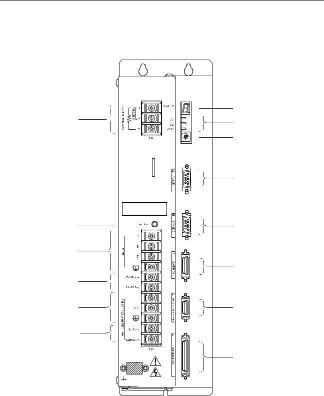
Pictorial Index
page 7-11
page 7-6
page 7-3
page 7-6
page 7-7
page 7-10
Shown here are face views of the product, with pointers to where individual parts are discussed.
Product Parts Explained (sheet 1 of 3)
WARNING: HIGH VOLTAGE |
MAY EXIST FOR UP TO FIVE MINUTES |
AFTER REMOVING POWER. |
page 10-1, 11-6
page 6-44
page 6-36
page 6-34
page 6-34
page 6-31
page 6-27
page 6-1
Models:
1398-DDM-010 and 1398-DDM-010X, 1398-DDM-020 and 1398-DDM-020X, 1398-DDM-030 and 1398-DDM-030X
Publication 1398-5.0 – October 1998
Intro-22 Preface
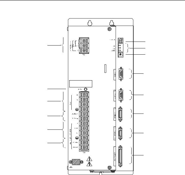
Product Parts Explained (sheet 2 of 3)
page 7-11
WARNING: HIGH VOLTAGE |
MAY EXIST FOR UP TO EIGHT MINUTES |
AFTER REMOVING POWER. |
page 7-6
page 7-3
page 7-6
page 7-7
page 7-10
Models:
1398-DDM-075 and 1398-DDM-075X
page 10-1, 11-6 page 6-44 page 6-36
page 6-34
page 6-34
page 6-31
page 6-27
page 6-1
Publication 1398-5.0 – October 1998
Preface Intro-23
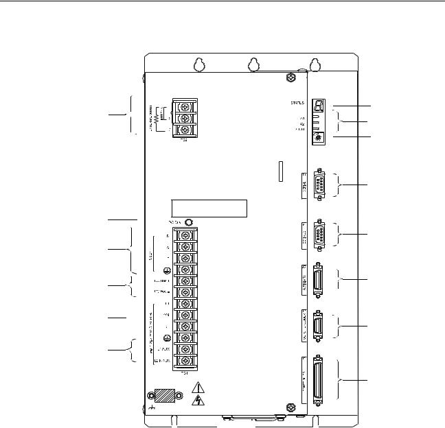
Product Parts Explained (sheet 3 of 3)
page 10-1, 11-6
page 7-11
page 6-44
page 6-36
page 6-34
WARNING: HIGH VOLTAGE
MAY EXIST FOR UP TO EIGHT MINUTES
AFTER REMOVING POWER.

page 7-6
page 6-34
page 7-3
page 6-31
page 7-6
page 7-7
page 6-27
page 7-10
page 6-1
Models:
1398-DDM-150 and 1398-DDM-150X
Publication 1398-5.0 – October 1998

Intro-24 Preface
Publication 1398-5.0 – October 1998
Chapter 1
Installing and Using the
ULTRA 200 Series
Safety
Read the complete manual before attempting to install or operate the ULTRA 200 Series drive. By reading the manual you will become familiar with practices and procedures that allow you to operate the ULTRA 200 Series drive safely and effectively.
Potential Hazards
The equipment described in this manual is intended for use in industrial drive systems. This equipment can endanger life through rotating machinery and high voltages, therefore it is essential that guards for both electrical and mechanical parts are not removed. The main hazards which can be encountered in the use of this equipment are:
●Electric shock hazards
●Electric fire hazards
●Mechanical hazards
●Stored energy hazards
These hazards must be controlled by suitable machine design, using the safety guidelines which follow. There are no chemical or ionizing radiation hazards.
Voltage Potentials
ATTENTION: DC bus capacitors may retain hazardous
!voltages for several minutes after input power has been removed, but will normally discharge in several seconds. Measure the DC bus voltage to verify it has reached a safe level each time power is removed before working on the
drive; or wait for the time indicated in the warning on the front of the drive. Failure to observe this precaution could result in severe bodily injury or loss of life.
Voltage potentials for the internal drive circuitry vary from 325 Volts above to 325 Volts below earth ground for a 240 Volt input. Voltages can exceed 450 VDC or 240 VAC within the ULTRA 200 Series. All circuits, including the connections on the front panel, should be considered “hot” when main or auxiliary power is connected and for the time specified in the warning on the front of the drive after power is removed.
Publication 1398-5.0 – October 1998
1-2 |
Safety |
Your Responsibilities
As the user or person installing this drive, you are responsible for determining the suitability of the product for the intended application. Rockwell Automation is neither responsible nor liable for indirect or consequential damage resulting from the inappropriate use of this product.
A qualified person is someone who is familiar with all safety notes and established safety practices, with the installation, operation and maintenance of this equipment and the hazards involved. For more detailed definitions, refer to IEC 364.
It is recommended that anyone who operates or maintains electrical or mechanical equipment should have a basic knowledge of First Aid. As a minimum, they should know where the First Aid equipment is kept and the identity of the official First Aiders.
Publication 1398-5.0 – October 1998
Safety |
1-3 |
Safety Guidelines
Electrical shock and fire hazards are avoided by using normal installation procedures for electrical power equipment in an industrial environment. Installation must be undertaken by suitably qualified personnel. Note that this amplifier must be installed in an industrial cabinet such that access is restricted to suitable qualified personnel.
Mechanical hazards are associated with potentially uncontrolled movement of the motor shaft. If this imposes a risk in the machine, then appropriate precautions must be made to electrically disconnect the motor from the drive when personnel have access to moving parts of the machine. Note also that the motor must be securely mounted at all times.
Stored energy hazards are both electrical and mechanical.
●Electrical hazards can be avoided by disconnecting the drive from its power source and measuring the DC bus voltage to verify it has reached a safe level or by waiting for the time indicated in the warning on the front of the drive prior to removing the protective covers or touching any connections.
●Mechanical hazards require a risk analysis on the effects of stored mechanical energy when the machine is running at speed, as well as the potential for the conversion of electrical energy stored in the drive being converted to mechanical energy. Electrical energy may be stored in drive for the time indicated in the warning on the front of the drive.
The following points should be observed for the safety of personnel. These safety notes do not represent a complete list of the steps necessary to ensure safe operation of the equipment. Contact your nearest Allen-Bradley representative for additional information.
●Only qualified personnel familiar with the equipment are permitted to install, operate and maintain the device.
●System documentation must be available and observed at all times.
●All non-qualified personnel are kept at a safe distance from the equipment.
●The system must be installed in accordance with local regulations.
●The equipment is intended for permanent connection to a main power input. It is not intended for use with a portable power input.
●Do not power up the unit without the covers in place and the protective conductor connected.
●Do not operate the unit without connecting the motor conductor to the appropriate terminal on the drive.
●Always remove power before making or removing any connection on the unit.
Publication 1398-5.0 – October 1998
1-4 |
Safety |
●Before removing the cover of the unit, shut off the main and auxiliary power and measure the DC bus voltage to verify it has reached a safe level or wait for the time indicated in the warning on the front of the drive.
●Do not make any connections to the internal circuitry. Connections on the front panel are the only points where users should make connections.
●
●
●
●
●
Be careful of the DC bus and shunt terminals. High voltage is present when power is applied to the ULTRA 200 Series.
Never connect the DCterminal to earth ground, the drive requires a floating DC bus.
Do not use the ENABLE input as a safety shutdown. Always remove power to the ULTRA 200 Series before maintaining or repairing the unit.
When operating a 1398-DDM-075 or 1398-DDM-075X with a single phase power input, the current limits must be set correctly.
Motors without thermal protection devices require a valid thermal time constant. Otherwise the motor overload protection will not function properly.
Publication 1398-5.0 – October 1998
Loading...