


 Loading...
User Manual
1732E ArmorBlock EtherNet/IP Dual Port 8-Point
Sequence of Events Input and Scheduled Output
Modules
Catalog Numbers 1732E-IB8M8SOER, 1732E-OB8M8SR

Important User Information
Solid-state equipment has operational characteristics differing from those of electromechanical equipment. Safety Guidelines for the Application, Installation and Maintenance of Solid State Controls (publication SGI-1.1 available from your local Rockwell Automation sales office or online at http://www.rockwellautomation.com/literature/) describes some important differences between solid-state equipment and hard-wired electromechanical devices. Because of this difference, and also because of the wide variety of uses for solid-state equipment, all persons responsible for applying this equipment must satisfy themselves that each intended application of this equipment is acceptable.
In no event will Rockwell Automation, Inc. be responsible or liable for indirect or consequential damages resulting from the use or application of this equipment.
The examples and diagrams in this manual are included solely for illustrative purposes. Because of the many variables and requirements associated with any particular installation, Rockwell Automation, Inc. cannot assume responsibility or liability for actual use based on the examples and diagrams.
No patent liability is assumed by Rockwell Automation, Inc. with respect to use of information, circuits, equipment, or software described in this manual.
Reproduction of the contents of this manual, in whole or in part, without written permission of Rockwell Automation, Inc., is prohibited.
Throughout this manual, when necessary, we use notes to make you aware of safety considerations.
WARNING: Identifies information about practices or circumstances that can cause an explosion in a hazardous environment, which may lead to personal injury or death, property damage, or economic loss.
ATTENTION: Identifies information about practices or circumstances that can lead to personal injury or death, property damage, or economic loss. Attentions help you identify a hazard, avoid a hazard, and recognize the consequence
SHOCK HAZARD: Labels may be on or inside the equipment, for example, a drive or motor, to alert people that dangerous voltage may be present.
BURN HAZARD: Labels may be on or inside the equipment, for example, a drive or motor, to alert people that surfaces may reach dangerous temperatures.
IMPORTANT Identifies information that is critical for successful application and understanding of the product.
Allen-Bradley, Rockwell Software, Rockwell Automation, ArmorBlock, RSLogix, RSLinx, and TechConnect are trademarks of Rockwell Automation, Inc.
Trademarks not belonging to Rockwell Automation are property of their respective companies.

Preface
Read this preface to familiarize yourself with the rest of the manual. It provides information concerning:
Who Should Use this Manual
Purpose of this Manual
•who should use this manual
•the purpose of this manual
•related documentation
•conventions used in this manual
Use this manual if you are responsible for designing, installing, programming, or troubleshooting control systems that 1732E ArmorBlock EtherNet/IP Dual Port 8-Point Sequence of Events Input and Scheduled Output Modules.
You should have a basic understanding of electrical circuitry and familiarity with relay logic. If you do not, obtain the proper training before using this product.
This manual is a reference guide for the 1732E-IB8M8SOER, 1732E-OB8M8SR modules. It describes the procedures you use to install, wire, troubleshoot, and use your module.
Related Documentation
The following documents contain additional information concerning Rockwell Automation products. To obtain a copy, contact your local Rockwell Automation office or distributor.
Resource |
Description |
|
|
ArmorBlock Dual-Port EtherNet/IP 8-Point Digital Modules |
Information on wiring the ArmorBlock Dual-Port EtherNet/IP 8-Point Digital |
1732E-WD002 |
Modules. |
|
|
1732E ArmorBlock 2 Port Ethernet Module Installation |
Information on installing the ArmorBlock EtherNet/IP module. |
Instructions, publication 1732E-IN007 |
|
|
|
1732E ArmorBlock 2 Port Ethernet Module Release Notes, |
Release notes to supplement the existing documentation supplied with the |
publication 1732E-RN001 |
ArmorBlock EtherNet/IP module. |
|
|
ControlLogix Sequence of Events Module User Manual, |
A manual on how to install, configure and troubleshoot the ControlLogix |
publication 1756-UM528 |
Sequence of Events module in your ControlLogix application. |
|
|
EtherNet/IP Embedded Switch Technology Application Guide, |
A manual on how to install, configure and maintain linear and Device-level |
publication ENET-AP005 |
Ring (DLR) networks using Rockwell Automation EtherNet/IP devices with |
|
embedded switch technology. |
|
|
EtherNet/IP Modules in Logix5000 Control Systems User |
A manual on how to use EtherNet/IP modules with Logix5000 controllers and |
Manual, publication ENET-UM001 |
communicate with various devices on the Ethernet network. |
|
|
Integrated Architecture and CIP Sync Configuration Application |
A manual on how to configure CIP Sync with Intergrated Architecture products. |
Techniques, publication IA-AT003 |
and applications. |
|
|
Getting Results with RSLogix 5000, publication |
Information on how to install and navigate RSLogix 5000. The guide includes |
9399-RLD300GR |
troubleshooting information and tips on how to use RSLogix 5000 effectively. |
|
|
Allen-Bradley Industrial Automation Glossary, AG-7.1 |
A glossary of industrial automation terms and abbreviations. |
|
|
Rockwell Automation Publication 1732E-UM003B-EN-E - March 2014 |
iii |

Common Techniques Used in this Manual
The following conventions are used throughout this manual:
•Bulleted lists such as this one provide information, not procedural steps.
•Numbered lists provide sequential steps or hierarchical information.
•Italic type is used for emphasis.
iv |
Rockwell Automation Publication 1732E-UM003B-EN-E - March 2014 |

New and Updated
Information
Summary of Changes
This manual contains new and updated information. Changes throughout this revision are marked by change bars, as shown to the right of this paragraph.
This table contains the changes made to this revision.
Topic |
Page |
|
|
Additional warning for I/O connectors |
20 |
|
|
Updated values of the following input specifications: |
93 |
•On-state current, min |
|
•Off-state current, max |
|
|
|
Publication 1732E-UM003B-EN-E - March 2014

vi Summary of Changes
Notes:
Publication 1732E-UM003B-EN-E - March 2014

Table of Contents
Preface
Who Should Use this Manual . . . . . . . . . . . . . . . . . . . . . . . . . . . . . . . . . . . . . . iii
Purpose of this Manual . . . . . . . . . . . . . . . . . . . . . . . . . . . . . . . . . . . . . . . . . . . . iii
Related Documentation. . . . . . . . . . . . . . . . . . . . . . . . . . . . . . . . . . . . . . . . iii
Common Techniques Used in this Manual . . . . . . . . . . . . . . . . . . . . . . . . . . iv
Chapter 1
About ArmorBlock Modules Overview . . . . . . . . . . . . . . . . . . . . . . . . . . . . . . . . . . . . . . . . . . . . . . . . . . . . . . . . . 1
Module Features . . . . . . . . . . . . . . . . . . . . . . . . . . . . . . . . . . . . . . . . . . . . . . . . . . 1
Hardware/Software Compatibility. . . . . . . . . . . . . . . . . . . . . . . . . . . . . . . . . . 1
Use of the Common Industrial Protocol (CIP) . . . . . . . . . . . . . . . . . . . . . . 2
Understand the Producer/Consumer Model. . . . . . . . . . . . . . . . . . . . . . . . . 2
Specify the Requested Packet Interval (RPI) . . . . . . . . . . . . . . . . . . . . . . . . . 2
Chapter Summary and What’s Next . . . . . . . . . . . . . . . . . . . . . . . . . . . . . . . . 3
Chapter 2
Module Overview and Features Overview . . . . . . . . . . . . . . . . . . . . . . . . . . . . . . . . . . . . . . . . . . . . . . . . . . . . . . . . . 5 EtherNet/IP Network Overview . . . . . . . . . . . . . . . . . . . . . . . . . . . . . . . . . . . 6 Introduction to CIP Sync . . . . . . . . . . . . . . . . . . . . . . . . . . . . . . . . . . . . . . . . . . 7 What is IEEE 1588 PTP (Precision Time Protocol)? . . . . . . . . . . . . . 7 CIP Sync Support . . . . . . . . . . . . . . . . . . . . . . . . . . . . . . . . . . . . . . . . . . . . . 7 What is CIP Sync?. . . . . . . . . . . . . . . . . . . . . . . . . . . . . . . . . . . . . . . . . . . . . 8 What is Time Stamping? . . . . . . . . . . . . . . . . . . . . . . . . . . . . . . . . . . . . . . . 8 Introduction to the Sequence of Events Input Module. . . . . . . . . . . . . . . . 8
High Performance Sequence of Events Applications in the Logix Architecture . . . . . . . . . . . . . . . . . . . . . . . . . . . . . . . . . . . . . . . . . . . . . . . . . . 9 First Fault Detection. . . . . . . . . . . . . . . . . . . . . . . . . . . . . . . . . . . . . . . . . . 10 Time Stamped I/O . . . . . . . . . . . . . . . . . . . . . . . . . . . . . . . . . . . . . . . . . . . 10 High Speed Applications . . . . . . . . . . . . . . . . . . . . . . . . . . . . . . . . . . . . . . 10 Motion Control . . . . . . . . . . . . . . . . . . . . . . . . . . . . . . . . . . . . . . . . . . . . . . 11 Global Position Registration. . . . . . . . . . . . . . . . . . . . . . . . . . . . . . . . . . . 11
Introduction to Scheduled Output Module. . . . . . . . . . . . . . . . . . . . . . . . . 11 Operation. . . . . . . . . . . . . . . . . . . . . . . . . . . . . . . . . . . . . . . . . . . . . . . . . . . . 11 High Speed Product Reject . . . . . . . . . . . . . . . . . . . . . . . . . . . . . . . . . . . . 12
Chapter Summary and What’s Next . . . . . . . . . . . . . . . . . . . . . . . . . . . . . . . 13
Chapter 3
Use the Modules in an
ArmorBlock System
Introduction . . . . . . . . . . . . . . . . . . . . . . . . . . . . . . . . . . . . . . . . . . . . . . . . . . . . . 15
Differences Between Module and Standard I/O. . . . . . . . . . . . . . . . . . . . . 15 Similar Functionality to Standard ArmorBlock . . . . . . . . . . . . . . . . . . . . . 15
Chapter Summary and What’s Next . . . . . . . . . . . . . . . . . . . . . . . . . . . . . . . 16
|
Chapter 4 |
|
Install Your Module |
Overview . . . . . . . . . . . . . . . . . . . . . . . . . . . . . . . . . . . . . . . . . . . . . . . . . . . . . . . . |
17 |
|
Install the Module . . . . . . . . . . . . . . . . . . . . . . . . . . . . . . . . . . . . . . . . . . . . . . . . |
17 |
Rockwell Automation Publication 1732E-UM003B-EN-E - March 2014

viii Table of Contents
Configure the Module for Your EtherNet/IP Network
Configure the Module Using
RSLogix 5000 Software
Common Features of the 1732E-IB8M8SOER and 1732E-OB8M8SR Modules
Set the Network Address . . . . . . . . . . . . . . . . . . . . . . . . . . . . . . . . . . . . . . 17
Mount the Module . . . . . . . . . . . . . . . . . . . . . . . . . . . . . . . . . . . . . . . . . . . . . . . 18
Wire the Module . . . . . . . . . . . . . . . . . . . . . . . . . . . . . . . . . . . . . . . . . . . . . . . . . 19
Power Connectors . . . . . . . . . . . . . . . . . . . . . . . . . . . . . . . . . . . . . . . . . . . . 20
Chapter Summary and What’s Next . . . . . . . . . . . . . . . . . . . . . . . . . . . . . . . 22
Chapter 5
Introduction . . . . . . . . . . . . . . . . . . . . . . . . . . . . . . . . . . . . . . . . . . . . . . . . . . . . . 23 Configuration Requirements . . . . . . . . . . . . . . . . . . . . . . . . . . . . . . . . . . . . . . 23
IP Address . . . . . . . . . . . . . . . . . . . . . . . . . . . . . . . . . . . . . . . . . . . . . . . . . . . 24
Gateway Address . . . . . . . . . . . . . . . . . . . . . . . . . . . . . . . . . . . . . . . . . . . . . 25 Subnet Mask . . . . . . . . . . . . . . . . . . . . . . . . . . . . . . . . . . . . . . . . . . . . . . . . . 26
Set the Network Address. . . . . . . . . . . . . . . . . . . . . . . . . . . . . . . . . . . . . . . . . . 27
Use the Rockwell Automation BootP/DHCP Utility . . . . . . . . . . . . . . . 27
Save the Relation List . . . . . . . . . . . . . . . . . . . . . . . . . . . . . . . . . . . . . . . . . 30 Use DHCP Software to Configure Your Module . . . . . . . . . . . . . . . . . . . 30 Chapter Summary and What’s Next . . . . . . . . . . . . . . . . . . . . . . . . . . . . . . . 31
Chapter 6
Introduction . . . . . . . . . . . . . . . . . . . . . . . . . . . . . . . . . . . . . . . . . . . . . . . . . . . . . 33 Set Up the Hardware . . . . . . . . . . . . . . . . . . . . . . . . . . . . . . . . . . . . . . . . . . . . . 34 Create the
Example Application . . . . . . . . . . . . . . . . . . . . . . . . . . . . . . . . . . . . . . . . . . . . . 35 Configure Your I/O Module . . . . . . . . . . . . . . . . . . . . . . . . . . . . . . . . . . . . . . 35 RSLogix 5000 Configuration Software . . . . . . . . . . . . . . . . . . . . . . . . . 36 Overview of the Configuration Process through RSLogix 5000. . . . . . . 36 Add a New Bridge and Module to Your RSLogix 5000 Project . . . . . . . 36 Add the Local EtherNet/IP Bridge to the I/O Configuration . . . . 37 Add the I/O module as a child of the 1756-EN2T module . . . . . . . 38
Use the Default Configuration . . . . . . . . . . . . . . . . . . . . . . . . . . . . . . . . . . . . 41
Change the Default Configuration. . . . . . . . . . . . . . . . . . . . . . . . . . . . . . . . . 41 Download Your Configuration . . . . . . . . . . . . . . . . . . . . . . . . . . . . . . . . . . . . 43 Edit Your Configuration. . . . . . . . . . . . . . . . . . . . . . . . . . . . . . . . . . . . . . . . . . 43 Access Module Data in RSLogix 5000 Software . . . . . . . . . . . . . . . . . . . . . 45
Configure RSLogix 5000 and the 1756-EN2T Communication Module for CIP Sync . . . . . . . . . . . . . . . . . . . . . . . . . . . . . . . . . . . . . . . . . . . . . . . . . . . . . 46 Chapter Summary and What’s Next . . . . . . . . . . . . . . . . . . . . . . . . . . . . . . . 46
Chapter 7
Introduction . . . . . . . . . . . . . . . . . . . . . . . . . . . . . . . . . . . . . . . . . . . . . . . . . . . . . 47 Communications Format . . . . . . . . . . . . . . . . . . . . . . . . . . . . . . . . . . . . . . . . 47 Electronic Keying . . . . . . . . . . . . . . . . . . . . . . . . . . . . . . . . . . . . . . . . . . . . . . . . 48 Module Inhibiting. . . . . . . . . . . . . . . . . . . . . . . . . . . . . . . . . . . . . . . . . . . . . . . . 49 Module Fault Reporting . . . . . . . . . . . . . . . . . . . . . . . . . . . . . . . . . . . . . . . . . . 50 Fully Configurable via Software . . . . . . . . . . . . . . . . . . . . . . . . . . . . . . . . . . . 50
Rockwell Automation Publication 1732E-UM003B-EN-E - March 2014

Table of Contents |
ix |
|
|
Specific Features of the
1732E-IB8M8SOER Sequence of
Events Input Module
Specific Features of the
1732E-OB8M8SR Scheduled
Output Module
Use the Sequence of Events
Input and Scheduled Output
Modules
Producer/Consumer Model . . . . . . . . . . . . . . . . . . . . . . . . . . . . . . . . . . . . . . . 51
Status Indicator Information . . . . . . . . . . . . . . . . . . . . . . . . . . . . . . . . . . . . . . 51
Agency Certifications. . . . . . . . . . . . . . . . . . . . . . . . . . . . . . . . . . . . . . . . . . . . . 51
Chapter Summary and What’s Next . . . . . . . . . . . . . . . . . . . . . . . . . . . . . . . 51
Chapter 8
Introduction . . . . . . . . . . . . . . . . . . . . . . . . . . . . . . . . . . . . . . . . . . . . . . . . . . . . . 53
Determine Module Compatibility . . . . . . . . . . . . . . . . . . . . . . . . . . . . . . . . . 53
Operational Modes . . . . . . . . . . . . . . . . . . . . . . . . . . . . . . . . . . . . . . . . . . . . . . . 53 Timestamp Latching . . . . . . . . . . . . . . . . . . . . . . . . . . . . . . . . . . . . . . . . . . . . . 54
Software Configurable Input Filters. . . . . . . . . . . . . . . . . . . . . . . . . . . . . . . . 55
Sync to Master . . . . . . . . . . . . . . . . . . . . . . . . . . . . . . . . . . . . . . . . . . . . . . . . . . . 57 Chapter Summary and What’s Next . . . . . . . . . . . . . . . . . . . . . . . . . . . . . . . 58
Chapter 9
Introduction . . . . . . . . . . . . . . . . . . . . . . . . . . . . . . . . . . . . . . . . . . . . . . . . . . . . . 59
Operational Modes . . . . . . . . . . . . . . . . . . . . . . . . . . . . . . . . . . . . . . . . . . . . . . . 60
Time-Scheduled Output Control . . . . . . . . . . . . . . . . . . . . . . . . . . . . . . 60
Configurable Point-Level Output Fault States . . . . . . . . . . . . . . . . . . . . . . 61
Output State . . . . . . . . . . . . . . . . . . . . . . . . . . . . . . . . . . . . . . . . . . . . . . . . . 62
Chapter Summary and What’s Next . . . . . . . . . . . . . . . . . . . . . . . . . . . . . . . 62
Chapter 10
Introduction . . . . . . . . . . . . . . . . . . . . . . . . . . . . . . . . . . . . . . . . . . . . . . . . . . . . . 63
Overview . . . . . . . . . . . . . . . . . . . . . . . . . . . . . . . . . . . . . . . . . . . . . . . . . . . . . . . . 64 Use the Sequence of Events Input Module. . . . . . . . . . . . . . . . . . . . . . . . . . 65
How Does 1732E-IB8M8SOER Store Timestamp Data?. . . . . . . . 65
Use Timestamp Latching. . . . . . . . . . . . . . . . . . . . . . . . . . . . . . . . . . . . . . 66 Use Timestamp Capture . . . . . . . . . . . . . . . . . . . . . . . . . . . . . . . . . . . . . . 67
Operational Modes . . . . . . . . . . . . . . . . . . . . . . . . . . . . . . . . . . . . . . . . . . . 68
Manage the Data . . . . . . . . . . . . . . . . . . . . . . . . . . . . . . . . . . . . . . . . . . . . . 73
Module Sends Data to the Controller . . . . . . . . . . . . . . . . . . . . . . . . . . 74
Copy Relevant Input Data to a Separate Data Structure. . . . . . . . . . 74
Acknowledge Timestamp Latching Timestamp Data . . . . . . . . . . . . 76 Sort the Data . . . . . . . . . . . . . . . . . . . . . . . . . . . . . . . . . . . . . . . . . . . . . . . . . 77
Clear All Data From the Module Buffer At Once. . . . . . . . . . . . . . . . 78
Propagate a Signal From Input Pin to EtherNet . . . . . . . . . . . . . . . . . 78 Per Point Mode of Operation. . . . . . . . . . . . . . . . . . . . . . . . . . . . . . . . . . 80
Use the Scheduled Output Module . . . . . . . . . . . . . . . . . . . . . . . . . . . . . . . . 81
Usage with MAOC Instruction. . . . . . . . . . . . . . . . . . . . . . . . . . . . . . . . 81 I/O Subsystem . . . . . . . . . . . . . . . . . . . . . . . . . . . . . . . . . . . . . . . . . . . . . . . 83 Schedule Processing. . . . . . . . . . . . . . . . . . . . . . . . . . . . . . . . . . . . . . . . . . . 84 Chapter Summary and What’s Next . . . . . . . . . . . . . . . . . . . . . . . . . . . . . . . 85
Chapter 11
Rockwell Automation Publication 1732E-UM003B-EN-E - March 2014

x |
Table of Contents |
|
|
Troubleshoot the Module |
Troubleshoot the Module. . . . . . . . . . . . . . . . . . . . . . . . . . . . . . . . . . . . . . . . |
. 87 |
|
|
|
Determine Fault Type . . . . . . . . . . . . . . . . . . . . . . . . . . . . . . . . . . . . . . . . |
89 |
|
|
Chapter Summary . . . . . . . . . . . . . . . . . . . . . . . . . . . . . . . . . . . . . . . . . . . . . . . . |
89 |
|
|
Chapter 12 |
|
Interpret Status Indicators |
Introduction . . . . . . . . . . . . . . . . . . . . . . . . . . . . . . . . . . . . . . . . . . . . . . . . . . . . . |
91 |
|
|
|
Chapter Summary and What’s Next . . . . . . . . . . . . . . . . . . . . . . . . . . . . . . . |
92 |
|
|
Appendix A |
|
Specifications |
Specifications . . . . . . . . . . . . . . . . . . . . . . . . . . . . . . . . . . . . . . . . . . . . . . . . . . . . |
93 |
|
|
|
Appendix B |
|
Module Tags |
Fault and Status Reporting Between the Module and Controllers. . . . . |
97 |
|
|
|
Module Tag Names and Definitions . . . . . . . . . . . . . . . . . . . . . . . . . . . . . . . |
97 |
|
|
Tags Used. . . . . . . . . . . . . . . . . . . . . . . . . . . . . . . . . . . . . . . . . . . . . . . . . . . . |
97 |
|
|
Appendix C |
|
Data Tables |
Communicate with Your Module. . . . . . . . . . . . . . . . . . . . . . . . . . . . . . . . . |
105 |
|
|
|
Connection Points. . . . . . . . . . . . . . . . . . . . . . . . . . . . . . . . . . . . . . . . . . . |
105 |
|
|
Appendix D |
|
Connect to Networks via |
ArmorBlock Module and Ethernet Communication . . . . . . . . . . . . . . . |
119 |
|
Ethernet Interface |
ArmorBlock module and PC Connections to the Ethernet Network. 119 |
||
|
|
Ethernet Network Topology . . . . . . . . . . . . . . . . . . . . . . . . . . . . . . . . . |
119 |
|
|
Connecting to an Ethernet Network . . . . . . . . . . . . . . . . . . . . . . . . . . |
120 |
|
|
Cables . . . . . . . . . . . . . . . . . . . . . . . . . . . . . . . . . . . . . . . . . . . . . . . . . . . . . . |
120 |
|
|
EtherNet/IP Connections . . . . . . . . . . . . . . . . . . . . . . . . . . . . . . . . . . . . . . . |
120 |
|
|
Duplicate IP Address Detection . . . . . . . . . . . . . . . . . . . . . . . . . . . . . . . . . . |
121 |
|
|
Configure Ethernet Communications on the ArmorBlock module . . |
121 |
|
|
Configure Using |
|
|
|
RSLogix 5000 Software . . . . . . . . . . . . . . . . . . . . . . . . . . . . . . . . . . . . . . . . . . |
122 |
|
|
Configure Using Web Server . . . . . . . . . . . . . . . . . . . . . . . . . . . . . . . . . . . . . |
122 |
Appendix E
1732E ArmorBlock Embedded Introduction . . . . . . . . . . . . . . . . . . . . . . . . . . . . . . . . . . . . . . . . . . . . . . . . . . . . 123
Web Server Typical Applications. . . . . . . . . . . . . . . . . . . . . . . . . . . . . . . . . . . . . . . . . . . . . 123
Browser Requirements . . . . . . . . . . . . . . . . . . . . . . . . . . . . . . . . . . . . . . . . . . . 123
Access the Home Page of the Web Server. . . . . . . . . . . . . . . . . . . . . . . . . . 124 Log On to the Web Server . . . . . . . . . . . . . . . . . . . . . . . . . . . . . . . . . . . . . . . 124
Navigate the 1732E ArmorBlock I/O . . . . . . . . . . . . . . . . . . . . . . . . . . . . . 125
Access Diagnostic Information . . . . . . . . . . . . . . . . . . . . . . . . . . . . . . . . . . . 125
Index
Rockwell Automation Publication 1732E-UM003B-EN-E - March 2014
Chapter 1
Overview
Module Features
Hardware/Software
Compatibility
About ArmorBlock Modules
This chapter is an overview of the ArmorBlock family of modules. You will need to understand the concepts discussed in this chapter to configure your module and use it in an EtherNet/IP control system. The following table guides you where to find specific information in this chapter.
Topic |
Page |
|
|
Module Features |
1 |
|
|
Hardware/Software Compatibility |
1 |
|
|
Use of the Common Industrial Protocol (CIP) |
2 |
|
|
Understand the Producer/Consumer Model |
2 |
|
|
Specify the Requested Packet Interval (RPI) |
2 |
|
|
The module features include:
•use of EtherNet/IP messages encapsulated within standard TCP/UDP/IP protocol
•common application layer with ControlNet and DeviceNet
•interfacing via Category 5 rated twisted pair cable
•half/full duplex 10 Mbit or 100 Mbit operation
•mounting on a wall or panel
•communication supported by RSLinx software
•IP address assigned via standard DHCP tools
•I/O configuration via RSLogix 5000 software
•no network scheduling required
•no routing tables required
•supports connections from multiple controllers simultaneously
The module and the applications described in this manual are compatible with the following firmware versions and software releases.
Contact Rockwell Automation if you need software or firmware upgrades to use this equipment.
Product |
Firmware Version / Software Release |
|
|
1732E-IB8M8SOER and 1732E-OB8M8SR |
Firmware rev. 1.1 or later |
|
|
Rockwell Automation Publication 1732E-UM003B-EN-E - March 2014 |
1 |

Chapter 1 About ArmorBlock Modules
Product |
Firmware Version / Software Release |
|
|
1756-EN2T, 1756-EN2TR, 1756-EN3TR |
3.x version when using RSLogix 5000 v18 or later |
|
|
RSLogix 5000 software |
18 or later |
|
|
RSLinx software |
2.56 or later |
|
|
For a complete ControlLogix compatibility matrix, see publication IA-AT003.
Use of the Common
Industrial Protocol (CIP)
Understand the Producer/
Consumer Model
Specify the Requested
Packet Interval (RPI)
The 1732E-IB8M8SOER and 1732E-OB8M8SR modules use the Common Industrial Protocol (CIP). CIP is the application layer protocol specified for EtherNet/IP, the Ethernet Industrial Protocol. It is a message-based protocol that implements a relative path to send a message from the “producing” device in a system to the “consuming” devices.
The producing device contains the path information that steers the message along the proper route to reach its consumers. Because the producing device holds this information, other devices along the path simply pass this information; they do not need to store it.
This has two significant benefits:
•You do not need to configure routing tables in the bridging modules, which greatly simplifies maintenance and module replacement.
•You maintain full control over the route taken by each message, which enables you to select alternative paths for the same end device.
The CIP “producer/consumer” networking model replaces the old source/ destination (“master/slave”) model. The producer/consumer model reduces network traffic and increases speed of transmission. In traditional I/O systems, controllers poll input modules to obtain their input status. In the CIP system, input modules are not polled by a controller. Instead, they produce their data either upon a change of state (CoS) or periodically. The frequency of update depends upon the options chosen during configuration and where on the network the input module resides. The input module, therefore, is a producer of input data and the controller is a consumer of the data.
The controller can also produce data for other controllers to consume. The produced and consumed data is accessible by multiple controllers and other devices over the EtherNet/IP network. This data exchange conforms to the producer/consumer model.
The Requested Packet Interval (RPI) is the update rate specified for a particular piece of data on the network. This value specifies how often to produce the data for that device. For example, if you specify an RPI of 50 ms, it means that every
2 |
Rockwell Automation Publication 1732E-UM003B-EN-E - March 2014 |

About ArmorBlock Modules |
Chapter 1 |
|
|
Chapter Summary and
What’s Next
50 ms the device sends its data to the controller or the controller sends its data to the device.
RPIs are only used for devices that exchange data. For example, a ControlLogix EtherNet/IP bridge module in the same chassis as the controller does not require an RPI because it is not a data-producing member of the system; it is used only as a bridge to remote modules.
In this chapter you were given an overview of the 1732E ArmorBlock family of modules.
Rockwell Automation Publication 1732E-UM003B-EN-E - March 2014 |
3 |

Chapter 1 About ArmorBlock Modules
Notes:
4 |
Rockwell Automation Publication 1732E-UM003B-EN-E - March 2014 |

Chapter 2
Module Overview and Features
Overview
This chapter provides an overview of the 1732E ArmorBlock EtherNet/IP Dual Port 8-Point Sequence of Events Input and Scheduled Output Modules, 1732E-IB8M8SOER and 1732E-OB8M8SR. The modules provide timestamping functionality when an input event occurs and allow for scheduling of outputs.
Although primarily described in this manual as having CIP Sync functionality, both modules can be configured to function as standard I/O modules.
The following table indicates where you can information on this chapter:
Topic |
Page |
|
|
EtherNet/IP Network Overview |
6 |
|
|
Introduction to CIP Sync |
7 |
|
|
What is IEEE 1588 PTP (Precision Time Protocol)? |
7 |
|
|
CIP Sync Support |
7 |
|
|
What is CIP Sync? |
8 |
|
|
What is Time Stamping? |
8 |
|
|
Introduction to the Sequence of Events Input Module |
8 |
|
|
High Performance Sequence of Events Applications in the Logix Architecture |
9 |
|
|
First Fault Detection |
10 |
|
|
High Speed Applications |
10 |
|
|
Motion Control |
11 |
|
|
Global Position Registration |
11 |
|
|
Introduction to Scheduled Output Module |
11 |
|
|
Operation |
11 |
|
|
High Speed Product Reject |
12 |
|
|
Rockwell Automation Publication 1732E-UM003B-EN-E - March 2014 |
5 |
Chapter 2 Module Overview and Features
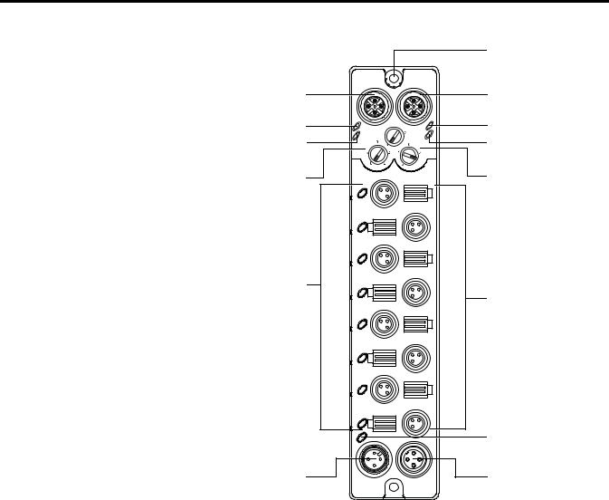
EtherNet/IP
Network Overview
EtherNet/IP D-Code
M12 connector
Link 1 status LED
Module status LED
Node address switches
LINK1 |
LINK2 |
|
X10 |
MOD |
NET |
|
X100
 X1
X1
Functional Earth ground(1)
EtherNet/IP D-Code M12 connector
Link 2 status LED Network status LED
Node address switches
M8 I/O connectors/ |
M8 I/O connectors |
status indicators |
Power status indicator
Power connector |
Power connector |
45766
(1)Functional Earth grounds the I/O block’s EtherNet/IP communication circuitry which is designed to mitigate the effect of noise on the network. It requires a solid earth ground connection, either through a metal screw to a grounded metal panel or through a wire.
The modules incorporate embedded switch technology. They support Star, Tree, Daisychain or Linear, and Ring network topologies.
•Star or Tree topologies can connect to either Port 1 or Port 2.
•Daisy Chain/Linear topologies will pass communications from Port 1 to 2, or Port 2 to 1.
•Ring topology will pass communications from Port 1 to 2, or Port 2 to 1.
The 1732E-IB8M8SOER and 1732E-OB8M8SR modules support the management of network traffic to ensure timely delivery of critical data, Quality of Service (QoS) and Internet Group Management Protocol (IGMP) protocols are supported.
6 |
Rockwell Automation Publication 1732E-UM003B-EN-E - March 2014 |

Module Overview and Features Chapter 2
|
If the ring topology is used, the Ring Master (not the 1732E ArmorBlock |
|
EtherNet/IP Dual Port 8-Point Sequence of Events Input or Scheduled Output) |
|
must be designated in the system, and determines the beacon rate and the timeout |
|
period. For more information on topologies, refer to publication ENET-AP005. |
|
The 1732E-IB8M8SOER and 1732E-OB8M8SR modules are CIP Sync slave |
|
only devices. There must be another module on the network that functions as a |
|
master clock. |
Introduction to CIP Sync |
CIP is the Common Industrial Protocol that we use to let all |
|
Rockwell Automation products communicate with each other whether it be on a |
|
DeviceNet, ControlNet, and/or an EtherNet network. Since it is an ODVA |
|
standard, other industrial product manufacturers develop products to |
|
communicate via the CIP protocol. |
|
CIP Sync is a CIP implementation of the IEEE 1588 PTP (Precision Time |
|
Protocol) in which devices can bridge the PTP time across backplanes and on to |
|
other networks via EtherNet/IP ports. |
|
What is IEEE 1588 PTP (Precision Time Protocol)? |
|
The IEEE 1588 standard specifies a protocol to synchronize independent clocks |
|
running on separate nodes of a distributed measurement and control system to a |
|
high degree of accuracy and precision. The clocks communicate with each other |
|
over a communication network. In its basic form, the protocol is intended to be |
|
administration free. The protocol generates a master slave relationship among the |
|
clocks in the system. Within a given subnet of a network there will be a single |
|
master clock. All clocks ultimately derive their time from a clock known as the |
|
grandmaster clock. This is called Precision Time Protocol (PTP). |
|
The PTP is a time-transfer protocol defined in the IEEE 1588-2008 standard |
|
that allows precise synchronization of networks, for example, Ethernet. Accuracy |
|
within the nanosecond range can be achieved with this protocol when using |
|
hardware generated synchronization. |
|
IEEE 1588 is designed for local systems requiring very high accuracies beyond |
|
those attainable using Network Time Protocol (NTP). NTP is used to |
|
synchronize the time of a computer client or server to another server or reference |
|
time source, such as a GPS. |
|
CIP Sync Support |
|
CIP Sync supports the IEEE 1588-2008 synchronization standard. In this |
|
architecture, a grandmaster clock provides a master time reference for the system |
|
time. The 1732E-IB8M8SOER, 1732E-OB8M8SR modules are CIP Sync slave |
Rockwell Automation Publication 1732E-UM003B-EN-E - March 2014 |
7 |

Chapter 2 Module Overview and Features
Introduction to the Sequence of Events Input Module
only devices. There must be another module on the network that will function as a master clock. The grandmaster could be:
•a 1756 ControlLogix L6 or L7 controller when using RSLogix 5000 software v18 or later.
•an Ethernet bridge that supports IEEE 1588 V2, or
•a Symmetricom Grand Master GPS or equivalent.
What is CIP Sync?
CIP Sync is a CIP implementation of the IEEE 1588 PTP (Precision Time Protocol). CIP Sync provides accurate real-time (Real-World Time) or Universal Coordinated Time (UTC) synchronization of controllers and devices connected over CIP networks. This technology supports highly distributed applications that require time stamping, sequence of events recording, distributed motion control, and increased control coordination.
What is Time Stamping?
Each input has its own individual timestamp recorded for both ON and OFF transitions. The offset from the timestamp to the local clock is also recorded so that steps in time can be detected and resolved.
Timestamping uses the 64-bit system time whose time base is determined by the modules master clock resolved in microseconds. Each timestamp is updated as soon as an input transition is detected, before input filtering occurs. When filtering is enabled, the transition is only recorded if the transition passes the filter.
The module starts timestamping as soon as it powers up, even if it is not synchronized to a master clock. If it is synchronized to a master clock and then becomes unsynchronized it continues to time stamp. All time stamps and offsets have a value of zero at power-up.
For more information on how to use CIP Sync technology, see the Integrated Architecture and CIP Sync Configuration Application Technique publication IA-AT003.
The 1732E-IB8M8SOER is an input module that offers sub-millisecond timestamping on a per point basis in addition to providing the basic ON/OFF detection. It supports two modes of operation: Per Point Mode and FIFO (First In First Out) Mode. To learn more about using the modules in these modes of operation, see Operational Modes on page 68.
8 |
Rockwell Automation Publication 1732E-UM003B-EN-E - March 2014 |

Module Overview and Features |
Chapter 2 |
|
|
All input point event times are recorded and returned in a single buffer. The module returns two 64-bit timestamps for each input, thus allowing:
•ON and OFF events for each point to be displayed simultaneously in the input data.
•ladder logic not being explicitly required to see events, although needed to archive events.
•events to be kept in the controller memory during remote power loss thus eliminating data loss.
All inputs on the module can be filtered for both ON to OFF and OFF to ON transitions. The timestamp for a filtered input will be the time of the initial transition to the new state and not the time that the filter validates the event as real.
Selective Event Capturing allows particular events to be disabled per input and per transition, ON to OFF or OFF to ON.
Event latching ensures that events are not overwritten. A single transition in each direction is recorded per point. Any new event, which occurs after the point has captured a timestamp, is dropped until the stored events have been acknowledged.
If latching is not enabled in point mode, new events will overwrite old events when they are received. In FIFO mode, up to 256 events per input will be buffered before events are overwritten. Thus, if inputs are changing rapidly it may be possible that events will be lost either in the module or the controller prior to an event being operated on by ladder logic.
When events are lost, either old ones being overwritten or new ones being ignored due to latching, an EventOverflow bit will be set for each point that loses an event. The EventOverflow bit will clear when the blocking events for that point are acknowledged.
Timestamping is a feature that registers a time reference to a change in input data. For the 1732E-IB8M8SOER, the time mechanism used for timestamping is (PTP) system time. The 1732E-IB8M8SOER module is a PTP slave-only device. There must be another module on the network that functions as a master clock.
High Performance Sequence of Events Applications in the Logix
Architecture
Sequence of Events (SOE) applications span a wide range of industry applications. Typically any event that needs to be compared against a second event can be classified as SOE.
•Used on discrete machines to identify failure points
•Used in Power Substations or power plants to indicate first fault conditions
Rockwell Automation Publication 1732E-UM003B-EN-E - March 2014 |
9 |

Chapter 2 Module Overview and Features
•Used in SCADA applications to indicate pump failures or other discrete events
•Used in motion control applications to increase control coordination.
•Used in high speed applications
•Used in Global Position Registration
In today's environment, specifications for SOE applications typically require 1 ms or better resolution on timestamps. There are two types of SOE applications.
•First Fault – measures the time between events with no correlation to events outside of that system.
•Real Time – captures the time of an event occurrence as it relates to some master clock. Typically this is a GPS, NTP server or some other very accurate clock source. This method allows distributed systems to capture events and build a history of these events. These events are almost always digital, however some are analog for which lower performance requirements can be configured.
First Fault Detection
An example of first fault detection would be intermittent failure from a sensor on a safety system faults a machine and halts production cascading a flood of other interrelated machine faults. Traditional fault detection or alarms may not appear in the correct timed order of actual failure making root cause of the down time difficult or impossible.
Time Stamped I/O
High precision timestamps on I/O allows very accurate first fault detection making it easy to identify the initial fault that caused machine down time.
Common Time base for Alarming System logs user interaction as well as alarm events using common time reference.
The power industry requires sub 1 ms accuracy on first fault across geographically dispersed architecture.
High Speed Applications
Packaging machines or sorters that have fast part cycles are often bottlenecked by controller scan times. By switching to a time-based solution, you can remove many scan time critical components of the system. This programming technique allows you to do predictive events and schedule outputs to run things like diverters without having a scan time to match the part cycle time.
10 |
Rockwell Automation Publication 1732E-UM003B-EN-E - March 2014 |
Module Overview and Features |
Chapter 2 |
|
|
Introduction to Scheduled Output Module
Motion Control
CIP Sync also provides a common time reference for distributed VFD drives, servos, and controllers throughout the system. This allows controllers to request axes, reach a pre-defined position at a known time reference, or run at a set speed using the same reference. Since all drives and controllers in the system have the same reference to time, the controller can issue simple requests for axes to reach target positions in a synchronized fashion.
Global Position Registration
Registration refers to a function usually performed by the drive where a physical input is triggered causing the drive to precisely capture the actual axis position when the input event occurred. Rather than wiring inputs to the registration input on all of the drives, this time-based system lets you wire an input to only one time based SOE input module. The timestamp returned for that input, can be used by the motion planner to calculate the actual axis position at the time the input triggered. This simplifies system installation, reduces wiring costs, and provides a global machine registration for all the axes in the system thru one SOE input.
The 1732E-OB8M8SR Scheduled Output module is designed to work in conjunction with the MAOC motion instruction to provide position-based output control (also known as PLS). The MAOC instruction by itself allows position-based output control using the position of any motion axis in ControlLogix as the position reference and any output or boolean as the output. The MAOC updates the outputs based on motion axis position at the motion group coarse update rate (typically 2…10 ms). While this is adequate for some applications, it is too slow for many high speed applications typically found in converting and packaging segments. The 1732E-OB8M8SR module improves performance by supporting the ability to schedule the output turn-on/turn- off time of its 8 outputs (outputs 0…7) in 1 µs increments. Outputs are scheduled by entering data into one or more of the 16 schedules provided by the output connection data store.
IMPORTANT When using the 1732E-OB8M8SR module with the MAOC instruction, make sure you use the default Communication Format for the module, that is, Schedule Output Data Per Point. If you change the Communication Format when the module is used with an MAOC instruction, an error may result.
Operation
This scheduled output implementation schedules outputs on a per point basis and each individual output point is controlled by its own timestamp.
Rockwell Automation Publication 1732E-UM003B-EN-E - March 2014 |
11 |
Chapter 2 Module Overview and Features
Individual schedules are created in the controller, stored in the output image table for the module, and sent over the backplane to the Scheduled Output module. The schedule specifies a sequence count, the output point to be associated with the schedule, the time at which an output value should be applied to the physical output point, and the value to be applied at the scheduled time. The I/O module receives and stores the schedule. The CIPSync time of each schedule is monitored by the module. When a schedule has expired, that is the current time, matches the scheduled timestamp, the output value is then applied to the corresponding output bit. Timer hardware in the ASIC is used to optimize the scheduling algorithm. This hardware also reduces the latency and jitter performance. Status of each schedule is reported in the output echo connection and reflected in the input image for the module.
The scheduled output functionality relies on CIPSync time. Unused outputs may be used as normal outputs and are applied immediately rather than waiting for the CIPSync time to expire. A mask is sent to the module to indicate which outputs are to function as normal outputs. The scheduled output module supports up to 8 outputs that can be individually scheduled. The scheduled outputs must be between output points 0 and 7. The 1732E-OB8M8SR module supports up to 16 schedules with two schedules per output. Outputs that are not “scheduled” are used as normal output points. A mask is used to indicate which points are scheduled and which points are unscheduled. Jitter performance is less than 25 µs. All of the scheduling configuration is done through the MAOC instruction.
If a new schedule as indicated by a change in the sequence count is received by the I/O module before the current schedule has expired, the current schedule is overwritten. This mechanism can be used to cancel currently active schedule. Status bits returned in the output echo connection may be used to determine the current state of each schedule and to trigger corresponding event tasks.
If a new schedule is sent by the controller and the CIPSync time has already past, the output is asserted until the CIPSync time has completely wrapped around. The module does not check for an expired CIPSync time.
WARNING: If the time between two schedules is less than the minimum schedule interval (for example, 100 µs), then deviation occurs. This means that even though two outputs are scheduled at different times (for example, time 90 and time 110), they both activate at the same time (for example, time 90). The minimum schedule interval should not be set to faster than 100 µs.
High Speed Product Reject
In a control system you can program a scheduled output module, which can trigger multiple outputs simultaneously or trigger a reject at the precise point a product is at the reject station.
12 |
Rockwell Automation Publication 1732E-UM003B-EN-E - March 2014 |

Module Overview and Features |
Chapter 2 |
|
|
Chapter Summary and
What’s Next
By using time to schedule the output in advance,and identifying when the product will be at a known position, hitting the exact point when a part is in front of a reject station on a high speed packaging machine, can be controlled.
In this chapter, you were given an overview of the 1732E ArmorBlock EtherNet/ IP Dual Port 8-Point Sequence of Events Input and Scheduled Output Modules modules. The next chapter describes how the modules operate in an ArmorBlock system.
Rockwell Automation Publication 1732E-UM003B-EN-E - March 2014 |
13 |

Chapter 2 Module Overview and Features
Notes:
14 |
Rockwell Automation Publication 1732E-UM003B-EN-E - March 2014 |

Chapter 3
Use the Modules in an ArmorBlock System
Introduction
This chapter describes how the 1732E ArmorBlock EtherNet/IP Dual Port 8- Point Sequence of Events Input and Scheduled Output Modules modules operate in an ArmorBlock system.
Topic |
Page |
|
|
Differences Between Module and Standard I/O |
15 |
|
|
Similar Functionality to Standard ArmorBlock |
15 |
|
|
Differences Between
Module and Standard I/O
In many aspects, the modules behave the same as any other ArmorBlock digital module. However, the modules offer several significant differences from other EtherNet/IP ArmorBlock digital input modules, including those described in the following table.
Difference |
Description |
|
|
Additional data produced for controller |
The modules produce significantly more data for its owner-controller than |
|
standard ArmorBlock digital input modules. While other input modules only |
|
produce ON/OFF and fault status, the modules produce data such as ON/ |
|
OFF and fault status, timestamp data, indication of whether new data was |
|
produced for specific input points or if transitions were not timestamped. |
|
|
CIP Sync |
These modules have an internal clock that is synchronized with a master |
|
clock using CIP Sync. This clock is used for time stamping inputs and |
|
outputs. |
|
|
Only one owner-controller per module |
While multiple controllers can simultaneously own other digital input |
|
modules, the module only supports a single owner-controller. |
|
|
Similar Functionality to Standard ArmorBlock
This chapter focuses on how the module behavior differs from that of other ArmorBlock modules. However, you should be aware of aspects in which the module is similar to standard EtherNet/IP ArmorBlock modules. The following table describes the similarities.
Concept |
Description |
|
|
Ownership |
Every module in an ArmorBlock system must be owned by a Logix5000 controller. This |
|
owner-controller: |
|
• stores configuration data for every module that it owns. |
|
• sends the module configuration data to define the module behavior and begin |
|
operation with the control system. |
|
This module does not support multiple owner-controllers. |
|
|
Rockwell Automation Publication 1732E-UM003B-EN-E - March 2014 |
15 |

Chapter 3 Use the Modules in an ArmorBlock System
Concept |
Description |
|
|
Using RSLogix 5000 software |
The I/O configuration portion of RSLogix 5000 software, v18 or greater, generates the |
|
configuration data for each module. |
|
Configuration data is transferred to the controller during the program download and |
|
subsequently transferred to the appropriate modules. |
|
Modules are ready to run as soon as the configuration data has been downloaded. |
|
Configure all modules for a given controller using RSLogix 5000 software and download |
|
that information to the controller. |
|
|
Chapter Summary and
What’s Next
In this chapter, you learned about the differences between this module and other EtherNet/IP ArmorBlock I/O modules. The next chapter describes how to install and wire your module.
16 |
Rockwell Automation Publication 1732E-UM003B-EN-E - March 2014 |

Chapter 4
Install Your Module
Overview
Install the Module
This chapter shows you how to install and wire the 1732E ArmorBlock EtherNet/IP Dual Port 8-Point Sequence of Events Input and Scheduled Output Modules modules. The only tools you require are a flat or Phillips head screwdriver and drill. This chapter includes the following topics:
Topic |
Page |
|
|
Install the Module |
17 |
|
|
Set the Network Address |
17 |
|
|
Mount the Module |
18 |
|
|
Wire the Module |
19 |
|
|
Power Connectors |
20 |
|
|
To install the module:
•Set the network address
•Mount the module
•Connect the I/O, Network, and Auxiliary cables to the module.
Set the Network Address
The I/O block ships with the rotary switches set to 999 and DHCP enabled. To change the network address, you can do one of the following:
•adjust the node address switches on the front of the module.
•use a Dynamic Host Configuration Protocol (DHCP) server, such as Rockwell Automation BootP/DHCP.
•retrieve the IP address from nonvolatile memory.
The I/O block reads the switches first to determine if the switches are set to a valid number. To set the network address:
1.Remove power.
2.Remove the switch dust caps.
3.Rotate the three (3) switches on the front of the module using a small blade screwdriver.
Rockwell Automation Publication 1732E-UM003B-EN-E - March 2014 |
17 |

Chapter 4 Install Your Module
4.Line up the small notch on the switch with the number setting you wish to use.
Valid settings range from 001…254.
5.Replace switch dust caps. Make sure not to over tighten.
6.Reapply power.
Mount the Module
To mount the module on a wall or panel, use the screw holes provided in the module. Refer to the drilling dimensions illustration to guide you in mounting the module.
Functional Earth
Grounds the I/O block EtherNet/IP communication circuitry which is designed to mitigate the effect of noise on the network. It requires a solid earth ground connection, either through a metal screw to a grounded metal panel or through a wire.
37 (1.46)
16.2 (0.64)
179 (7.05)
168.6 (6.64)
19.8 |
Millimeters |
(0.78) |
(Inches) |
|
166.5 (6.56) |
27 (1.06) |
|
Side Mounting
43.3 (1.70)
32 (1.26 ) |
18 (0.71) |
45765 |
Front Mounting
Install the mounting base as follows:
1.Lay out the required points as shown above in the drilling dimension drawing.
18 |
Rockwell Automation Publication 1732E-UM003B-EN-E - March 2014 |
Install Your Module |
Chapter 4 |
|
|
Wire the Module
2.Drill the necessary holes for #6 (M3) pan head screws.
3.Mount the module using #6 (M3) screws.
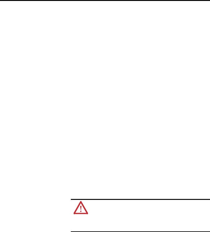
Mount the Module in High Vibration Areas
If you mount the module in an area that is subject to shock or vibration, we recommend you use a flat and a lock washer to mount the module. Mount the flat and the lock washer as shown in the mounting illustration. Torque the mounting screws to 0.68 Nm (6 lb-in.).
High Vibration Area Mounting
Lock washer
Flat washer
45768
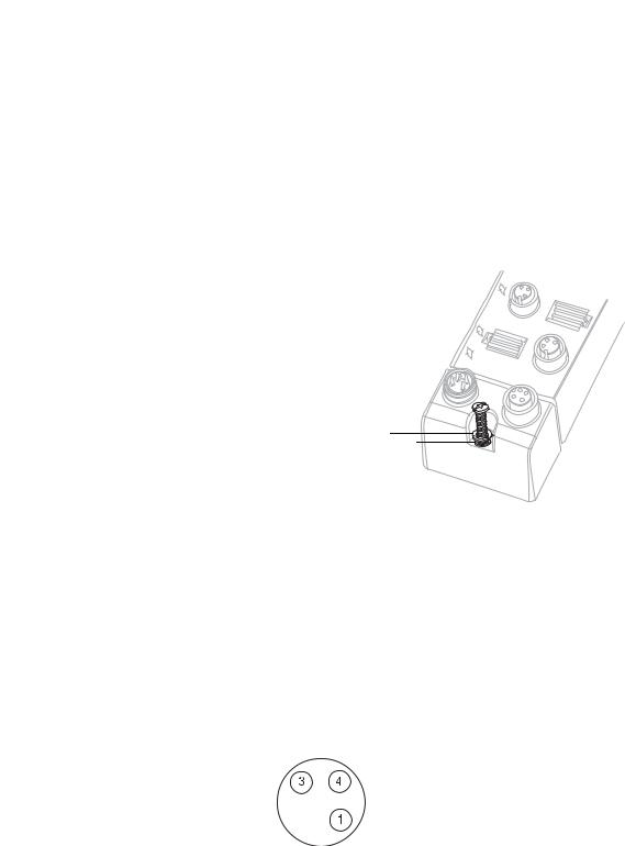
The 1732E-OB8M8SR and 1732E-IB8M8SOER ArmorBlock EtherNet/IP modules have 3-pin pico-style I/O connectors. We provide caps to cover the unused connectors on your module. Connect the quick-disconnect cord sets you selected for your module to the appropriate ports.
I/O Connectors
Refer to the pinout diagrams for the I/O connectors.
Pico-style 3-Pin Input Female Connector
(View into connector)
Pin 1 Sensor source voltage Pin 3 Return
Pin 4 Input
43583
Rockwell Automation Publication 1732E-UM003B-EN-E - March 2014 |
19 |
Chapter 4 Install Your Module
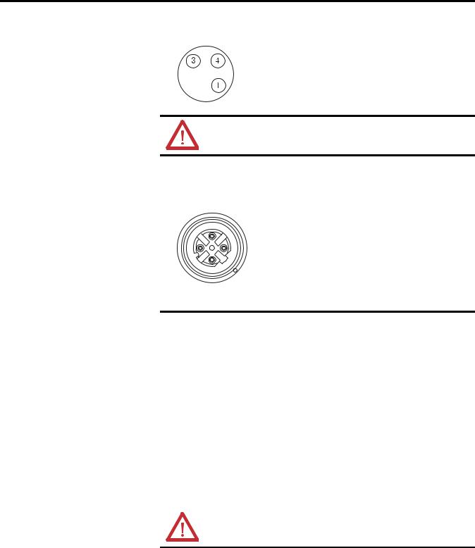
Pico-style 3-Pin Output Female Connector
(View into connector)
Pin 1 Sensor Source Voltage Pin 3 Return
Pin 4 Output
43583
ATTENTION: Sensors/actuators power should not be supplied externally.
Ethernet Connectors
Refer to the pinout diagrams for the network connectors.
|
4 |
|
(View into connector) |
|
|
|
Pin 1Tx+ |
||
|
|
|
Pin 2 Rx+ |
|
3 |
1 |
|
Pin 3 Tx- |
|
|
|
|
Pin 4 |
Rx- |
|
2 |
5 |
Pin 5 |
Shell |
|
|
44808 |
|
|
|
|
|
|
|
.
IMPORTANT |
Use the 1585D–M4DC–H: Polyamide small body unshielded mating |
|||||
|
connectors for the D-Code M12 female network connector. |
|||||
|
Note that the distance between the center of each Ethernet |
|||||
|
connector is 16.2 mm (see dimensions on page 18). |
|||||
|
Rockwell Automation recommends the use of suitable cable based |
|||||
|
on this measurement. Some of the recommended cables are 1585D- |
|||||
|
M4TBJM-x and 1585D-M4TBDM-x for daisychains. |
|||||
|
|
|
|
|
||
|
|
|
|
|
||
IMPORTANT |
Use two twisted pair CAT5E UTP or STP cable. |
|
|
|||
|
|
|
|
|
|
|
|
|
D-Code |
Wire Color |
Signal |
8-way Modular |
|
|
|
M12 Pin |
|
|
RJ45 Pin |
|
|
|
|
|
|
|
|
|
|
1 |
White-Orange |
TX+ |
1 |
|
|
2 |
White-Green |
RX+ |
3 |
|
|
|
3 |
Orange |
TX- |
2 |
|
|
|
4 |
Green |
RX- |
6 |
|
|
|
|
|
|
|
|
|
|
|
|
|
|
|
|
|
|
|
|
|
|
|
ATTENTION: Make sure all connectors and caps are securely tightened to properly seal the connections against leaks and maintain IP enclosure type requirements.
Power Connectors
Attach the mini-style 4-pin connector to the mini-style 4-pin receptacle as shown below.
20 |
Rockwell Automation Publication 1732E-UM003B-EN-E - March 2014 |
Loading...