


 Loading...
User Manual
Medium Voltage 400A Contactor - Series E
Publication Number 1502-UM052H-EN-P

Important User Information
Read this document and the documents listed in the Additional Resources section about installation, configuration, and operation of this equipment before you install, configure, operate, or maintain this product. Users are required to familiarize themselves with installation and wiring instructions in addition to requirements of all applicable codes, laws, and standards.
Activities including installation, adjustments, putting into service, use, assembly, disassembly, and maintenance are required to be carried out by suitably trained personnel in accordance with applicable code of practice.
If this equipment is used in a manner not specified by the manufacturer, the protection provided by the equipment may be impaired.
In no event will Rockwell Automation, Inc. be responsible or liable for indirect or consequential damages resulting from the use or application of this equipment.
The examples and diagrams in this manual are included solely for illustrative purposes. Because of the many variables and requirements associated with any particular installation, Rockwell Automation, Inc. cannot assume responsibility or liability for actual use based on the examples and diagrams.
No patent liability is assumed by Rockwell Automation, Inc. with respect to use of information, circuits, equipment, or software described in this manual.
Reproduction of the contents of this manual, in whole or in part, without written permission of Rockwell Automation, Inc., is prohibited.
Throughout this manual, when necessary, we use notes to make you aware of safety considerations.
WARNING: Identifies information about practices or circumstances that can cause an explosion in a hazardous environment, which may lead to personal injury or death, property damage, or economic loss.
ATTENTION: Identifies information about practices or circumstances that can lead to personal injury or death, property damage, or economic loss. Attentions help you identify a hazard, avoid a hazard, and recognize the consequence.
IMPORTANT Identifies information that is critical for successful application and understanding of the product.
Labels may also be on or inside the equipment to provide specific precautions.
SHOCK HAZARD: Labels may be on or inside the equipment, for example, a drive or motor, to alert people that dangerous voltage may be present.
BURN HAZARD: Labels may be on or inside the equipment, for example, a drive or motor, to alert people that surfaces may reach dangerous temperatures.
ARC FLASH HAZARD: Labels may be on or inside the equipment, for example, a motor control center, to alert people to potential Arc Flash. Arc Flash will cause severe injury or death. Wear proper Personal Protective Equipment (PPE). Follow ALL Regulatory requirements for safe work practices and for Personal Protective Equipment (PPE).
Allen-Bradley, Rockwell Software, Rockwell Automation, and TechConnect are trademarks of Rockwell Automation, Inc.
Trademarks not belonging to Rockwell Automation are property of their respective companies.

Table of Contents
|
Chapter 1 |
|
Product Description |
Contactor Description . . . . . . . . . . . . . . . . . . . . . . . . . . . . . . . . . . . . . . . . . . . . |
. 5 |
|
Vacuum Bottle Description . . . . . . . . . . . . . . . . . . . . . . . . . . . . . . . . . . . . . . . . |
. 6 |
|
Standard Electrically Held Contactor Operation . . . . . . . . . . . . . . . . . . . . |
. 6 |
|
Mechanically Latched Contactor Operation. . . . . . . . . . . . . . . . . . . . . . . . . |
. 7 |
|
IntelliVAC and IntelliVAC Plus Control . . . . . . . . . . . . . . . . . . . . . . . |
. 7 |
|
Electromechanical Control. . . . . . . . . . . . . . . . . . . . . . . . . . . . . . . . . . . . . |
. 7 |
|
Contactor Identification . . . . . . . . . . . . . . . . . . . . . . . . . . . . . . . . . . . . . . . |
. 8 |
|
Contactor Catalog Number Explanation. . . . . . . . . . . . . . . . . . . . . . . . . . . . |
. 9 |
|
Contactor Specifications. . . . . . . . . . . . . . . . . . . . . . . . . . . . . . . . . . . . . . . . . . |
10 |
|
Product Approvals . . . . . . . . . . . . . . . . . . . . . . . . . . . . . . . . . . . . . . . . . . . . . . . |
12 |
|
Chapter 2 |
|
Receiving and Handling |
Receiving . . . . . . . . . . . . . . . . . . . . . . . . . . . . . . . . . . . . . . . . . . . . . . . . . . . . . . . . |
13 |
|
Preliminary Inspection. . . . . . . . . . . . . . . . . . . . . . . . . . . . . . . . . . . . . . . . |
13 |
|
Handling . . . . . . . . . . . . . . . . . . . . . . . . . . . . . . . . . . . . . . . . . . . . . . . . . . . . . . . . |
13 |
|
Pre-Energization Inspection. . . . . . . . . . . . . . . . . . . . . . . . . . . . . . . . . . . . . . . |
14 |
|
Storage . . . . . . . . . . . . . . . . . . . . . . . . . . . . . . . . . . . . . . . . . . . . . . . . . . . . . . . . . . |
14 |
|
Vacuum Bottle Integrity Test . . . . . . . . . . . . . . . . . . . . . . . . . . . . . . . . . . . . . |
14 |
|
Insulation Resistance Test . . . . . . . . . . . . . . . . . . . . . . . . . . . . . . . . . . . . . . . . |
16 |
|
Chapter 3 |
|
Installation |
Mounting . . . . . . . . . . . . . . . . . . . . . . . . . . . . . . . . . . . . . . . . . . . . . . . . . . . . . . . |
17 |
|
Electrical Connections . . . . . . . . . . . . . . . . . . . . . . . . . . . . . . . . . . . . . . . . . . . |
18 |
|
Wiring and Schematic Diagrams . . . . . . . . . . . . . . . . . . . . . . . . . . . . . . . . . . |
20 |
|
Chapter 4 |
|
Maintenance |
Tool Requirements. . . . . . . . . . . . . . . . . . . . . . . . . . . . . . . . . . . . . . . . . . . . . . . |
35 |
|
Recommended Torque Values . . . . . . . . . . . . . . . . . . . . . . . . . . . . . . . . . . . . |
35 |
|
Routine Maintenance . . . . . . . . . . . . . . . . . . . . . . . . . . . . . . . . . . . . . . . . . . . . |
36 |
|
Cleaning. . . . . . . . . . . . . . . . . . . . . . . . . . . . . . . . . . . . . . . . . . . . . . . . . . . . . |
36 |
|
Main Contact Inspection . . . . . . . . . . . . . . . . . . . . . . . . . . . . . . . . . . . . . |
37 |
|
HiPot test . . . . . . . . . . . . . . . . . . . . . . . . . . . . . . . . . . . . . . . . . . . . . . . . . . . |
37 |
|
Lubrication . . . . . . . . . . . . . . . . . . . . . . . . . . . . . . . . . . . . . . . . . . . . . . . . . . |
37 |
|
Vacuum Bottle Replacement and Set-Up Procedure. . . . . . . . . . . . . . . . . |
38 |
|
Coil Replacement Procedure . . . . . . . . . . . . . . . . . . . . . . . . . . . . . . . . . . . . . . |
42 |
|
Auxiliary Contact Set-up Procedure . . . . . . . . . . . . . . . . . . . . . . . . . . . . . . . |
44 |
|
Mechanically Latched Contactor Trip Coil Replacement Procedure. . |
48 |
|
Parts . . . . . . . . . . . . . . . . . . . . . . . . . . . . . . . . . . . . . . . . . . . . . . . . . . . . . . . . |
48 |
|
Procedure. . . . . . . . . . . . . . . . . . . . . . . . . . . . . . . . . . . . . . . . . . . . . . . . . . . . |
48 |
|
Mechanically Latched Contactor Set-up Procedure . . . . . . . . . . . . . . . . . |
52 |
|
Altitude Adjustment . . . . . . . . . . . . . . . . . . . . . . . . . . . . . . . . . . . . . . . . . . . . . |
53 |
Rockwell Automation Publication 1502-UM052H-EN-P - June 2013 |
3 |

Table of Contents |
|
|
|
Chapter 5 |
|
Troubleshooting |
Troubleshooting and Contactor Coil Resistance . . . . . . . . . . . . . . . . . . . . |
55 |
|
Chapter 6 |
|
Spare Parts |
Bulletin 1502 Spare Parts Diagrams and Chart. . . . . . . . . . . . . . . . . . . . . . |
57 |
4 |
Rockwell Automation Publication 1502-UM052H-EN-P - June 2013 |
Chapter 1
Product Description
Contactor Description
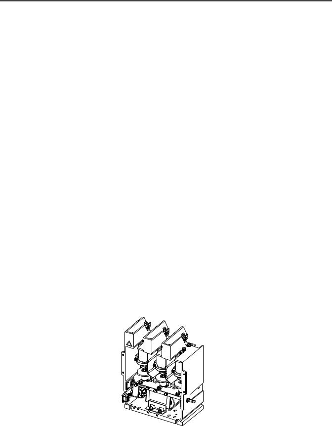
The Allen-Bradley, Bulletin 1502, 400 A vacuum contactors are designed for applications in the 2400 and 7200V range. The contactor is suitable for all types of AC loads, for example: three-phase motors, transformers, power capacitors and resistive heating loads.
The contactor uses three interrupters (hereafter referred to as vacuum bottles) operated by an electromagnet assembly through a mechanical linkage. They are resistant to adverse atmospheric conditions and provide long mechanical and electrical life.
The contactors are utilized in various starter and drive configurations, for example: full-voltage non-reversing, full-voltage reversing, two-speed, reduced voltage, synchronous, drive input/output and bypass applications. They are generally fixed mounted within the structures and the line and load terminations are made at the rear of the device. In most configurations, the main contactor is mechanically interlocked with the external operating handle and isolating switch.
Bulletin 1502 vacuum contactors are designed for use with the IntelliVAC and IntelliVAC Plus control module (refer to Publication 1503-UM053_-EN-P and 1503-UM054_-EN-P). The mechanical latch contactor may also be applied with an electromechanical (relay) control panel.
Bulletin 1502 electrically held and mechanical latch vacuum contactors are provided with coils rated for 108 VDC. The IntelliVAC and IntelliVAC Plus control module can accept a wide array of supply voltages for maximum flexibility (refer to Publication 1503-UM053_-EN-P and 1503-UM054_-EN-P).
Figure 1 - 400A Contactor
Rockwell Automation Publication 1502-UM052H-EN-P - June 2013 |
5 |
Chapter 1 Product Description
Vacuum Bottle Description |
Each vacuum bottle (Figure 2) consists of two contacts enclosed in a ceramic |
|
housing: an upper contact mounted to a fixed shaft, and a lower contact mounted |
|
to a movable shaft. A stainless steel bellows ensures the vacuum integrity of the |
|
bottle while letting the lower contact move towards and away from the fixed |
|
contact. |
|
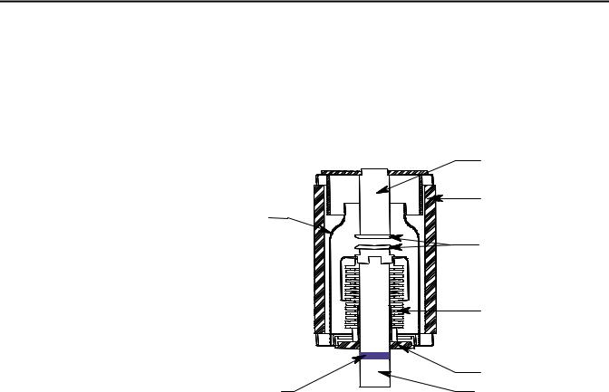
Figure 2 - Vacuum Bottle Cross Section |
Fixed shaft
Ceramic
Arc Shield
Contacts
Bellows
Contact Wear |
Bearing |
Indicator Line |
Movable Shaft |
Standard Electrically Held
Contactor Operation
Each vacuum bottle (Figure 2) consists of two contacts enclosed in a ceramic housing: an upper contact mounted to a fixed shaft, and a lower contact mounted to a movable shaft. A stainless steel bellows ensures the vacuum integrity of the bottle while letting the lower contact move towards and away from the fixed contact.
The standard electrically held contactor consists of three vacuum bottles. An electro-magnet assembly and a mechanical linkage are used to close the contacts.
•When the IntelliVAC or IntelliVAC Plus control module receives a close command, the contactor coils (two connected in series) are energized, and the current creates an electromagnet with the coils.
•The electromagnet pulls the armature plate towards the coils’ core, rotating the shaft and causing the actuator plate to move upwards.
•As the actuator plate moves, it pushes the insulator and movable shaft up, closing the contacts in the vacuum bottle.
•The IntelliVAC or IntelliVAC Plus control module supplies the current required to close the coils for 200 milliseconds. Afterward, the coil current is reduced to a lower hold-in value.
•When the IntelliVAC or IntelliVAC Plus control module has the close command removed, the coils are de-energized, opening the contactor.
6 |
Rockwell Automation Publication 1502-UM052H-EN-P - June 2013 |
Product Description |
Chapter 1 |
|
|
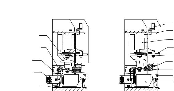
Insulator
Armature Plate & Shaft
Auxiliary Actuator
Control Wire Plug
Armature Stop Bracket
Figure 3 - Vacuum Contactor Operation
C.P.T. Fuse Clip |
Line Terminal |
Vacuum Bottle |
Load Terminal |
Flexible Bus |
Return Spring |
Actuator Plate |
Gap Adjustment Screw |
Magnet/Coil Assembly |
Contactor Open |
Contactor Closed |
Mechanically Latched
Contactor Operation
The mechanically latched contactor operates in much the same way as the electrically held (Figure 3) with only a few exceptions.
IntelliVAC and IntelliVAC Plus Control
•Once the contactor is closed, a spring-loaded mechanism moves a roller against the armature plate to hold it against the electromagnetic core.
•The contactor can be opened electrically by energizing a trip coil (via IntelliVAC or IntelliVAC Plus ‘open’ [TCO] output) which pulls the latch away from the armature, or by a push button mounted on the power cell door that mechanically releases the contactor.
Electromechanical Control
•When the control circuit is energized, the current creates an electromagnet in the closing coil.
•The electromagnet pulls the armature plate towards the coils’ core, rotating the shaft and causing the actuator plate to move upwards.
•As the actuator plate moves, it pushes the insulator and movable shaft up, closing the contacts in the vacuum bottle.
•Once the contactor is closed, a spring-loaded mechanism moves a roller against the armature plate to hold it against the electromagnetic core.
•The control circuit economizing auxiliary contact, on the left side of the contactor, changes from the normally closed state to the normally open state as the contactor closes. This de-energizes the relay that controls the closing coils.
Rockwell Automation Publication 1502-UM052H-EN-P - June 2013 |
7 |
Chapter 1 Product Description
•The contactor can be opened electrically by energizing a trip coil which pulls the latch away from the armature, or by a push button mounted on the power cell door that mechanically releases the contactor.
Note: The standard mechanical latch contactor requires external 120V AC (or DC) control relays and rectification circuit to control the standard DC closing and trip coils on the contactor (when IntelliVAC or IntelliVAC Plus is not used).
Contactor Identification
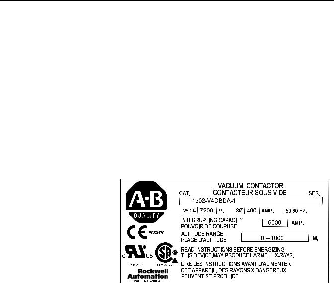
Each contactor is identified with a rating label (Figure 4) attached to the armature plate at the front of the contactor. The rating label information includes the Catalog Number (Cat.) Series Letter (Ser.) Voltage Rating, NonEnclosed Current Rating, Interrupting Capacity, Altitude Range (in meters), CSA, UL and CE markings.
Figure 4 - Contactor Rating Label (400A)
8 |
Rockwell Automation Publication 1502-UM052H-EN-P - June 2013 |

Product Description |
Chapter 1 |
|
|
Contactor Catalog Number
Explanation
The following catalog number explanation is used to identify the contactor and should be used when contacting your local Rockwell Automation Sales office, or the factory, for assistance.
Figure 5 - Contactor Catalog Number Explanation
1502 - |
|
|
V |
4 |
|
|
|
D |
|
B |
|
D |
|
A |
- |
|
1 |
|
||||||||||||||||
|
|
|
|
|
|
|
|
|
|
|
|
|
|
|
|
|
|
|
|
|
|
|
|
|
|
|
|
|
|
|
|
|
|
|
|
First |
|
Second |
|
|
Third |
|
|
Fourth |
|
|
Fifth |
|
|
Sixth |
|
Seventh |
|
|
Eighth |
||||||||||||||
|
Position |
|
Position |
|
Position |
|
Position |
|
Position |
|
Position |
|
Position |
|
|
Position |
||||||||||||||||||
|
|
|
|
|
|
|
|
|
|
|
|
|
|
|
|
|
|
|
|
|
|
|
|
|
|
|
|
|
|
|
|
|
|
|
|
Bulletin |
|
Contactor Type |
|
Contactor |
|
|
Nominal |
|
Fuse Mounting |
|
|
Coil |
|
|
Function |
|
|
Altitude |
|||||||||||||||
|
Number |
|
and Interlock |
|
|
Size |
|
Line Voltage |
|
Provisions |
|
|
Voltage |
|
|
|
|
|
Code (meters) |
|||||||||||||||
1502 |
|
|
|
V = Vacuum, |
|
4 = 400 A |
|
D = 7200 V |
|
B = 5000 V |
|
D = 110 V DC |
|
|
Refer to |
|
0 |
= -1000 – 5000 |
||||||||||||||||
|
|
|
|
|
|
VC = Vacuum, |
|
|
|
|
|
|
|
|
|
|
C = 7200 V |
|
E = 207 V DC |
|
TABLE 1 |
|
||||||||||||
|
|
|
|
|
|
|
|
|
|
|
|
|
|
|
|
|
|
|
1 |
= 0 – 1000 |
||||||||||||||
|
|
|
|
|
|
Optimized for |
|
|
|
|
|
|
|
|
|
|
|
|
|
|
|
|
|
|
|
|
|
|
||||||
|
|
|
|
|
|
|
|
|
|
|
|
|
|
|
|
|
|
|
|
|
|
|
|
|
|
|
|
2 |
= 1001–2000 |
|||||
|
|
|
|
|
|
IntelliVAC control |
|
|
|
|
|
|
|
|
|
|
|
|
|
|
|
|
|
|
|
|
|
|
3 |
= 2001–3000 |
||||
|
|
|
|
|
|
|
|
|
|
|
|
|
|
|
|
|
|
|
|
|
|
|
|
|
|
|
|
|
|
|
4 |
= 3001–4000 |
||
|
|
|
|
|
|
|
|
|
|
|
|
|
|
|
|
|
|
|
|
|
|
|
|
|
|
|
|
|
|
|
5 |
= 4001–5000 |
||
|
|
|
|
|
|
|
|
|
|
|
|
|
|
|
|
|
|
|
|
|
|
|
|
|
|
|
|
|
|
|
|
|
|
|
Table 1 - Vacuum Contactor Function
A |
3 pole, electrically held contactor |
|
|
B |
3 pole, mechanically latched contactor with electrical and mechanical release |
|
|
C |
3 pole, electrically held contactor with fast drop-out |
|
|
Rockwell Automation Publication 1502-UM052H-EN-P - June 2013 |
9 |

Chapter 1 Product Description
Contactor Specifications
Table 2 - Bulletin 1502 Medium Voltage 400 Amp Contactor Ratings
Voltage Ratings(1)
Maximum Rated Voltage |
|
|
|
|
7200 |
||
|
|
|
|
|
|
|
|
System Voltages |
|
|
|
|
|
2400, 3300, 4160 |
|
|
|
|
|
|
|
|
4800, 6600, 6900 |
|
|
|
|
||||
Dielectric Voltage Withstand Rating |
|
For 60 seconds (kV) |
18.2 / 20 (IEC) |
||||
|
|
|
|
||||
Basic Impulse Level (B.I.L.) Withstand |
|
Phase to Ground, Phase to Phase (kV) |
60 |
||||
|
|
|
|
|
|
|
|
Frequency Ratings |
|
|
|
|
Hertz |
50/60 |
|
|
|
|
|
|
|
|
|
Current Ratings(1) |
|
|
|
|
|
|
|
Rated Continuous Current (Amps) |
|
|
|
400 |
|||
|
|
|
|
||||
Maximum Interrupting Current Rating |
|
2400 V (RMS Sym Amps) |
6300 |
||||
|
|
|
|
|
|
|
|
|
|
|
|
|
|
5000 V (RMS Sym Amps) |
6300 |
|
|
|
|
|
|
|
|
|
|
|
|
|
|
7200 V (RMS Sym Amps) (2) |
6000 |
Maximum Interrupting MVA Rating |
|
2400 V (Sym MVA) |
25 |
||||
|
|
|
|
|
|
|
|
|
|
|
|
|
|
5000 V (Sym MVA) |
50 |
|
|
|
|
|
|
|
|
|
|
|
|
|
|
7200 V (Sym MVA)(2) |
75 |
Short-Circuit Withstand at Rated Voltage |
|
Current Peak ½ cycle (kA) |
60 |
||||
|
|
|
|
||||
Short Time Current Rating Capability |
|
For 1 second (kA) |
6.0 |
||||
|
|
|
|
|
|
|
|
|
|
|
|
|
|
For 30 seconds (kA) |
2.4 |
|
|
|
|
||||
Chop Current (Average RMS Amps) |
|
|
0.5 |
||||
|
|
||||||
Make and Break Capability at Rated Voltage (kA) |
4.0 |
||||||
|
|
|
|
|
|
|
|
Ambient Temperature |
|
|
|
|
°C |
40 |
|
|
|
|
|
|
|
|
|
Contactor Coil Data |
|
|
|
|
|
|
|
|
|
|
|
|
|||
Control Voltage |
|
Coil Voltage (VCL) |
|
|
|
||
(VCTL) |
|
|
|
|
|
|
|
|
|
|
|
|
Electro-Mechanical (Relay) Control (Mechanical Latch Only) |
||
|
|
|
|
|
|
||
120 VAC |
|
110 VDC |
|
|
Close Current (ADC) |
5.6 |
|
|
|
|
|
|
|
Trip Current (ADC) |
6.0 |
|
|
|
|
|
|
Pick-up Voltage |
102 |
|
|
|
|
|
|
|
|
|
|
|
|
|
|
Trip Voltage |
84 |
|
|
|
|
|
|
|
|
|
|
|
|
IntelliVAC and IntelliVAC Plus Control (Electrically Held & Mechanical Latch) |
|||
|
|
|
|
|
|
||
110 to 240 VAC |
|
VAC: |
|
|
Close Current (ADC, 200 milliseconds) |
4.3 |
|
or |
|
V |
= 2 |
X V |
|
|
|
|
|
|
|
||||
110 to 250 VDC (3) |
|
CL |
CTL |
|
Hold Current (ADC) |
0.48 |
|
|
(Max.) |
|
|
||||
|
|
VDC: |
|
|
Pick-up Voltage(3) |
95 |
|
|
|
|
|
Drop-out Voltage(3) |
75 |
||
|
|
VCL = VCTL |
|
|
|||
|
|
|
|
|
|
Trip Current (ADC, 200 milliseconds) |
5.5 |
|
|
|
|
|
|
Trip Voltage(3) |
70 |
10 |
Rockwell Automation Publication 1502-UM052H-EN-P - June 2013 |
Product Description |
Chapter 1 |
|
|
Table 2 - Bulletin 1502 Medium Voltage 400 Amp Contactor Ratings (Continued)
Operational Characteristics
Mechanical Life (Operations) x 1000 (4) |
|
Electrically Held |
2500 |
|
|
Mechanical Latch |
100 |
|
|
|
|
Electrical Life (Operations) x 1000(4) |
|
|
1000 |
Switching Frequency (Operations per hour) |
|
Electrically Held |
600 |
|
|
|
|
|
|
Mechanical Latch |
150 |
|
|
|
|
Opening and Closing Times |
|
|
|
|
|
||
|
Electro-Mechanical (Relay) Control (Mechanical Latch Only) |
||
|
|
|
|
Maximum Closing Time (120 VAC) |
|
50 or 60 Hz (milliseconds) |
160 |
|
|
|
|
Maximum Opening Time (120 VAC) |
|
50 or 60 Hz (milliseconds) |
50 |
|
|
|
|
IntelliVAC and IntelliVAC Plus Control (Electrically Held & Mechanical Latch) |
|||
|
|
|
|
Maximum Closing Time (50 to 60 Hz) |
|
120 / 240 VAC (milliseconds) |
100 / 70 |
|
|
|
|
Maximum Opening Time |
|
120 to 240 VAC (milliseconds) |
60 |
(without delay, for 50 to 60 Hz)(5) |
|
|
|
Capacitor Switching (max. KVAR) |
|
|
|
|
|
|
|
System Voltage |
|
2400V |
800 |
|
|
|
|
|
|
4160V |
1400 |
|
|
|
|
|
|
6900V |
2000 |
|
|
|
|
General |
|
|
|
|
|
||
Standard Altitude Capability (meters / feet)(1)(6) |
-1000...5000 / 3300...16,500 |
||
Contactor Weight (kg / lbs) |
|
|
21.8 / 48 |
|
|
|
|
Auxiliary Contact Rating |
|
|
A600 |
|
|
||
Auxiliary Contacts on the Vacuum Contactor (Max.)(7) |
3 N.O. / 3 N.C. |
||
(1)The voltage and current ratings listed are valid up to 1,000 m (3,300 ft). Please refer to Table 3 for ratings above this altitude.
(2)The IEC rating at 7200V (RMS Sym.) is 5300 A / 66 MVA.
(3)Control voltage, as measured at the input of the IntelliVAC or IntelliVAC Plus control module.
(4)Provided that regular maintenance is performed, as detailed in this manual.
(5)A contactor drop-out delay may be configured with the IntelliVAC or IntelliVAC Plus control module (refer to publications 1503-UM053_-EN-P and 1503-UM054_- EN-P).
(6)The full Altitude range is available with the IntelliVAC or IntelliVAC Plus control module only, and the IntelliVAC or IntelliVAC Plus is to be configured accordingly (refer to publications 1503-UM053_-EN-P and 1503-UM054_-EN-P). The standard mechanical latch contactors, if used with electro-mechanical control, are designed for -1000...1000 m (-3300...3300 ft). Higher altitudes are possible by changing the contactor return springs (refer to Figure 5 for suitable catalog numbers).
(7)The number of contactor auxiliary contacts depends on the contactor type. Some of the contacts are used in the typical control schemes used.
Rockwell Automation Publication 1502-UM052H-EN-P - June 2013 |
11 |

Chapter 1 Product Description
Table 3 - Altitude Derating
Altitude Rating |
|
Reduce Max. Continuous Current Rating By: |
Reduce B.I.L. Withstand Rating by: |
||
|
|
|
|
|
|
|
|
|
400 A |
800 A |
|
|
|
|
|
||
0...1000 m (0 3300 ft)... |
– |
– |
– |
||
|
|
|
|
|
|
1001... |
2000 m (3301... |
6600 ft) |
10 A |
20 A |
6.0 kV |
|
|
|
|
|
|
2001... |
3000 m (6601... |
9900 ft) |
20 A |
40 A |
12.0 kV |
|
|
|
|
|
|
3001... |
4000 m (9901... |
13,200 ft) |
30 A |
60 A |
18.0 kV |
|
|
|
|
|
|
4001... |
5000 m (13,201... |
16,500 ft) |
40 A |
80 A |
24.0 kV |
|
|
|
|
|
|
Product Approvals
•UL347
•CSA22.2 No. 14 and T.I.L. D-21
•IEC60470
•CE Mark
12 |
Rockwell Automation Publication 1502-UM052H-EN-P - June 2013 |

Chapter 2
Receiving and Handling
Receiving
The contactors have been tested both mechanically and electrically before leaving the factory. Immediately upon receiving the contactor, remove the packing material and check the contactor for possible shipping damage. If damage is found, do not discard any of the packaging material and, if possible note the damage on the “Bill of Lading” before accepting the shipment. Report any damage immediately to the claims office of the common carrier. Provide a description of the damage and as much identification as possible.
Preliminary Inspection
Handling
Check for any cracks or breaks due to impact.
Push on armature plate to ensure mechanisms are in good working order.
Use a HiPot tester to ensure vacuum bottle integrity (refer to Vacuum Bottle Integrity Test on page 14).
The contactor weighs approximately 48 lb (21.8 kg) and it is possible for one person to safely handle the contactor for a short time. When transporting the contactor over longer distances or sustained lifting, a forklift should be considered.
When a forklift is used to handle the equipment, the following precautions should be taken:
•Keep the contactor in an upright position.
•Carefully balance the contactor on the forks.
•Use a safety strap to steady the contactor and avoid shifting or tipping.
•Avoid excessive speeds and sudden starts, stops and turns.
•Never lift a contactor above an area where personnel are located.
Rockwell Automation Publication 1502-UM052H-EN-P - June 2013 |
13 |
Chapter 2 Receiving and Handling
Pre-Energization Inspection Before placing the contactor in service, inspect it carefully for possible damage sustained in transit or maintenance:
•Check housing for any cracks or breaks due to impact.
•Push on the armature plate and rotating shaft to ensure mechanism is in good working order.
•Inspect the contactor for dirt, stray or loose hardware, tools or metal chips. Vacuum clean if necessary.
Storage
Vacuum Bottle Integrity Test
If it is necessary to store the contactor before it is put into service, be certain to store it in a clean, dry area, free from dust and condensation. Do not store contactor outdoors.
Storage temperature should be maintained between -20...65 °C (-4...149 °F). If storage temperature fluctuates or if humidity exceeds 85%, space heaters should be used to prevent condensation.
The internal dielectric condition and vacuum integrity of the vacuum bottles is determined by this test.
ATTENTION: Do not apply a voltage higher than 25,000V across the open contacts of a vacuum bottle. Dangerous x-ray emissions may be produced.
ATTENTION: Vacuum bottles are thoroughly tested at the factory; however, mishandling during shipment may cause damage. It is very important to perform the vacuum bottle integrity test before energizing the contactor for the first time, and before it is returned to service after maintenance or repair; test may result in personal injury or damage to the equipment if the vacuum bottle integrity fails.
ATTENTION: High voltage testing is potentially hazardous. Use caution when performing the Hi-pot test. Failure to do so may result in sever burns, injury or death.
High-potential test instruments can be purchased to perform the vacuum bottle integrity test. A Megger cannot be used to measure vacuum integrity because the voltage is too low. One of the following AC Hi-pot testers is recommended as a test instrument.
MANUFACTURER |
ADDRESS |
|
|
Mitsubishi Type VI #4U17 |
Chicago, Ill., USA |
|
|
Jennings Model JHP-70A |
San Jose, CA., USA |
|
|
Hipotronics Model 7BT 60A |
Brewster, NY, USA |
|
|
14 |
Rockwell Automation Publication 1502-UM052H-EN-P - June 2013 |
Receiving and Handling |
Chapter 2 |
|
|
1.Clean the outside of the vacuum bottles with a non-linting cloth or industrial wipe before performing the test.
2.The contactor may be tested while it is in the power cell. The line connection of the contactor must be disconnected and the ground lead from the Hi-pot tester must be connected to the load side of the contactor. Any fuses in the top of the contactor must be removed.
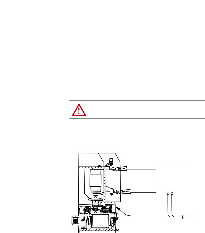
3.With the contactor in the open position, connect the test leads to the contactor power terminals as shown in Figure 6. It is recommended that an AC Hi-pot tester be used. Apply 16 kV for 60 seconds and monitor the leakage current. It should not exceed 5 mA. Test each vacuum bottle individually.
4.If no breakdown occurs, the vacuum bottle is in an acceptable condition. If a breakdown occurs, repeat the test once more. If the vacuum bottle fails a second time, it must be replaced. If no breakdown occurs in the second test, the vacuum bottle is in an acceptable condition.
ATTENTION: If one vacuum bottle fails, Rockwell Automation recommends the replacement of all three vacuum bottles, if the unit has been in service.
5.After the high potential voltage is removed from the vacuum bottles, the metal end caps of the vacuum bottles should be discharged with a grounding rod to remove any residual electrical charge.
Figure 6 - Vacuum Bottle Integrity Test Circuit
Vacuum
Checker
Vacuum Contactor in open position
The allowable leakage current value of 5 mA is exclusive of leakage due to test equipment leads. The test setup leakage can be determined by running the dielectric test with test leads not connected to the contactor and noting the maximum leakage current. If this value is more than 2 mA, it should be added to the 5 mA limit when testing the vacuum bottles.
Rockwell Automation Publication 1502-UM052H-EN-P - June 2013 |
15 |

Chapter 2 Receiving and Handling
Note: Rockwell Automation does not recommend DC Hi-pot testing because the values obtained during the test may not be a reliable indication of vacuum bottle integrity. Some specific DC “GO-NO GO” testers may provide suitable “defective” readings.
DC Hi-pot testing is unreliable because of a phenomenon known as Cathode Ray Tube Effect. This occurs when one contact of the vacuum bottle has a deformity, such as a burr or deposit, while the other contact remains flat and true. This sets up leakage currents which flow from a small surface to a large surface in one direction and vice versa when the polarity of the tester is changed. The resultant current is large in one direction which would incorrectly indicate a faulty vacuum bottle.
At best, DC testing will verify on some degree of vacuum integrity. It will not give any indication of the degree of vacuum since the contact surface can change with each operation of the vacuum contactor. AC testing, on the other hand, will provide reliable vacuum integrity indication. As well, the degree of vacuum within the bottle can be determined by comparing initial test results to the present readings. Increases in leakage current indicate a reduction in vacuum within the vacuum bottle.
For these reasons, Rockwell Automation recommends AC testing as the best and most reliable method of testing vacuum bottles.
A suitable GO-NO GO DC test unit is:
Manufacturer |
Address |
|
|
Programma, Model VIDAR |
Santa Rosa, CA, USA |
|
|
Insulation Resistance Test |
Use a 1000V Megger to verify that the resistance from phase-to-phase or phase- |
|
to-ground is greater than 500 megohms. |
16 |
Rockwell Automation Publication 1502-UM052H-EN-P - June 2013 |
Chapter 3
Installation
Mounting
The electrically held and the mechanically latched contactors are fixed mounted (bolted down) in the controller’s cabinet. Two retaining tabs at the rear of the contactor’s molded base can be used for mounting. The two mounting slots at the front of the contactor’s molded base are used to secure the contactor with
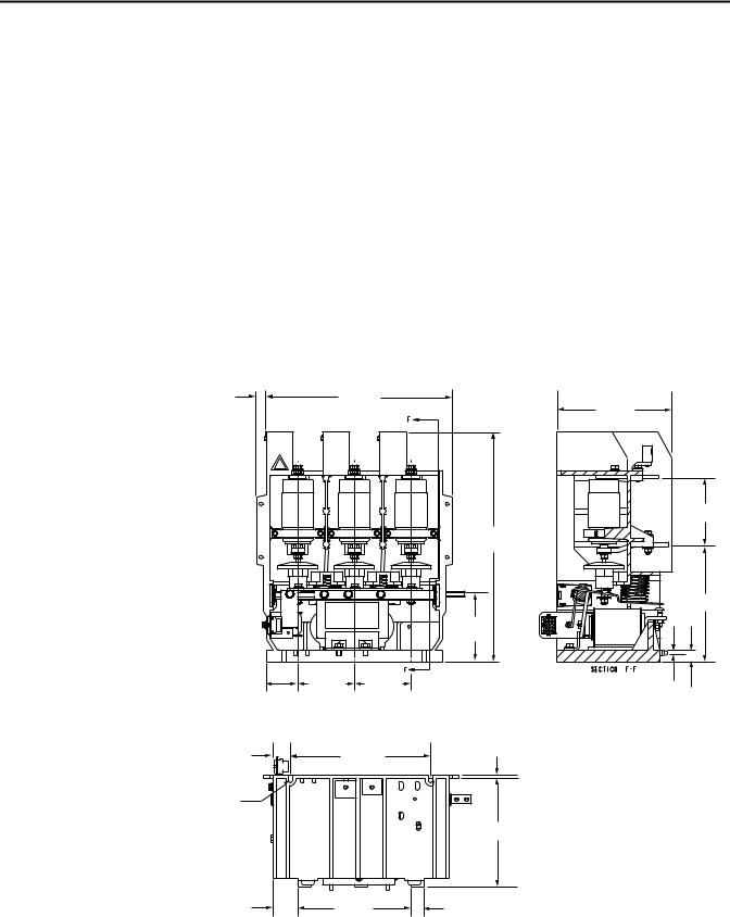
1/4 in. bolts. The appropriate mounting configurationisprovidedinsidethepowercells of Allen-Bradley controllers. If the contactor is supplied as an OEM component for installation in a custom application, refer to the dimensional information in Figure 7. If the contactor is to be mounted in an enclosure designed by an OEM, make sure there is a minimum of 3 in. (76 mm) of air space between live parts (terminals and vacuum bottles) and any part of the enclosure.
Figure 7 - Contactor Mounting Details
0.75 [19] |
13.22 [336] |
|
|
|
17.24 |
|
|
[438] |
|
|
5.00 |
|
|
[127] |
|
3.15 [80] |
4.25 [108] |
|
4.25 [108] |
|
Front View
1.36 |
[35] |
10.50 [267] |
0.37 [9] |
|
|||
0.281 [7] |
|
|
|
wide slots |
|
|
|
|
|
|
7.87 [200] |
2.12 [54] |
8.00 [203] |
0.98 [25] |
|
8.64 [219] |
4.96 [126] |
8.53 [217] |
0.37 [9] 0.91
[23]
Cut-away View
Bottom View
Rockwell Automation Publication 1502-UM052H-EN-P - June 2013 |
17 |
Chapter 3 |
Installation |
|
|
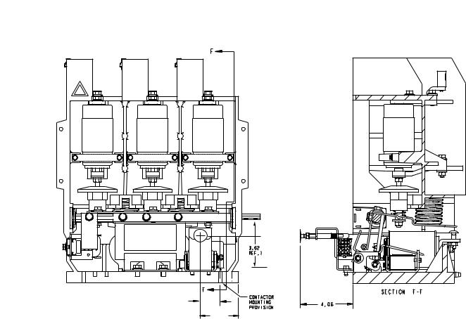
Figure 8 - Mechanical Latch Dimensions (Optional)
1 . 5 3 |
2 . 9 3 |
Electrical Connections
A wire harness connects the control wiring to the contactor from the low voltage control panel. The harness connects to a wire plug on the lower left side of the contactor. If the contactor is supplied as an OEM component for installation in a custom application, the following two control options and a connecting wire harness are available from Rockwell Automation.
•IntelliVAC and IntelliVAC Plus control modules
•Electromechanical control panel (for latch contactors only)
Connect incoming power to the line side terminals at the top, rear of the contactor near the control fuse clips. Use 3/8 in. (10 mm) bolts torqued to 20 lb•ft (292 N•m) to secure the connection.
Connect outgoing power to the load side terminals halfway down the rear of the contactor. Use 3/8 in. (10 mm) bolts torqued to 20 lb•ft (292 N•m) to secure the connection.
For mechanically latched contactors, ensure the manual trip button in the cabinet door is in line with the trip lever on the contactor.
18 |
Rockwell Automation Publication 1502-UM052H-EN-P - June 2013 |
Loading...