


1734-IT2I
Table of contents
 Loading...
POINT I/O Thermocouple and RTD
Modules
Catalog Numbers 1734-IR2, 1734-IR2E and 1734-IT2I
User Manual
2
WARNING
IMPORTANT
ATTENTION
SHOCK HAZARD
BURN HAZARD
Important User Information
Solid state equipment has operational characteristics differing from those of
electromechanical equipment. Safety Guidelines for the Application, Installation and
Maintenance of Solid State Controls (publication SGI-1.1
Automation sales office or online at http://literature.rockwellautomation.com
available from your local Rockwell
) describes
some important differences between solid state equipment and hard-wired
electromechanical devices. Because of this difference, and also because of the wide variety
of uses for solid state equipment, all persons responsible for applying this equipment must
satisfy themselves that each intended application of this equipment is acceptable.
In no event will Rockwell Automation, Inc. be responsible or liable for indirect or
consequential damages resulting from the use or application of this equipment.
The examples and diagrams in this manual are included solely for illustrative purposes.
Because of the many variables and requirements associated with any particular installation,
Rockwell Automation, Inc. cannot assume responsibility or liability for actual use based on
the examples and diagrams.
No patent liability is assumed by Rockwell Automation, Inc. with respect to use of
information, circuits, equipment, or software described in this manual.
Reproduction of the contents of this manual, in whole or in part, without written permission
of Rockwell Automation, Inc., is prohibited.
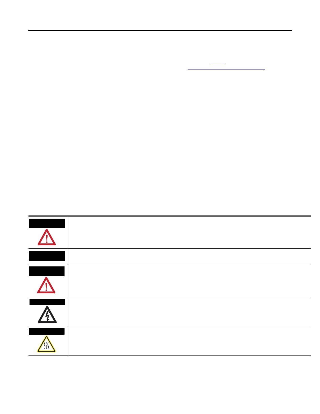
Throughout this manual, when necessary, we use notes to make you aware of safety
considerations.
Identifies information about practices or circumstances that can cause an explosion in a hazardous environment, which may
lead to personal injury or death, property damage, or economic loss.
Identifies information that is critical for successful application and understanding of the product.
Identifies information about practices or circumstances that can lead to: personal injury or death, property damage, or
economic loss. Attentions help you identify a hazard, avoid a hazard, and recognize the consequence.
Labels may be on or inside the equipment, such as a drive or motor, to alert people that dangerous voltage may be present.
Labels may be on or inside the equipment, such as a drive or motor, to alert people that surfaces may reach dangerous
temperatures.
Allen-Bradley, Rockwell Automation, POINT I/O, RSLinx, RSLogix 5000, and TechConnect are trademarks of Rockwell Automation, Inc.
Trademarks not belonging to Rockwell Automation are property of their respective companies.
Publication 1734-UM004F-EN-E - December 2012

Summary of Changes
About POINT I/O Modules
Table of Contents
Important User Information . . . . . . . . . . . . . . . . . . . . . . . . . . . . . . . . . . 2
New and Revised Information . . . . . . . . . . . . . . . . . . . . . . . . . . . . . 7
Change Bars . . . . . . . . . . . . . . . . . . . . . . . . . . . . . . . . . . . . . . . . . . . . 7
Preface
Who Should Use this Manual . . . . . . . . . . . . . . . . . . . . . . . . . . . . . . . . . 9
Purpose of this Manual . . . . . . . . . . . . . . . . . . . . . . . . . . . . . . . . . . . . . . 9
Related Documentation. . . . . . . . . . . . . . . . . . . . . . . . . . . . . . . . . . . 9
Common Techniques Used in this Manual. . . . . . . . . . . . . . . . . . . . . . 10
Chapter 1
Overview. . . . . . . . . . . . . . . . . . . . . . . . . . . . . . . . . . . . . . . . . . . . . . . . . 11
Module Features. . . . . . . . . . . . . . . . . . . . . . . . . . . . . . . . . . . . . . . . . . . 11
Selecting a Module Input Type . . . . . . . . . . . . . . . . . . . . . . . . . . . . . . . 12
Communicating with Your Module. . . . . . . . . . . . . . . . . . . . . . . . . . . . 12
Default Data Map for the Thermocouple Input Module
(catalog number 1734-IT2I) . . . . . . . . . . . . . . . . . . . . . . . . . . . . . . 13
Default Data Map for the RTD Input Module
(catalog numbers 1734-IR2, and 1734-IR2E). . . . . . . . . . . . . . . . . 13
Data Format (1734-IT2I, 1734-IR2, and 1734-IR2E modules) . . 14
Use Module Alarms . . . . . . . . . . . . . . . . . . . . . . . . . . . . . . . . . . . . . . . . 15
Overrange Alarm (1734-IT2I, 1734-IR2, and
1734-IR2E modules) . . . . . . . . . . . . . . . . . . . . . . . . . . . . . . . . . . . . 15
Underrange Alarm (1734-IT2I, 1734-IR2, and
1734-IR2E modules) . . . . . . . . . . . . . . . . . . . . . . . . . . . . . . . . . . . . 15
Level Alarms (1734-IT2I, 1734-IR2, and
1734-IR2E modules) . . . . . . . . . . . . . . . . . . . . . . . . . . . . . . . . . . . . 15
Open-wire Alarm (1734-IT2I, 1734-IR2, and
1734-IR2E modules) . . . . . . . . . . . . . . . . . . . . . . . . . . . . . . . . . . . . 16
Cold Junction Compensation (1734-IT2I module) . . . . . . . . . . . . . . . 16
Chapter Summary. . . . . . . . . . . . . . . . . . . . . . . . . . . . . . . . . . . . . . . . . . 16
Chapter 2
Install the Module
Overview. . . . . . . . . . . . . . . . . . . . . . . . . . . . . . . . . . . . . . . . . . . . . . . . . 17
Preventing Electrostatic Discharge. . . . . . . . . . . . . . . . . . . . . . . . . 17
Environment and Enclosure . . . . . . . . . . . . . . . . . . . . . . . . . . . . . . 18
Install the Mounting Base . . . . . . . . . . . . . . . . . . . . . . . . . . . . . . . . . . . 18
Install an I/O Module . . . . . . . . . . . . . . . . . . . . . . . . . . . . . . . . . . . . . . 20
Install the Removable Terminal Block . . . . . . . . . . . . . . . . . . . . . . . . . 21
Remove a Mounting Base . . . . . . . . . . . . . . . . . . . . . . . . . . . . . . . . . . . 22
Wire the Modules . . . . . . . . . . . . . . . . . . . . . . . . . . . . . . . . . . . . . . . . . . 23
Chapter Summary. . . . . . . . . . . . . . . . . . . . . . . . . . . . . . . . . . . . . . . . . . 24
Chapter 3
Configure Your Module
iii Publication 1734-UM004F-EN-E - December 2012
Overview. . . . . . . . . . . . . . . . . . . . . . . . . . . . . . . . . . . . . . . . . . . . . . . . . 25
Configuration Overview . . . . . . . . . . . . . . . . . . . . . . . . . . . . . . . . . . . . 25
Commissioning a Node . . . . . . . . . . . . . . . . . . . . . . . . . . . . . . . . . . . . . 25

iv Table of Contents
Using the RSNetWorx Commissioning Tool. . . . . . . . . . . . . . . . . 26
Use Sequential Auto Addressing. . . . . . . . . . . . . . . . . . . . . . . . . . . 27
Use Third Party Configuration Software . . . . . . . . . . . . . . . . . . . . 27
Add the Adapter to Your Network. . . . . . . . . . . . . . . . . . . . . . . . . . . . 27
Add I/O Modules to Your Network POINTBus. . . . . . . . . . . . . 28
Set the Thermocouple Input Module Parameters Using RSNetWorx 30
Configure Your Thermocouple Input Module. . . . . . . . . . . . . . . . . . . 32
Basic Set-up Parameters . . . . . . . . . . . . . . . . . . . . . . . . . . . . . . . . . 32
Advanced Setup Parameters . . . . . . . . . . . . . . . . . . . . . . . . . . . . . . 33
Basic Setup . . . . . . . . . . . . . . . . . . . . . . . . . . . . . . . . . . . . . . . . . . . 35
Advanced Setup. . . . . . . . . . . . . . . . . . . . . . . . . . . . . . . . . . . . . . . . 36
Set the RTD Input Module Parameters Using RSNetWorx . . . . . . . . 37
Configure Your RTD Input Module . . . . . . . . . . . . . . . . . . . . . . . . . . 39
Basic Setup Parameters . . . . . . . . . . . . . . . . . . . . . . . . . . . . . . . . . . 39
Advanced Setup Parameters . . . . . . . . . . . . . . . . . . . . . . . . . . . . . . 40
Basic Setup. . . . . . . . . . . . . . . . . . . . . . . . . . . . . . . . . . . . . . . . . . . . 42
Advanced Setup. . . . . . . . . . . . . . . . . . . . . . . . . . . . . . . . . . . . . . . . 43
Check I/O Status and View the EDS File . . . . . . . . . . . . . . . . . . . . . . 44
1734-IT2I module . . . . . . . . . . . . . . . . . . . . . . . . . . . . . . . . . . . . . . 44
1734-IR2 and 1734-IR2E modules. . . . . . . . . . . . . . . . . . . . . . . . . 45
Chapter Summary . . . . . . . . . . . . . . . . . . . . . . . . . . . . . . . . . . . . . . . . . 46
Calibrate Your Module
Troubleshoot the Module
Configure Modules in
RSLogix 5000 Software
Chapter 4
Overview . . . . . . . . . . . . . . . . . . . . . . . . . . . . . . . . . . . . . . . . . . . . . . . . 47
When and How to Calibrate Your Module . . . . . . . . . . . . . . . . . . . . . 47
Calibration Method . . . . . . . . . . . . . . . . . . . . . . . . . . . . . . . . . . . . . . . . 47
Tools and Equipment Required to Calibrate
Your Thermocouple Module. . . . . . . . . . . . . . . . . . . . . . . . . . . . . . . . . 47
Calibrate the Thermocouple Input Module . . . . . . . . . . . . . . . . . . . . . 48
Access Calibration Parameters in RSNetWorx . . . . . . . . . . . . . . . 49
Input (mV) Calibration . . . . . . . . . . . . . . . . . . . . . . . . . . . . . . . . . . . . . 50
Cold Junction Compensation Calibration . . . . . . . . . . . . . . . . . . . 53
Tools and Equipment Required to Calibrate
Your RTD Module . . . . . . . . . . . . . . . . . . . . . . . . . . . . . . . . . . . . . . . . 56
Calibrate the RTD Input Module . . . . . . . . . . . . . . . . . . . . . . . . . . . . . 56
Chapter Summary . . . . . . . . . . . . . . . . . . . . . . . . . . . . . . . . . . . . . . . . . 60
Chapter 5
Overview . . . . . . . . . . . . . . . . . . . . . . . . . . . . . . . . . . . . . . . . . . . . . . . . 61
Interpret the Status Indicators. . . . . . . . . . . . . . . . . . . . . . . . . . . . . . . . 61
Chapter Summary . . . . . . . . . . . . . . . . . . . . . . . . . . . . . . . . . . . . . . . . . 62
Appendix A
Overview . . . . . . . . . . . . . . . . . . . . . . . . . . . . . . . . . . . . . . . . . . . . . . . . 63
Publication 1734-UM004F-EN-E - December 2012

Calculate Absolute Accuracy and
Accuracy Drift
Index
Table of Contents v
Understanding Data, Connection, and
Communication Formats. . . . . . . . . . . . . . . . . . . . . . . . . . . . . . . . . . . . 63
Configure Your Module. . . . . . . . . . . . . . . . . . . . . . . . . . . . . . . . . . . . . 64
Use the Help Button . . . . . . . . . . . . . . . . . . . . . . . . . . . . . . . . . . . . . . . 65
Working with Dialogs . . . . . . . . . . . . . . . . . . . . . . . . . . . . . . . . . . . . . . 65
Work with Dialogs for RTD Modules . . . . . . . . . . . . . . . . . . . . . . 65
Work with Dialogs for Thermocouple Modules . . . . . . . . . . . . . . 70
Appendix B
Overview. . . . . . . . . . . . . . . . . . . . . . . . . . . . . . . . . . . . . . . . . . . . . . . . . 77
Calculate with Formulas. . . . . . . . . . . . . . . . . . . . . . . . . . . . . . . . . . . . . 77
Absolute Accuracy Formula . . . . . . . . . . . . . . . . . . . . . . . . . . . . . . 77
Accuracy Drift Formula. . . . . . . . . . . . . . . . . . . . . . . . . . . . . . . . . . 77
Publication 1734-UM004F-EN-E - December 2012

vi Table of Contents
Notes:
Publication 1734-UM004F-EN-E - December 2012

Summary of Changes
This publication contains new and revised information not in the last release.
New and Revised Information
See the table for a summary of the major changes in this manual.
Revised to include Chapter
New Appendix on Absolute Accuracy and Accuracy Drift calculation Appendix B
Change Bars
Change bars (as shown with this paragraph) show the areas in this manual that
differ from previous editions and indicate the addition of new or revised
information.
vii Publication 1734-UM004F-EN-E - December 2012

viii Summary of Changes
Notes:
Publication 1734-UM004F-EN-E - December 2012

Preface
Read this preface to familiarize yourself with the rest of the manual. It provides
information concerning:
• who should use this manual
• the purpose of this manual
• related documentation
• conventions used in this manual
Who Should Use this Manual
Purpose of this Manual
You must be able to use your selected configuration software to set up and
calibrate these modules. You must have the capability to download and use
files.
We assume you know how to do this in this manual. If you do not, refer to
your software user manuals or online help before attempting to use these
modules.
This manual describes how to install, configure and troubleshoot your
Thermocouple and Resistance Termperature Detector (RTD) modules.
For Information About See
About POINT I/O Modules Chapter 1
Install the Module Chapter 2
Configure Your Module Chapter 3
Calibrate Your Module Chapter 4
Troubleshoot the Module Chapter 5
Configure Modules in RSLogix 5000 Software Appendix A
Calculate Absolute Accuracy and Accuracy Drift Appendix B
Related Documentation
The following documents contain additional information concerning Rockwell
Automation products. To obtain a copy, contact your local
Rockwell Automation office or distributor.
Resource Description
POINT I/O RTD and Thermocouple Input Module
Installation Instructions, publication 1734-IN011
Analog Input Modules Installation Instructions,
publication 1734-IN024
ix Publication 1734-UM004F-EN-E - December 2012
Information about specification and safety approval concerning 1734-IT2I,
1734-IR2, and 1734-IR2E modules.
Information about how to install the 1734-IE2C, Series C, POINT I/O Current
Input Analog Module, 1734-IE2V, Series C, POINT I/O Voltage Input Analog
Module, and POINT I/O 2 Current and 2 Voltage Input Analog Module.
x
Resource Description
Analog Output Modules Installation Instructions,
publication 1734-IN002
Cold Junction Wiring Base Assembly Installation
Instruction, publication 1734-IN583
DeviceNet Communication Interface Installation
Instructions, publication 1734-IN057
Expansion Power Supply Installation Instructions,
publication 1734-IN058
Field Potential Distributor Installation Instructions,
publication 1734-IN059
POINT I/O Selection Guide, publication 1734-SG001
Protected Output Modules Installation Instructions,
publication 1734-IN056
Relay Output Modules Installation Instructions,
publication 1734-IN055
Sink Input Modules Installation Instructions, publication
1734-IN051
Source Output Modules Installation Instructions,
publication 1734-IN052
.
Information about how to install 1734-OE2C and 1734-OE2V, Series C Point I/O
Current and Voltage Output Analog Modules.
Information about how to install the POINT I/O Cold Junction Compensation
Wiring Base Assembly.
Information about how to install the 1734-PDN Series B POINT I/O DeviceNet
Communication Interface Module.
Information about how to installthe 1734-EP24DC, Series B POINT I/O 24V DC
Expansion Power Supply.
Information about how to install the 1734-FPD, Series B POINT I/O Field
Potential Distributor Module.
A description and overview of the 1734 and 1734D series POINT I/O modules
and compatible control platforms. Also includes an overview of how to specify
a POINT I/O system.
Information about how to install 1734-OB2E, -OB4E and -OB8E Series C POINT
I/O Protected Output Modules.
Information about how to install 1734-OW2 and 1734-OW4, Series C POINT I/O
2 or 4 Relay Output Modules.
Information about how to install 1734-IB2, 1734-IB4, 1734-IB8, Series C POINT
I/O Input Modules.
Information about how to install 1734-IV2, -IV4 and -IV8 Series C POINT I/O
Source Input Modules.
Very High Speed Counter Modules Installation
Instructions, publication 1734-IN003
Wiring Base Assembly Installation Instructions,
publication 1734-IN511
Wiring Base Assembly Installation Instructions,
publication 1734-IN013
Common Techniques Used in this Manual
Information about how to install 1734-VHSC5 and 1734-VHSC24, Series C
POINT I/O 5V DC and 24V DC Very High Speed Counter Modules.
Information about how to install 1734-TB and -TBS POINT I/O Wiring Base
Assemblies.
Information about how to install 1734-TB3 and -TB3S POINT I/O Wiring Base
Assemblies.
The following conventions are used throughout this manual:
• Bulleted lists such as this one provide information, not procedural steps.
• Numbered lists provide sequential steps or hierarchical information.
• Italic type is used for emphasis.
Publication 1734-UM004F-EN-E - December 2012

About POINT I/O Modules
Chapter
1
Overview
Module Features
Read this chapter to familiarize yourself with configurable features on the
1734-IT2I, 1734-IR2, and 1734-IR2E modules. The following table lists where
to find specific information in this chapter.
Topic Page
Module Features 1
Selecting a Module Input Type 2
Communicating with Your Module 2
Use Module Alarms 5
Cold Junction Compensation (1734-IT2I module) 6
Chapter Summary 6
The module features include:
Input type
•Sensor type
• Data formats
• Preset temperature selection
•Fault mode
• Overrange alarms
•Underrange alarms
• Fault alarms
You must use your programming software, like Rockwell Automation
RSNetWorx, to configure these features. See this chapter for a brief
description of each module feature. Use the online help included with your
programming software to perform specific configuration. You can find the
EDS files for this module at www.ab.com/networks/eds/.
1 Publication 1734-UM004F-EN-E - December 2012

2 About POINT I/O Modules
Selecting a Module Input Type
The 1734-IT2I module consists of two isolated millivolt inputs (+70 mV).
Configure the module to do the linearization necessary for thermocouple
inputs. See the table for a list of supported thermocouple input types.
Supported Sensor Types – Thermocouple
mV (default) -70...+70 mV
B 572...3272 °F (300...1800 °C)
C 32...4199 °F (0...2315 °C)
E -418...+1832 °F (-250...+1000 °C)
J -346...+2192 °F (-210...+1200 °C)
K -418...+2502 °F (-250...+1372 °C)
N -418...+2372 °F (-250...+1300 °C)
R 32...3214 °F (0...1768 °C)
S 32...3214 °F (0...1768 °C)
T -418...+752 °F (-250...+400 °C)
The 1734-IR2 consists of two RTD inputs (0...600 W). Configure the module
to do the linearization necessary for RTD inputs. See the table for a list of
supported input types.
Communicating with Your Module
Supportted Sensor Types – RTD
100 Pt α = 0.00385 Euro -328...1598 °F (-200...+870 °C)
200 Pt α = 0.00385 Euro -328...1166 °F (-200...+630 °C)
100 Pt α = 0.003916 U.S. -328...1166 °F (-200...+630 °C)
200 Pt α = 0.003916 U.S. -328...1166 °F (-200...+630 °C)
10 Cu α = 0.00427 -328...500 °F (-200...+260 °C)
100 Ni α = 0.00618 -76...+482 °F (-60...+250 °C)
120 Ni α = 0.00618 -76...+482 °F (-60...+250 °C)
120 Ni α = 0.00672 -76...+482 °F (-60...+250 °C)
The 1734-IR2E consists of two RTD inputs (0...200 W). Configure the module
to do the linearization necessary for RTD inputs. See the table for a list of
supported input types.
I/O messages are sent to (consumed) and received from (produced) the
POINT I/O modules. These messages are mapped into the processor’s
memory. The Thermocouple input module produces 8 bytes of input data
(scanner Rx) and fault status data. It does not consume I/O data (scanner Tx).
Publication 1734-UM004F-EN-E - December 2012
The RTD input module produces 6 bytes of input data (scanner Rx) and fault
status data. It does not consume I/O data (scanner Tx).
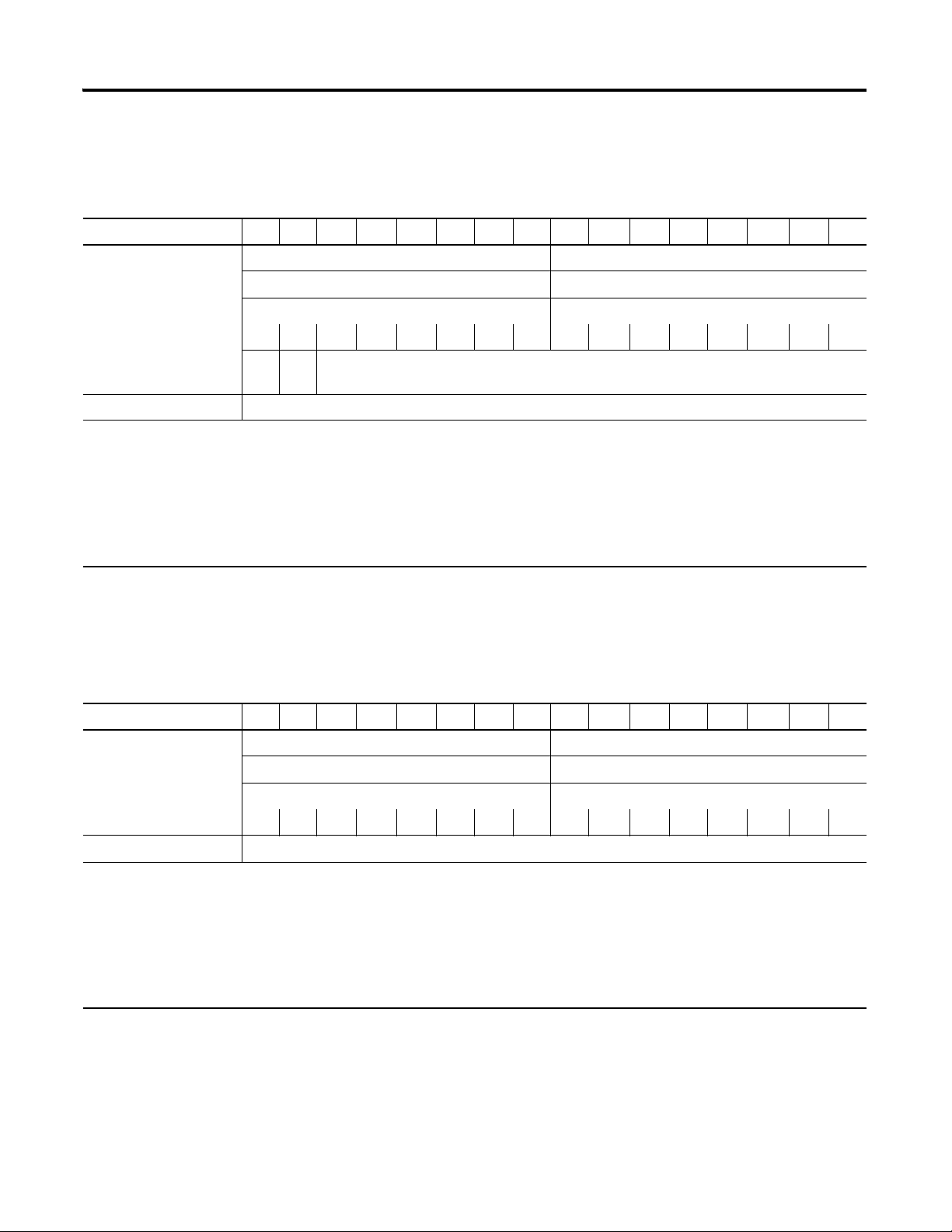
Default Data Map for the Thermocouple Input Module (catalog number 1734-IT2I)
15 14 13 12 11 10 09 08 07 06 05 04 03 02 01 00
Produces (scanner Rx) Input Channel 0 - High Byte Input Channel 0 - Low Byte
Input Channel 1 - High Byte Input Channel 1 - Low Byte
Status Byte for Channel 1 Status Byte for Channel 0
OR UR HHA LLA HA LA CM CF OR UR HHA LLA HA LA CM CF
OR UR Cold Junction Temperature
(Selectable: Channel 0, Channel 1, or Average of both Channel 0 and 1)
Consumes (scanner Tx) No consumed data
Where: OR = Overrange; 0 = no error, 1 = fault (value went above selected range)
UR = Underrange; 0 = no error, 1 = fault (value went below selected range)
HHA = High/High Alarm; 0 = no error, 1 = fault (value went below setpoint
LLA = Low/Low Alarm; 0 = no error, 1 = fault (value went below setpoint
HA = High Alarm; 0 = no error, 1 = fault (value went below setpoint
LA = Low Alarm; 0 = no error, 1 = fault (value went below setpoint)
CM = Calibration Mode; 0 = normal, 1 = calibration mode
CF = Channel Fault status; 0 = no error, 1 = fault
About POINT I/O Modules 3
Default Data Map for the RTD Input Module (catalog numbers 1734-IR2, and 1734-IR2E)
15 14 13 12 11 10 09 08 07 06 05 04 03 02 01 00
Produces (scanner Rx) Input Channel 0 - High Byte Input Channel 0 - Low Byte
Input Channel 1 - High Byte Input Channel 1 - Low Byte
Status Byte for Channel 1 Status Byte for Channel 0
OR UR HHA LLA HA LA CM CF OR UR HHA LLA HA LA CM CF
Consumes (scanner Tx) No consumed data
Where: OR = Overrange; 0 = no error, 1 = fault (value went above selected range)
UR = Underrange; 0 = no error, 1 = fault (value went below selected range)
HHA = High/High Alarm; 0 = no error, 1 = fault (value went below setpoint)
LLA = Low/Low Alarm; 0 = no error, 1 = fault (value went below setpoint)
HA = High Alarm; 0 = no error, 1 = fault (value went below setpoint)
LA = Low Alarm; 0 = no error, 1 = fault (value went below setpoint)
CM = Calibration Mode; 0 = normal, 1 = calibration mode
CF = Channel Fault status; 0 = no error, 1 = fault
Publication 1734-UM004F-EN-E - December 2012
4 About POINT I/O Modules
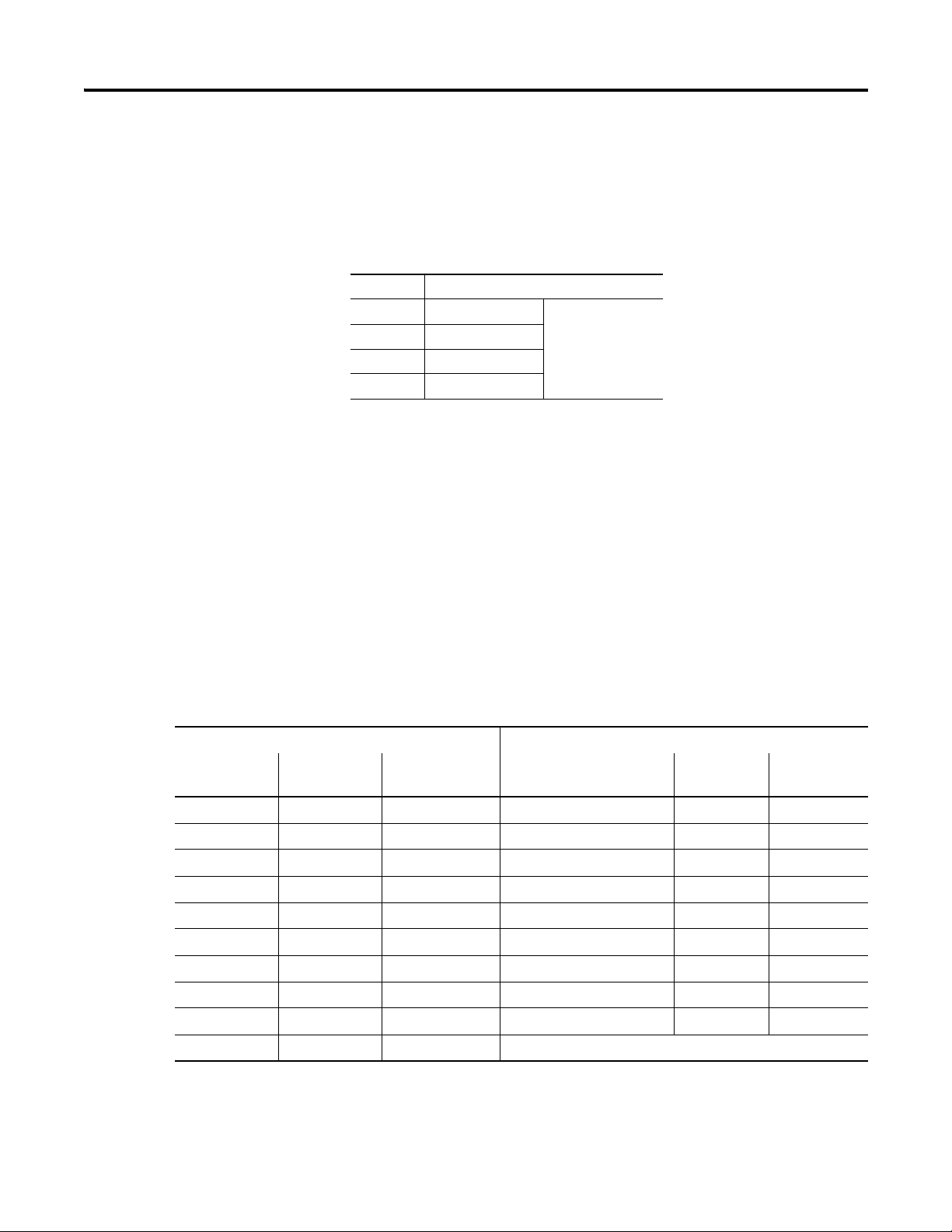
Data Format (1734-IT2I, 1734-IR2, and 1734-IR2E modules)
You must choose a module data format in your user program. Select the
format. These are four predefined scales and one custom scale.
Data Formats
mV Custom Scale
⋅ C Celsius Predefined Scale
⋅ F Fahrenheit
⋅ KKelvin
⋅ R Rankine
°C, F, °R, and °K returns data in tenths of a degree (250 implies 25.0 °).
For the 1734-IR2E,
(250 implies 2.50
⋅ C, ⋅ F, ⋅ R, and ⋅ K returns data in hundreths of a degree
⋅ ). If scaling is set to 10,000 and 20,000, the module returns
hundredths of an ohm (12345 implies 123.45).
For the 1734-IR2, if using ohms, the default data returned is in tenths of ohms
(1234 implies 123.4 Ω).
For the 1734-IT2, if using mV, the default data is returned in hundredths of a
mV, or tens of a μV (3500 implies 35.00
⋅ ).
If the input scale is custom scale, you can specify scaling points as shown in
the table.
1734-IT2I Thermocouple Input Module 1734-IR2 RTD Input Module
Thermocouple
Ty pe
mV 0 mV 70mV Ohms 100 Ω 500 Ω
Type B 212 °F (100 °C) 1832 °F (1000 °C) 100 Ω Ptα = 0.00385 Euro 32 °F (0 °C) 932 °F (500 °C)
Type C 32 °F (0 °C) 4199 °F (2315 °C) 200 Ω Ptα = 0.00385 Euro 32 °F (0 °C) 932 °F (500 °C)
Type E 32 °F (0 °C) 1832 °F (1000 °C) 100 Ω Ptα = 0.003916 U.S. 32 °F (0 °C) 932 °F (500 °C)
Type J 32 °F (0 °C) 1832 °F (1000 °C) 200 Ω Ptα = 0.003916 U.S. 32 °F (0 °C) 932 °F (500 °C)
Type K 32 °F (0 °C) 1832 °F (1000 °C) 10 Ω Cuα = 0.00427 32 °F (0 °C) 482 °F (250 °C)
Low Scaling
Endpoint
High Scaling
Endpoint
RTD Type Low Scaling
Endpoint
High Scaling
Endpoint
Type N 32 °F (0 °C) 1832 °F (1000 °C) 100 Ω Niα = 0.00618 32 °F (0 °C) 482 °F (250 °C)
Type R 32 °F (0 °C) 1832 °F (1000 °C) 120 Ω Niα = 0.00672 32 °F (0 °C) 482 °F (250 °C)
Type S 32 °F (0 °C) 1832 °F (1000 °C) 120 Ω Niα = 0.00618 32 °F (0 °C) 482 °F (250 °C)
Type T 32 °F (0 °C) 212 °F (100 °C)
Publication 1734-UM004F-EN-E - December 2012

1734-IR2E RTD Input Module
About POINT I/O Modules 5
Use Module Alarms
RTD Type Low Scaling
Endpoint
O hms 100 Ω 200 Ω
100 Ω Ptα = 0.00385 Euro 32 °F (0 °C) 572 °F (300 °C)
POINT I/O modules are capable of generating the following alarms.
•Overrange
•Underrange
• Level (low-low, low, high, high-high)
• Cold-junction Compensation (CJC) Fault (1734-IT2 only)
•Open-wire Detection
High Scaling
Endpoint
Overrange Alarm (1734-IT2I, 1734-IR2, and 1734-IR2E modules)
The channel overrange alarm is set if the input is greater than the maximum
temperature (thermocouple or RTD range dependent), millivolt (+75 mV) or
resistance (600 Ω) range value, or above the maximum range of the
thermocouple or RTD.
The cold junction compensator has its own overrange alarm. If the CJC
temperature goes above 70 ⋅ C, the overrange alarm is set.
Underrange Alarm (1734-IT2I, 1734-IR2, and 1734-IR2E modules)
The channel underrange alarm is set if the input is less than the minimum
temperature (thermocouple or RTD range dependent), millivolt (-75 mV) or
resistance (10 Ω) range value, or below the minimum range of the
thermocouple or RTD.
The cold junction compensator has its own underrange alarm. If the CJC
temperature goes below 0 ⋅ C, the underrange alarm is set.
Level Alarms (1734-IT2I, 1734-IR2, and 1734-IR2E modules)
The following level alarms are available.
•Low
Publication 1734-UM004F-EN-E - December 2012

6 About POINT I/O Modules
• Low-Low
•High
•High-High
When the channel input goes below a low alarm or above a high alarm, a bit is
set in the data table. All Alarm Status bits can be read individually or by
reading the Channel Status Byte (Bits 2...5 for channel 0; bits 10...13 for
channel 1).
You can configure each channel alarm individually.
Open-wire Alarm (1734-IT2I, 1734-IR2, and 1734-IR2E modules)
The module has the ability to check for a broken or detached wire. In any
mode, if a broken/detached lead is detected, the data value is forced to
maximum and the overrange alarm is set. Once the alarm is issued, it remains
active as long as the input signal is faulted.
Cold Junction Compensation (1734-IT2I module)
Chapter Summary
When using thermocouples, cold junction compensation is required at the
termination of the thermocouple wire. Accomplish a cold junction in the
following ways:
• Enter an estimated temperature.
• Use a 1734-TBCJC mounting base (recommended).
• Use external cold junction compensators.
Entering an estimated temperature is the least accurate way for CJC
compensation. Using the compensation built-into the 1734-TBCJC provides
the easiest and most accurate way.
An open CJC causes the CJC input to point to the maximum temperature
value for the selected input type. This causes an alarm to be set. Once the
alarm is issued, it remains active as long as the input signal is faulted (above
maximum).
In this chapter you were given an overview of the 1734 family of modules. The
next chapter walks you through installing your module.
Publication 1734-UM004F-EN-E - December 2012
Install the Module
ATTENTION
Chapter
2
Overview
Read this chapter for information about how to install and wire RTD and
thermocouple modules. The following table lists where to find specific
information in this chapter.
Topic Page
Install the Mounting Base 8
Install an I/O Module 10
Install the Removable Terminal Block 12
Remove a Mounting Base 13
Wire the Modules 14
Chapter Summary 16
The RTD module uses a 1734-TB or 1734-TBS mounting base assembly with
1734-RTB removable terminal block (RTB) for RTD wiring.
The thermocouple module uses a 1734-TBCJC mounting base assembly with
1734-CJCRTB removable terminal block with built-in cold junction
compensation for thermocouple inputs.
Preventing Electrostatic Discharge
This equipment is sensitive to electrostatic discharge, which can
cause internal damage and affect normal operation. Follow
these guidelines when you handle this equipment:
• Touch a grounded object to discharge potential static.
• Wear an approved grounding wriststrap.
• Do not touch connectors or pins on component boards.
• Do not touch circuit components inside the equipment.
• If available, use a static-safe workstation.
• When not in use, store the equipment in appropriate static-safe
packaging.
7 Publication 1734-UM004F-EN-E - December 2012

8 Install the Module
ATTENTION
Environment and Enclosure
This equipment is intended for use in a Pollution Degree 2
industrial environment, in overvoltage Category II
applications (as defined in IEC publication 60664-1), at
altitudes up to 2000 m (6562 ft) without derating.
This equipment is considered Group 1, Class A industrial
equipment according to IEC/CISPR Publication 11. Without
appropriate precautions, there may be potential
difficulties ensuring electromagnetic compatibility in other
environments due to conducted as well as radiated
disturbance.
This equipment is supplied as open-type equipment. It
must be mounted within an enclosure that is suitably
designed for those specific environmental conditions that
will be present and appropriately designed to prevent
personal injury resulting from accessibility to live parts.
The interior of the enclosure must be accessible only by
the use of a tool. Subsequent sections of this publication
may contain additional information regarding specific
enclosure type ratings that are required to comply with
certain product safety certifications.
Install the Mounting Base
See NEMA Standards publication 250 and IEC publication
60529, as applicable, for explanations of the degrees of
protection provided by different types of enclosure. Also,
see the appropriate sections in this publication, as well as
the Allen-Bradley publication 1770-4.1
Automation Wiring and Grounding Guidelines, for
additional installation requirements pertaining to this
equipment.
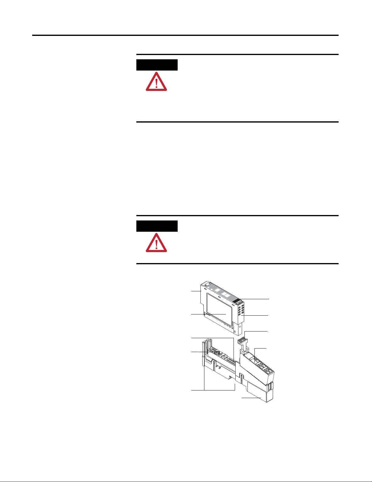
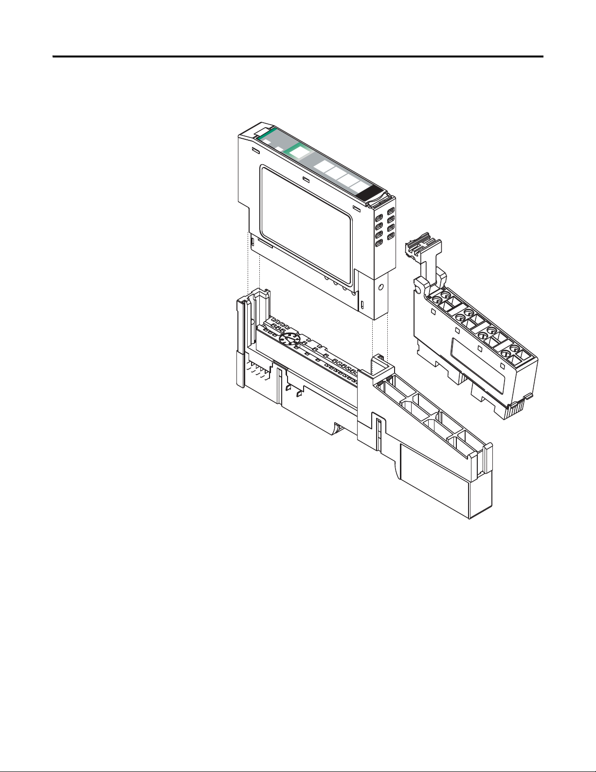
The wiring base assembly (1734-TB or 1734-TBS) consists of the following:
• Mounting base, catalog number 1734-MB
• Removable terminal block, catalog number 1734-RTB or 1734-RTBS
The wiring base assembly (1734-TBCJC) consists of the following:
• Mounting base, catalog number 1734-MB
• Removable terminal block, catalog number 1734-RTBCJC
, Industrial
Publication 1734-UM004F-EN-E - December 2012
Install the Module 9
ATTENTION
ATTENTION
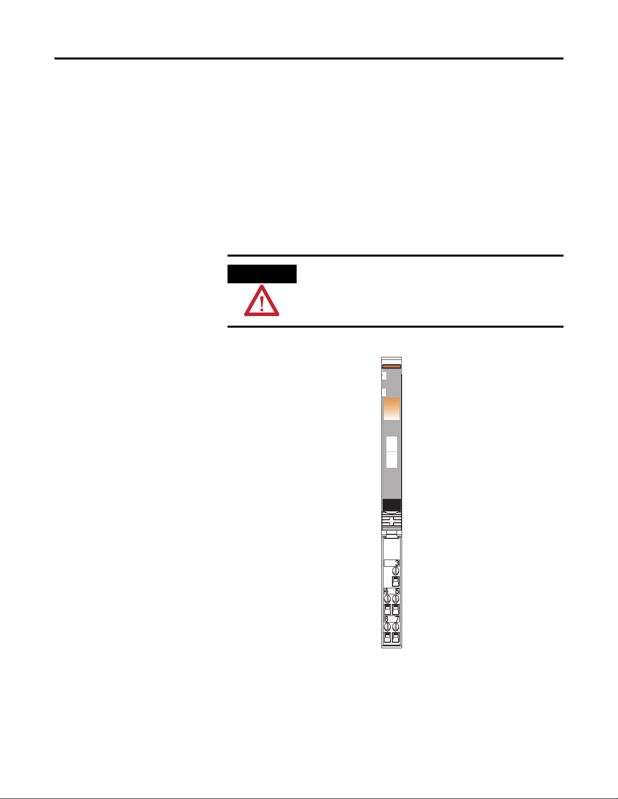
Therm
ocou
ple
Input
Module
Status
Network
Status
N
O
D
E
:
0
1
1
7
3
4
IT
2
I
Removable terminal
block (1734-RTBCJC)
Insertable
I/O module
RTB Removal
Handle
Slide-in writable label
Interlocking
side pieces
Mechanical keying
(orange)
Module wiring
diagram
DIN rail locking
screw (orange)
Module locking
mechanism
Mounting base
46008
POINT I/O is grounded through the DIN rail to chassis ground.
Use zinc-plated, yellow-chromated steel DIN rail to assure
proper grounding. The use of DIN rail materials (such as
aluminum and plastic) that can corrode, oxidize, or are poor
conductors can result in improper or intermittent grounding.
Secure DIN rail to mounting surface approximately every
200 mm (7.8 in.).
You can install the assembly, or just the mounting base.
Follow this procedure to install the mounting base/wiring base assembly on
the DIN rail.
1. Position the mounting base (wiring base) assembly vertically above the
installed units (adapter, power supply, or existing module).
2. Slide the mounting base down so that the interlocking side pieces
engage the adjacent module or adapter.
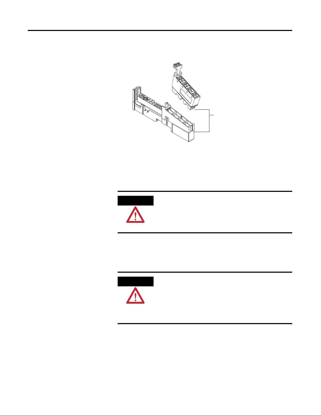
Do not discard the end cap shipped with an adapter or
communication interface. Use this end cap to cover the exposed
interconnections on the last mounting base on the DIN rail.
Failure to do so could result in equipment damage or injury from
electric shock.
1734-IT2I shown
Publication 1734-UM004F-EN-E - December 2012

10 Install the Module
46003
WARNING
3. Press firmly to seat the mounting base on the DIN rail.
The mounting base snaps into place.
Module
Status
Network
Status
N
ODE:
24VDC
Source
Output
0
1
2
3
1734
OB4E
4. Repeat this procedure for the next mounting base assembly.
Install an I/O Module
Install the module before or after base installation. Make sure you correctly
keyed the mounting base before installing the module into the mounting base.
In addition, make sure you positioned the mounting base locking screw
horizontal, referenced to the base.
When you insert or remove the module while backplane power
is on, an electrical arc can occur. This could cause an explosion
in hazardous location installations.
Be sure that power is removed or the area is nonhazardous
before proceeding. Repeated electrical arcing causes excessive
wear to contacts on both the module and its mating connector.
Worn contacts may create electrical resistance that can affect
module operation.
1. Using a bladed screwdriver, rotate the keyswitch on the mounting base
clockwise till the number required for the type of module you are
installing aligns with the notch in the base.
Publication 1734-UM004F-EN-E - December 2012

Install the Module 11
4
5
6
7
8
1
2
3
Turn the keyswitch to align
the number with the notch.
Notch
(position 6 shown)
Make sure the DIN rail locking
screw is in the horizontal position.
1734-RTD - Position 6
1734-IT2I - Position 6
2. Make certain the DIN rail locking screw is in the horizontal position,
noting that you cannot insert the module if the locking mechanism is
unlocked.
Publication 1734-UM004F-EN-E - December 2012
12 Install the Module
24VD
C
Source
Output
Module
Status
Netw
ork
Status
1734
OB4E
NODE:
0
1
2
3
44012
3. Insert the module straight down into the mounting base and press to
secure, locking the module into place.
Install the Removable Terminal Block
A removable terminal block comes with your mounting base assembly. To
remove, pull up on the RTB handle to remove the base and replace, as
necessary, without removing any of the wiring. To reinsert the removable
terminal block, proceed as follows.
Publication 1734-UM004F-EN-E - December 2012
Install the Module 13
WARNING
Hook the RTB end into the
mounting base end, and
rotate until it locks into place.
WARNING
1. Insert the RTB end opposite the handle into the base unit, which has a
curved section that engages with the mounting base.
2. Rotate the terminal block into the mounting base until it locks itself in
place.
3. If an I/O module is installed, snap the RTB handle into place on the
module.
Remove a Mounting Base
When you connect or disconnect the removable terminal block
(RTB) with field-side power applied, an electrical arc can occur.
This could cause an explosion in hazardous location
installations. Be sure that power is removed or the area is
nonhazardous before proceeding.
To remove a mounting base, you must remove any installed module, and
remove the removable terminal block (if wired).
When you connect or disconnect the removable terminal block
(RTB) with field-side power applied, an electrical arc can occur.
This could cause an explosion in hazardous location
installations.
Be sure that power is removed or the area is nonhazardous
before proceeding.
1. Unlatch the RTB handle on the I/O module.
2. Pull on the RTB handle to remove the removable terminal block.
3. Press in on the module lock on the top of the module, and pull up on
the I/O module to remove from the base.
Publication 1734-UM004F-EN-E - December 2012
14 Install the Module
WARNING
43923
Module status
Network status
Status of input 0
Status of input 1
0+
Shield
0-
1+
1-
4. Remove the module to the right of the base you are removing, noting
that the interlocking portion of the base sits under the adjacent module.
5. Use a small-bladed screwdriver to rotate the orange DIN rail locking
screw on the mounting base to a vertical position. releasing the locking
mechanism.
6. Lift the mounting base straight up to remove.
Wire the Modules
To wire the thermocouple input modules, refer to the figures.
If you connect or disconnect wiring while the field-side power
is on, an electrical arc can occur. This could cause an explosion
in hazardous location installations. Be sure that power is
removed or the area is nonhazardous before proceeding.
1734-IT2I Module Overview
Module
Status
Network
Status
NODE:
Thermocouple
Input
0
1
1734
IT2
Publication 1734-UM004F-EN-E - December 2012
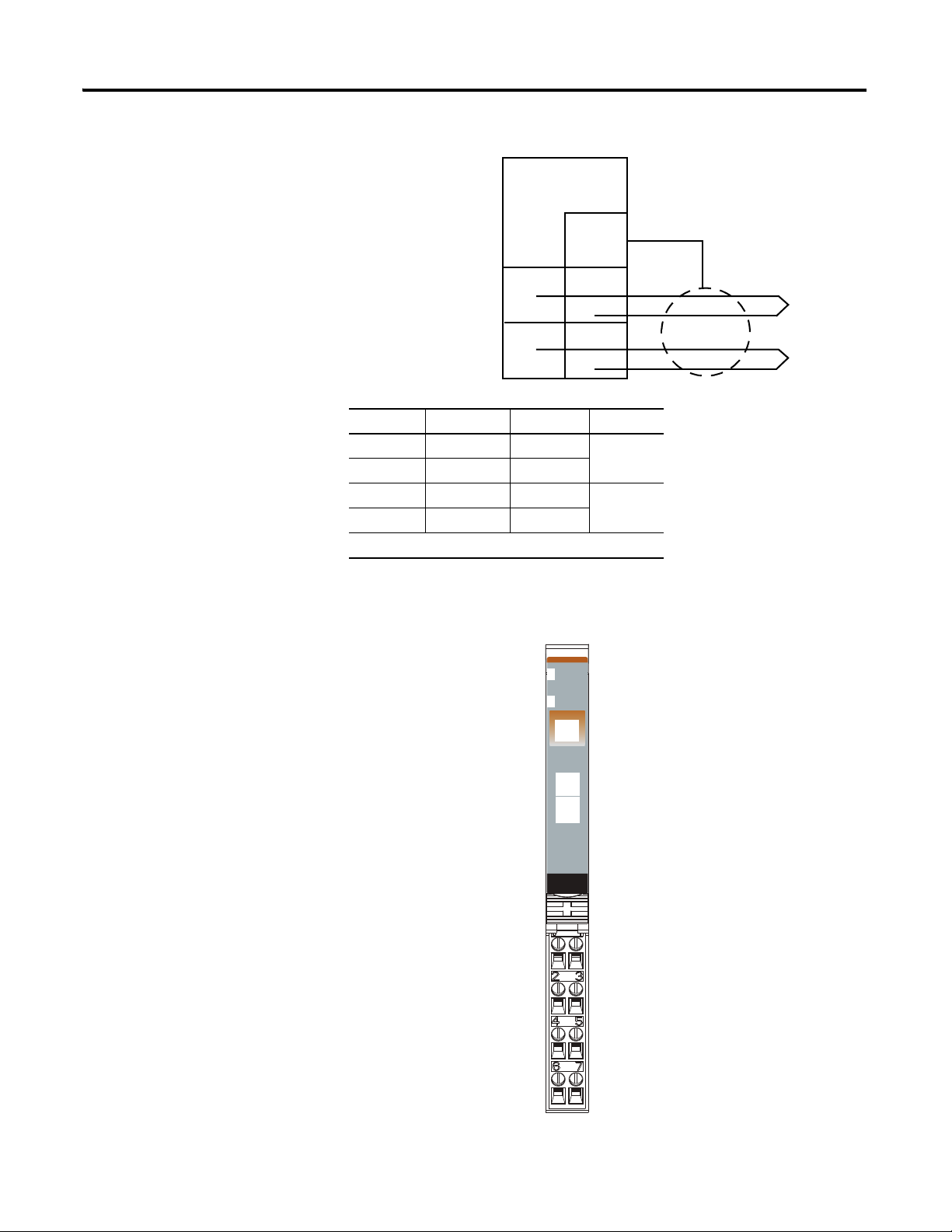
Wiring Diagram
Shield
0+
0-
1-
1+
3
5
7
4
6
Thermocouple 0
Thermocouple 1
0+ = Input channel 0 High
0- = Input channel 0 Low
1+ = Input channel 1 High
1- = Input channel 1 Low
Shld = Shield
46000
Module Status
Network Status
Status of Input 0
Status of Input 1
Input 0/A HIgh Input
Input 0/B Low Input
RET 0
Shield
Input 1/A High Input
Input 1/B Low Input
Shield
RET 1
Input Channel Power Limits
Channel Input High Input Low Shield
0+ 4 3
0- 5
1+ 6 3
1- 7
Power is provided by the internal power bus.
Install the Module 15
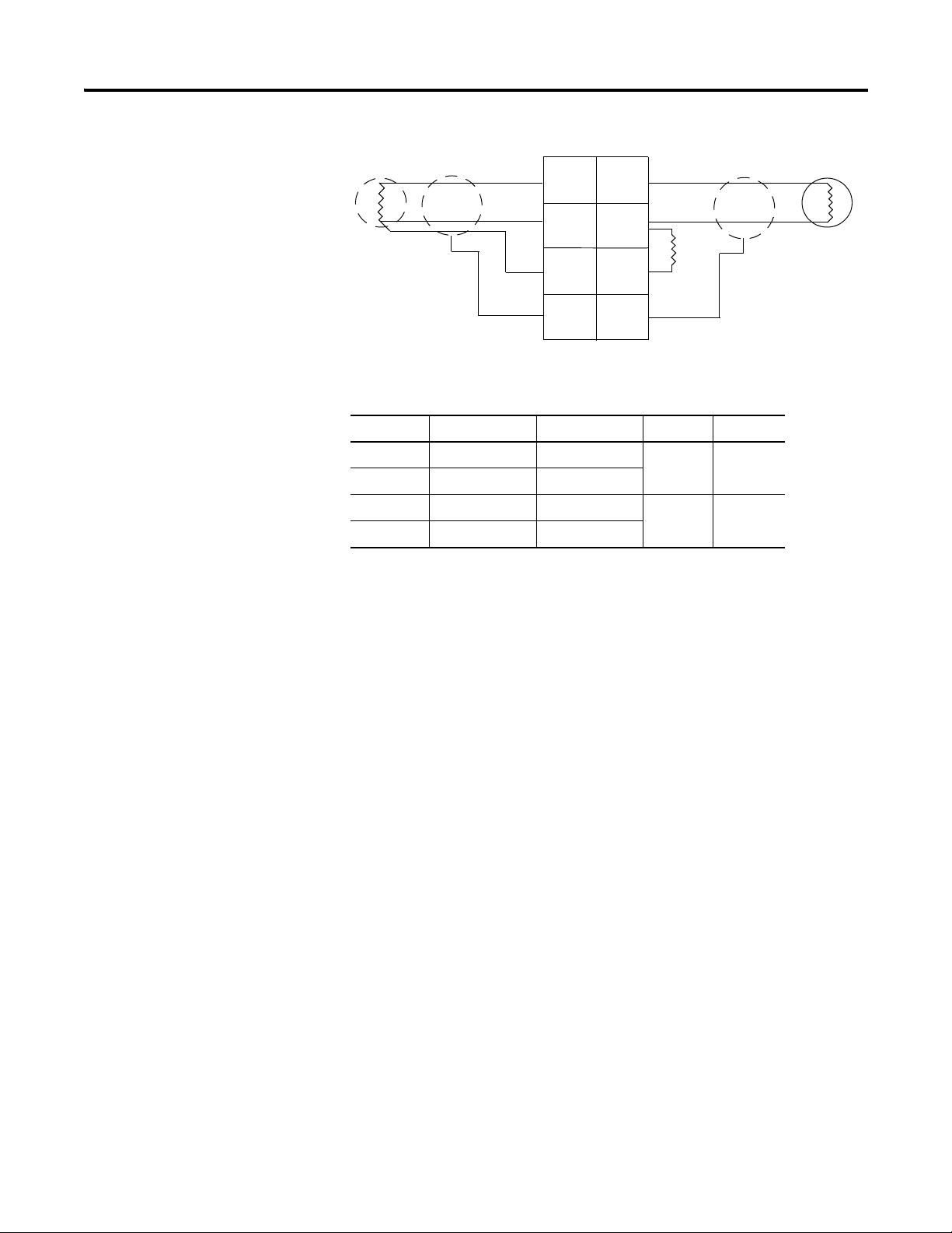
To wire RTD modules, refer to the figures.
1734-IR2, 1734-IR2E Module Overview
Module
Status
Network
Status
NODE:
RTD
Input
0
1
1734
IR2
Publication 1734-UM004F-EN-E - December 2012
16 Install the Module
In 0/A In 1/A
In 1/BIn 0/B
RET 0 RET 1
ShieldShield
3-wire
RTD
In = Input channel
RET = Sensor return
Shield = Sensor cable shield
3
5
0
1
2
4
2-wire
RTD
6
7
When using 2-wire RTDs,
Insert 1 Ω resistor IN/B to
RET.
1 Ω
resistor
Wiring Diagram
Input Channel Power Limits
Channel High Signal (+) Low Signal (-) Return Shield
In 0/A 0 4 6
In 0/B 2
In 1.A 1 5 7
Chapter Summary
In 1/B 3
This chapter explained how to install and wire the modules. The next chapter
describes how to configure your POINT I/O Thermocouple and RTD
Modules.
Publication 1734-UM004F-EN-E - December 2012
Loading...