


Reference Manual
Bulletin 1606 Switched Mode Power Supplies
Catalog Number: 1606-XLE960DX-3N
Index
1. |
Description ........................................................... |
1 |
2. |
Specification Quick Reference ............................ |
1 |
3. |
Catalog Numbers ................................................. |
1 |
4. |
Certification Marks .............................................. |
1 |
5. |
AC Input ............................................................. |
3 |
6. |
Input Inrush Current .......................................... |
4 |
7. |
Output ................................................................. |
5 |
8. |
Hold-up Time....................................................... |
6 |
9. |
Efficiency and Power Losses................................ |
7 |
10. |
Functional Diagram............................................. |
8 |
11. |
Front Side and User Elements............................. |
8 |
12. |
Terminals and Wiring.......................................... |
9 |
13. |
Reliability ............................................................. |
9 |
14. |
EMC .................................................................... |
10 |
15. |
Environment ...................................................... |
11 |
16. Protection Features ........................................... |
12 |
|
17. |
Safety Features .................................................. |
12 |
18. |
Dielectric Strength ............................................ |
12 |
19. |
Certifications ..................................................... |
13 |
|
|
Page |
20. |
Environmental Compliance ........................... |
13 |
21. |
Physical Dimensions and Weight .................... |
14 |
22. |
Installation and Operating Instructions .......... |
14 |
23. |
Accessories ........................................................ |
15 |
24.Comparison between the 1606-XLE960DX-3N, a Transformer and a Traditional Switched-
Mode Power Supply ......................................... |
15 |
|
25. Application Notes ........................................... |
16 |
|
25.1. |
Periodic PeakPower Capability ................. |
16 |
25.2. |
Charging Batteries .................................. |
16 |
25.3. |
Output Circuit Breakers ................ |
17 |
25.4. |
External Input Protection ......................... |
18 |
25.5. |
Back-Feeding Loads ................................... |
18 |
25.6. |
Parallel Use to Increase Output Power .... |
18 |
25.7. |
Parallel Use for Redundancy .................... |
18 |
25.8. |
Series Operation ....................................... |
19 |
25.9. |
Inductive and Capacitive Loads ................ |
19 |
25.10 Loss of One Input Phase ........................... |
19 |
|
25.11. Use in a Tightly Sealed Enclosure ............ |
19 |
|
25.12. Mounting Orientations ............................ |
20 |
|
Terminology and Abbreviations
•PE and  symbol—PE is the abbreviation for Protective Earth and has the same meaning as the symbol
  .
.
•Earth, Ground—This document uses the term “earth” which is the same as the U.S. term “ground”.
•T.b.d.—To be defined, value or description will follow later.
•3AC 400V—A figure displayed with the AC or DC before the value represents a nominal voltage with standard tolerances (usually ±15%) included. 3AC means three phase input. E.g.: DC 12V describes a 12V battery disregarding whether it is charged (13.7V) or discharged (10V). If not otherwise stated, 3AC 400V parameters are valid at 50Hz and 3AC 480V parameters are valid at 60Hz mains frequency.
•3x 400Vac—A figure with the unit (Vac) at the end is a value used during testing without any additional tolerance included. 3x 400Vac means a three phase input.

Bulletin 1606 Switched Mode Power Supplies
 1. Description
The power supplies in the three-phase (-3) series feature a new and innovative concept for generating an isolated DC voltage from a three-phase mains system.
A semi-regulated resonant converter enables a very compact design, maximum efficiency and extremely competitive pricing with only a small compromise in the output voltage regulation, output ripple and hold-up time.
Weighing just 1.4 kg, the device provides 960 watts of continuous output power and an additional 25% power reserve for dynamic loads. The light-weight design along with compact dimensions facilitate straightforward mounting on DIN rail.
Primary use are applications involving supplies to motors, valves and other load circuits with a high power consumption, where an accurate output voltage regulation which is standard on traditional switched-mode power supplies is not required. Furthermore, these switched-mode power supplies can often replace mains transformers with rectifiers.
Semi-Regulated Power Supply
•Alternative or Replacement for AC Transformer
•Three Phase Input – DC Output
•Mountable on a Din Rail
•Width only 96mm
•95.5% Efficiency
•125% Peak Power Capability
•No Input Inrush Current
•Active Input Transient Blocker
•Full Power Between -25°C and +60°C
•Easy Failure Diagnostics
•No Electrolytic Capacitors on Input Side
•Cost Effective and Robust
•3 Year Warranty
 2. Specification Quick Reference
Output voltage |
DC 24V |
Factory setting to |
||
Adjustment range |
none |
24.1V |
||
|
|
|
||
Output current |
40A |
continuous |
|
|
|
50A |
for typ. 15s |
||
Output power |
960W |
continuous |
|
|
|
1200W |
for typ. 15s |
||
Output ripple |
< 1500mVpp |
20Hz-2kHz |
|
|
|
< 200mVpp |
2kHz to 20MHz |
|
|
Input voltage |
3AC 480V |
1606-XLE960DX-3N |
||
Mains frequency |
50-60Hz |
±6% |
|
|
AC Input current |
1.4A / phase |
3x480V |
||
Power factor |
0.93 |
24V, 40A |
||
AC Inrush current |
typ. 2A peak |
|
|
|
Efficiency |
95.5% |
|
|
|
Losses |
45.2W |
|
|
|
Temperature range |
-25°C to +70°C |
operational |
|
|
Derating |
24W/°C |
+60 to +70°C |
||
Dimensions |
96x124x159mm |
WxHxD |
|
|
|
3. Catalog Numbers |
|
|
|
|
4. Certification Marks |
|
|||
|
|
|
|
|
|
|||||
|
|
Power Supply |
|
|
|
|
|
18WM |
|
|
|
|
|
|
|
|
|
|
|
||
|
|
1606-XLE960DX-3N |
480V Input |
|
|
|
||||
|
|
|
LISTED |
|
|
|||||
|
|
|
|
|
|
|
|
|
|
|
|
|
|
|
|
|
|
|
IND. CONT. EQ. |
UL 60950-1 |
|
|
|
|
|
|
|
|
|
UL 508 |
EMC, LVD |
|
|
|
Accessory |
1606-XLSBUFFER24 |
24V Buffer Unit |
|
|||||
|
|
|
|
|
||||||
|
|
|
|
|
|
|
|
Marine RINA |
GOST R |
C-Tick |
|
|
|
|
|
|
|
|
|
||
|
All parameters are specified at 24V, 40A, 3x480Vac, 25°C ambient and after a 5 minutes run-in time, unless noted otherwise. |
2 |
Rockwell Automation Publication 1606-RM024A-EN-P — April 2014 |
Bulletin 1606 Switched Mode Power Supplies
Intended Use
•This device is designed for installation in an enclosure and is intended for the general professional use such as in industrial control, office, communication, and instrumentation equipment.
•Do not use this power supply in aircraft, trains, nuclear equipment or similar systems where malfunction may cause severe personal injury or threaten human life.
•This device is designed for use in non-hazardous, ordinary or unclassified locations.
Installation Requirements
•This device may only be installed and put into operation by qualified personnel.
•This device does not contain serviceable parts. The tripping of an internal fuse is caused by an internal defect.
•If damage or malfunction should occur during installation or operation, immediately turn power off and send unit to the factory for inspection.
•Mount the unit on a DIN rail so that the terminals are located on the bottom of the unit. For other mounting orientations, refer to section 25-14 in this document.
•This device is designed for convection cooling and does not require an external fan. Do not obstruct airflow and do not cover ventilation grid (e.g. cable conduits) by more than 30%!
•Keep the following installation clearances: 40mm on top, 20mm on the bottom, 5mm on the left and right sides are recommended when the device is loaded permanently with more than 50% of the rated power. Increase this clearance to 15mm in case the adjacent device is a heat source (e.g. another power supply).
SHOCK HAZARD: Do not use the power supply without proper grounding (Protective Earth). Use the terminal on the input block for earth connection and not one of the screws on the housing.
-Turn power off before working on the device. Protect against inadvertent re-powering
-Make sure that the wiring is correct by following all local and national codes
-Do not modify or repair the unit
-Do not open the unit as high voltages are present inside
-Use caution to prevent any foreign objects from entering the housing
-Do not use in wet locations or in areas where moisture or condensation can be expected
-Do not touch during power-on, and immediately after power-off. Hot surfaces may cause burns.
WARNING: EXPLOSION HAZARDS!
Substitution of components may impair suitability for this environment. Do not disconnect the unit or operate the voltage adjustment or S/P jumper unless power has been switched off or the area is known to be non-hazardous.
All parameters are specified at 24V, 40A, 3x480Vac, 25°C ambient and after a 5 minutes run-in time, unless noted otherwise. |
|
Rockwell Automation Publication 1606-RM024A-EN-P — April 2014 |
3 |
Bulletin 1606 Switched Mode Power Supplies
 5. AC-Input
1606-XLE960DX-3N
AC input |
nom. |
3AC 480V |
|
|
Mains arrangement |
|
TN-, TTor IT-Mains. Consult factory if one phase is grounded. |
||
AC input range |
min. |
3x 432-528Vac fully regulated output (±2%), Pout > 48W |
||
|
|
min. |
3x 360-552Vac permanently allowed, |
|
|
|
|
*) |
see Fig. 5-1 for output voltage regulation |
|
|
max. |
3x 565Vac |
Absolute maximum input voltage with no |
|
|
|
|
damage to the power supply. Output |
|
|
|
|
might be off at this level. |
|
|
|
|
|
Input frequency |
nom. |
50 – 60Hz |
±6% |
|
Turn-on voltage |
typ. |
3x 390Vac |
see Fig. 5-2 |
|
Shut-down voltage |
typ. |
3x 355Vac |
see Fig. 5-2 |
|
Input current |
nom. |
1.4A |
at 40A, symmetrical input, see Fig. 5-4 |
|
Power factor **) |
typ. |
0.93 |
at 40A, symmetrical input, see Fig. 5-5 |
|
Turn-on overshoot |
typ. |
480mV |
see Fig. 5-3 |
|
Start-up delay ***) |
typ. |
350ms |
over the entire load range, see Fig. 5-3 |
|
Rise time |
typ. |
40ms |
0mF, 40A, see Fig. 5-3 |
|
|
|
typ. |
70ms |
40mF, 40A, see Fig. 5-3 |
*) |
A minimum voltage of 3x408Vac is required to turn the power supply on. |
|
||
**) |
The power factor is the ratio of the true (or real ) power to the apparent power in an AC circuit. |
|||
***) |
The start-up delay for mains voltage interruptions up to 350ms is close to zero. In such cases, the power supply will |
|||
|
immediately generate the output voltage once the mains voltage interruption is over. Do not use the 1606-XLSBUFFER24 |
|||
|
buffer module as an accessory when longer mains interruptions need to be bridged (see section 23). |
|||
Input Voltage Range |
|
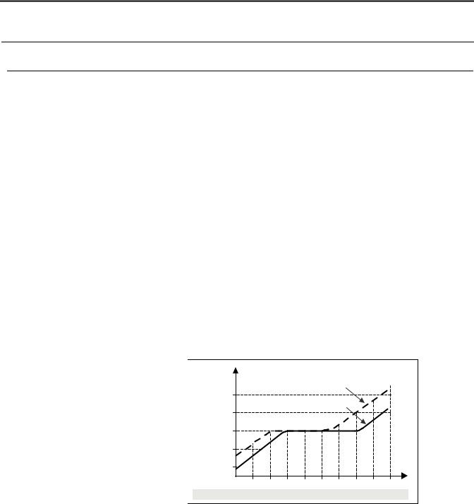
Fig. 5-1 Output voltage vs. input voltage and input current |
||
Changes of the input voltage will be fully regulated within certain limits. The output voltage will only start to change proportionally to the input voltage with extreme under or over-voltages. The yellow LED reports an input voltage problem if exceeded by a window of ±15%. The maximum increase of the output voltage is limited to the 29.9V OVP level. This level will be kept regulated for 2s before the power supply will shut down and re ports “Shut-down” by the red LED.
VOUT |
|
|
|
|
|
|
|
|
28V |
|
|
|
|
P OUT = 0W |
|
|
|
|
|
|
|
|
|
|
|
|
26V |
|
|
|
P OUT > 48W (5%) |
|
|
|
|
|
|
|
|
|
|
|
|
|
24V |
|
|
|
|
|
|
|
|
22V |
|
|
|
|
|
|
|
|
20V |
|
|
|
|
|
|
|
VIN |
1606-XLE: |
360 |
384 |
408 |
432 |
456 480 504 |
528 |
552 |
576Vac |
|
All parameters are specified at 24V, 40A, 3x480Vac, 25°C ambient and after a 5 minutes run-in time, unless noted otherwise. |
4 |
Rockwell Automation Publication 1606-RM024A-EN-P — April 2014 |

Bulletin 1606 Switched Mode Power Supplies
|
Fig. 5-2 Input Voltage Range |
||
POUT |
|
fully regulated |
|
|
|
|
range |
Shut-down |
Turn-on |
|
V IN |
400V Version: |
3x 360Vac |
3x 440Vac |
|
480V Version: |
3x 432Vac |
3x 528Vac |
|
Fig. 5-4 Input current vs. output load
Input Current per Phase, typ.
1.8A
1.5
1.2
0.9
0.6
0.3
Output Current
0 


 5 10 15 20 25 30 35 40 45 50A
Fig. 5-3 Turn-on behavior definitions
Intput |
|
|
|
Voltage |
|
|
|
Output |
- 5% |
|
Overshoot |
|
|
||
Voltage |
|
|
|
|
Start-up |
Rise |
|
|
delay |
Time |
|
Fig. 5-5 Power factor vs. output load |
|||
Power Factor, typ.
1.0 |
|
|
|
|
|
|
|
|
0.95 |
|
|
|
|
|
|
|
|
0.9 |
|
|
|
|
|
|
|
|
0.85 |
|
|
|
|
|
|
|
|
0.8 |
|
|
|
|
|
|
|
|
0.75 |
|
|
|
|
|
Output Current |
||
0.70 |
|
|
|
|
|
|||
|
|
|
|
|
|
|
|
|
5 |
10 |
15 |
20 |
25 |
30 |
35 |
40 45 |
50A |
 6. Input Inrush Current
There is virtually no input inrush current surge as there are no electrolytic bulk-capacitors used on the input side of the power supply.
The charging current into the EMI suppression capacitors is disregarded for the first millisecond after switch-on.
|
|
1606-XLE960DX-3N |
|
Inrush current |
max. |
4A peak |
-25°C to +70°C, see Fig. 6-1 |
Inrush energy |
max. |
5A2s |
-25°C to +70°C, see Fig. 6-1 |
Inrush delay |
typ. |
350ms |
see Fig. 6-1 |
Fig. 6-1 Input inrush current
Input Current
A
Input Voltage
Output Voltage
All parameters are specified at 24V, 40A, 3x480Vac, 25°C ambient and after a 5 minutes run-in time, unless noted otherwise. |
|
Rockwell Automation Publication 1606-RM024A-EN-P — April 2014 |
5 |
Bulletin 1606 Switched Mode Power Supplies
7. Output
Output voltage |
nom. |
24.1V |
|
|
|
Output voltage adjustment range |
|
none |
The output voltage is fixed. No adjustment possible. |
||
Output current |
nom. |
40A |
continuous, see Fig. 7-1 |
|
|
|
|
50A |
up to 15s with full output voltage, see Fig. 7-1 |
||
Short-circuit current |
typ. |
180A |
load impedance 25mOhm, seeFig. 7-1 |
||
|
|
|
Note: The short-circuit current is available for 0.1s. |
||
Output power |
nom. |
960W |
continuous |
|
|
|
|
1200W |
up to 15s |
|
|
Line regulation |
max. |
±2% |
seeFig. 5-1 |
|
|
Load regulation |
max. |
800mV |
static value, 0A |
40A |
0A |
|
max. |
200mV |
static value, 5A |
40A |
5A |
Ripple and noise voltage *) |
max. |
1500mVpp |
20Hz-2kHz, 50Ohm |
|
|
|
max. |
50mVpp |
2kHz to 20MHz, 50Ohm |
|
|
Output capacitance |
typ. |
20 000μF |
|
|
|
*) The ripple and noise voltage mostly consist of a mains ripple with 300Hz (50Hz mains) or 360Hz (60Hz mains). The ripple and noise voltage can be reduced by using external capacitors.
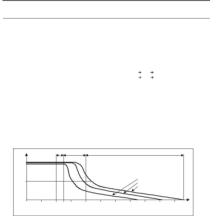
The power supply is also designed to support loads with a higher short-term current and power requirement. The short-term duration is firmware-controlled by an output power manager. If the nominal output power is exceeded for a certain period of time which is defined in zone A, B and C, the power supply responds with an automatic shutdown. Pressing the reset button or cycling the input power (10s off time is required) initiates a restart attempt.
If the fault has been cleared the device will operate normally.
The short term power can be used periodically . See section 25.1 for further information.
|
|
|
|
Fig. 7-1 Output voltage vs. output current, typ. |
|
|
|
|||||
VOUT |
|
|
A |
B |
|
|
|
C |
|
|
|
|
|
15s |
5s |
|
|
|
0.1s |
|
|
|
|
||
|
|
|
|
|
|
|
|
|
||||
24V |
|
|
|
|
|
|
|
|
|
|
|
|
12V |
|
|
|
|
|
|
|
|
3x 408V |
|
|
|
|
|
|
|
|
|
|
|
3x 480V |
|
|
|
|
|
|
|
|
|
|
|
|
|
|
|
|
|
|
|
|
|
|
|
|
|
|
3x 552V |
|
|
|
0 |
20A |
40A |
50A 60A |
80A |
100A |
120A |
140A |
160A |
180A |
200A |
IOUT |
|
Zone A : 25% extra output power for typ. 15s
Zone B: 100% higher output current for typ. 5s
Zone C: Quick-acting shut-down after typ. 0.1s
|
All parameters are specified at 24V, 40A, 3x480Vac, 25°C ambient and after a 5 minutes run-in time, unless noted otherwise. |
6 |
Rockwell Automation Publication 1606-RM024A-EN-P — April 2014 |
|
|
|
|
|
|
Bulletin 1606 Switched Mode Power Supplies |
|
|
|
|
|
|
|
|
|
|
|
8. Hold-up Time |
|
|
|
|
|
|
|
|
|
|
|
||
|
|
|
|
|
1606-XLE960DX-3N |
||
|
|
|
|
|
|||
|
|
|
Hold-up Time |
typ. |
2.0ms |
40A, resistive load, see Fig. 8-2 |
|
|
|
|
|
typ. |
1.8ms |
40A, constant power load, see Fig. 8-2 |
|
|
|
|
|
typ. |
4.0ms |
20A, resistive load |
|
|
|
|
|
typ. |
3.6ms |
20A, constant power load |
|
|
|
|
Hold-up Time |
min. |
1.6ms |
40A, resistive load, see Fig. 8-2 |
|
|
|
|
|
min. |
1.45ms |
40A, constant power load, see Fig. 8-2 |
|
|
|
|
|
min. |
3.2ms |
20A, resistive load |
|
|
|
|
|
min. |
2.9ms |
20A, constant power load |
|
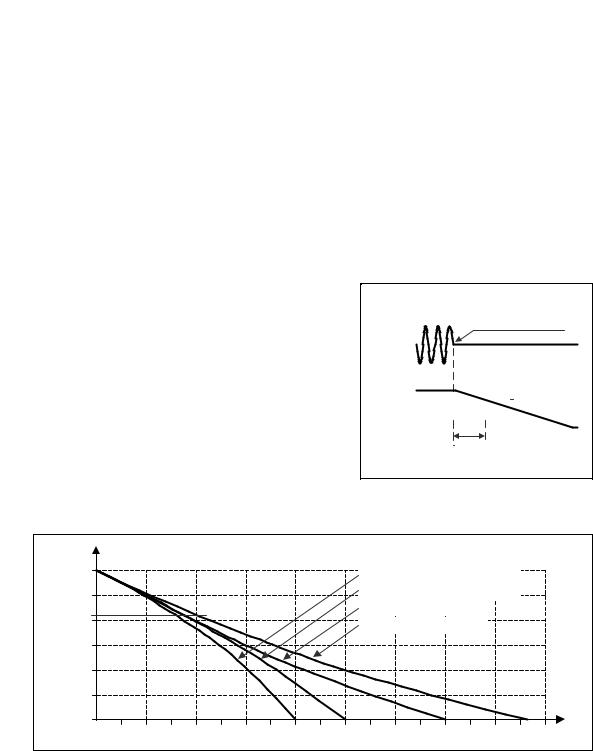
The energy is stored in the output capacitor. As soon as the input is turned off, the output capacitor will be discharged and the voltage will dissipate according to the curves in Fig 8-2.
The lighter the load, the longer the hold-up time. Half the load means twice the hold-up time.
The hold-up time depends on the load characteristic. The curves below show the hold-up time for a load with a resistive and a constant power characteristic.
The hold-up time is defined as the period of time when the input is turned off and until the output voltage falls below 24V –15% (20.4V). This value is defined in the IEC61131-2 as the lower limit for the supplying voltage.
Fig. 8-1 Hold-up time, definitions
Zero Transition
Intput
Voltage
Output |
|
Hold- |
|
|
|
-15% |
Voltage |
|
|
|
|
|
|
|
up |
|
|
|
|
|
|
|
|
|
|
Time
|
|
|
|
|
Fig. 8-2 Hold-up time vs. input voltage |
|
|
|
|
|
|||||||
V OUT |
|
|
|
|
|
|
|
|
|
|
|
|
|
|
|
|
|
24V |
|
|
|
|
|
|
|
|
|
40A, constant power load, min. |
|
|
|||||
22V |
|
|
|
|
|
|
|
|
|
40A, constant power load, typ. |
|
|
|||||
|
|
|
|
|
|
|
|
|
|
|
|
|
|
|
|
|
|
20.4V |
|
|
|
|
|
|
|
|
|
40A, resistive load, min. |
|
|
|
||||
|
|
|
|
|
|
|
|
|
40A, resistive load, typ. |
|
|
|
|||||
|
|
|
|
|
|
|
|
|
|
|
|
|
|||||
18V |
|
|
|
|
|
|
|
|
|
|
|
|
|
|
|
|
|
16V |
|
|
|
|
|
|
|
|
|
|
|
|
|
|
|
|
|
14V |
|
|
|
|
|
|
|
|
|
|
|
|
|
|
|
|
T |
12V |
|
|
|
|
|
|
|
|
|
|
|
|
|
|
|
|
|
|
|
|
|
|
|
|
|
|
|
|
|
|
|
|
|
|
|
0.5 |
1.0 |
1.5 |
2.0 |
2.5 |
3.0 |
3.5 |
4.0 |
4.5 |
5.0 |
5.5 |
6.0 |
6.5 |
7.0 |
7.5 |
8.0 |
8.5 |
9.0ms |
Note: At no load, the hold-up time can be up to one minute. The green DC-ok LED is on at this time.
All parameters are specified at 24V, 40A, 3x480Vac, 25°C ambient and after a 5 minutes run-in time, unless noted otherwise. |
|
Rockwell Automation Publication 1606-RM024A-EN-P — April 2014 |
7 |
 Loading...