


 Loading...
DeviceNet™
Communication
Module
Catalog Number 160-DN2
Firmware 3.xxx
User Manual

Important User Information Solid state equipment has operational characteristics differing from those of electromechanical equipment. “Safety Guidelines for the Application, Installation and Maintenance of Solid State Controls” (Publication SGI-1.1 available from your local Rockwell Automation Sales Office or online at http://www.ab.com/manuals/gi) describes some important differences between solid state equipment and hard-wired electromechanical devices. Because of this difference, and also because of the wide variety of uses for solid state equipment, all persons responsible for applying this equipment must satisfy themselves that each intended application of this equipment is acceptable.
In no event will Rockwell Automation, Inc. be responsible or liable for indirect or consequential damages resulting from the use or application of this equipment.
The examples and diagrams in this manual are included solely for illustrative purposes. Because of the many variables and requirements associated with any particular installation, Rockwell Automation, Inc. cannot assume responsibility or liability for actual use based on the examples and diagrams.
No patent liability is assumed by Rockwell Automation, Inc. with respect to use of information, circuits, equipment, or software described in this manual.
Reproduction of the contents of this manual, in whole or in part, without written permission of Rockwell Automation, Inc. is prohibited.
Throughout this manual we use notes to make you aware of safety considerations.
ATTENTION: Identifies information about practices or
!circumstances that can lead to personal injury or death, property
damage, or economic loss.
Attentions help you:
•identify a hazard
•avoid the hazard
•recognize the consequences
Important: Identifies information that is especially important for successful application and understanding of the product.
Shock Hazard labels may be located on or inside the drive to alert people that dangerous voltage may be present.
DeviceNet is a trademark of the Open DeviceNet Vendor Association.
SSC is a registered trademark of Rockwell Automation, Inc.
Allen-Bradley, ControlLogix, PLC-5, and SLC are trademarks of Rockwell Automation, Inc.
RSLinx, RSLogix, and RSNetWorx for DeviceNet are trademarks of Rockwell Software.

Summary of Changes
The information below summarizes the changes made to this manual since its last release (March, 1999):
Location |
Description of Changes |
Chapter 3 Added three new sections — Surge-Suppression, Common Mode Noise, and Output Disconnect — after the Low Voltage Directive 73/23/EEC Compliance section.
Chapter 5 Added EDS file search screen and removed obsolete Table 6 (EDS files for Bulletin 160 using a 160-DN2 version 3.000 or later).
Chapter 6 Replaced DeviceNet Manager software references and screens with those of RSNetWorx for DeviceNet. Added I/O and explicit messaging information and ladder logic examples for ControlLogix, PLC-5, and SLC controllers.
Chapter 7 In the “Understanding the FAULT LED” section, added Bulletin 160 Fault Codes 11, 20, 36, and 46 to the table on pages 7-3 and 7-4.
Appendix B In section “Class Code 0xB3 — 160 Parameter Table Object” in the “Instance 1 Attributes” chart on pages B-18 and B-19, corrected the Data Types for these Attribute IDs:
Attribute ID |
Parameter Name |
Data Type |
9 |
Drive Status |
WORD (was USINT) |
10 |
Drive Type |
USINT (was UINT) |
12 |
Input Status |
WORD (was USINT) |
15 |
Preset Status |
WORD (was USINT) |
33 |
Maximum Freq |
UINT (was USINT) |
35 |
Base Frequency |
UINT (was USINT) |
39 |
Skip Frequency |
UINT (was USINT) |
In section “Class Code 0x04 — Assembly Objects,” subsection “Instance Data Format: Output Assemblies” on page B-24, added new footnotes for Instance 21 in bit 5 and bit 6 columns. Re-arranged numerical order of all footnotes on this page.
In section “Class Code 0x04 — Assembly Objects,” subsection “Instance Data Format: Output Assemblies” on page B-25, added a new footnote for Instance 101 in bit 0, bit 1, and bit 2 columns. Re-arranged numerical order of all footnotes on this page.
In section “Class Code 0x04 — Assembly Objects,” subsection “Configuration Assembly Data Formats,” deleted unnecessary Instance 190 table (pages B-29 through B-34).
Publication 0160-5.18 - June 2003

S-2 |
Summary of Changes |
The March 1999 release of the Bulletin 160-DN2 DeviceNet Communication Module User Manual covers the software enhancements of Firmware Version 3.xxx and contains new and updated information.
Bulletin 160-DN2 version 3.xxx |
Features and enhancements in the 160-DN2 module that are different |
Software Enhancements |
than those in the 160-DN1 module include: |
|
|
Compatibility with Bulletin 160 drives |
Bulletin 160 (Series A, B, and C) drives can be connected to a |
(Series A, B, and C) |
DeviceNet network. |
Ability to Create Electronic Data Sheets |
Configuration tools, such as DeviceNet Manager, can create an |
|
Electronic Data Sheet (EDS file) for the 160 SSC drive and 160-DN2 |
|
module. |
Added Parameter Object |
This object describes the parameters in the 160 SSC drive and |
|
160-DN2 module. |
Added Parameter Group Object |
This object describes the parameter groups associated with the |
|
160 SSC drive and 160-DN2 module. |
New and Revised Chapters to The bulletin 160-DN2 DeviceNet Communication Module User
this Manual Manual, Publication 0160-5.18, is a new manual. It is, however, similar to the 160 DeviceNet Communication Module User Manual,
Publication 0160-5.5. The main differences can be found in the following chapters:
Using This Manual |
Preface |
Quick Start for Experienced Users |
Chapter 2 |
DeviceNet Parameter Descriptions |
Chapter 5 |
Using the 160-DN2 with DeviceNet Scanner |
Chapter 6 |
Troubleshooting |
Chapter 7 |
DeviceNet Information |
Appendix B |
Summary of Enhancements to User Manual
Refer to the following references in this manual:
Reference Manuals Section |
P-2 |
Manual Organization |
P-3 |
DeviceNet Compatibility |
P-4 |
Replacing a 160-DN1 with a 160-DN2 |
P-4 |
Required Tools and Equipment |
3-1 |
DeviceNet Parameter Descriptions |
Chapter 5 |
Creating EDS Files replaces Installing EDS Files |
6-3 |
Troubleshooting Updated |
Chapter 7 |
Parameter Object |
B-9 |
Parameter Group Object |
B-11 |
Acknowledge Handler Object |
B-17 |
Publication 0160-5.18 - June 2003

|
Table of Contents |
|
Using This Manual |
Preface |
|
Manual Objectives. . . . . . . . . . . . . . . . . . . . . . . . . . . . . . . . . . . . . . . . . . . . . . . |
. P-1 |
|
|
Who Should Use This Manual?. . . . . . . . . . . . . . . . . . . . . . . . . . . . . . . . . . . . . . |
P-1 |
|
Product References . . . . . . . . . . . . . . . . . . . . . . . . . . . . . . . . . . . . . . . . . . . . . . |
P-1 |
|
Conventions . . . . . . . . . . . . . . . . . . . . . . . . . . . . . . . . . . . . . . . . . . . . . . . . . . . . |
P-1 |
|
Firmware Version . . . . . . . . . . . . . . . . . . . . . . . . . . . . . . . . . . . . . . . . . . . . . . . . |
P-1 |
|
Related Documentation. . . . . . . . . . . . . . . . . . . . . . . . . . . . . . . . . . . . . . . . . . . . |
P-2 |
|
Manual Organization . . . . . . . . . . . . . . . . . . . . . . . . . . . . . . . . . . . . . . . . . . . . . . |
P-2 |
|
Safety Precautions . . . . . . . . . . . . . . . . . . . . . . . . . . . . . . . . . . . . . . . . . . . . . . . |
P-3 |
|
DeviceNet Compatibility . . . . . . . . . . . . . . . . . . . . . . . . . . . . . . . . . . . . . . . . . . . |
P-4 |
|
Replacing a 160-DN1 with a 160-DN2 . . . . . . . . . . . . . . . . . . . . . . . . . . . . . . . . |
P-4 |
|
Rockwell Automation Support . . . . . . . . . . . . . . . . . . . . . . . . . . . . . . . . . . . . . . . |
P-4 |
|
Chapter 1 |
|
Product Overview |
Module Description . . . . . . . . . . . . . . . . . . . . . . . . . . . . . . . . . . . . . . . . . . . . . . . |
1-1 |
|
LEDs and DeviceNet Connection . . . . . . . . . . . . . . . . . . . . . . . . . . . . . . . . . . . . |
1-1 |
|
DIP Switches. . . . . . . . . . . . . . . . . . . . . . . . . . . . . . . . . . . . . . . . . . . . . . . . . . . . |
1-2 |
|
Chapter 2 |
|
Quick Start for |
Introduction . . . . . . . . . . . . . . . . . . . . . . . . . . . . . . . . . . . . . . . . . . . . . . . . . . . . . |
2-1 |
Experienced Users |
Required Tools and Equipment. . . . . . . . . . . . . . . . . . . . . . . . . . . . . . . . . . . . . . |
2-1 |
|
Procedures . . . . . . . . . . . . . . . . . . . . . . . . . . . . . . . . . . . . . . . . . . . . . . . . . . . . . |
2-2 |
|
Chapter 3 |
|
Installation and Wiring |
Required Tools and Equipment . . . . . . . . . . . . . . . . . . . . . . . . . . . . . . . . . . . . . |
3-1 |
|
EMC Directive 89/336/EEC Compliance. . . . . . . . . . . . . . . . . . . . . . . . . . . . . . . |
3-2 |
|
Low Voltage Directive 73/23/EEC Compliance . . . . . . . . . . . . . . . . . . . . . . . . . . |
3-2 |
|
Surge Suppression . . . . . . . . . . . . . . . . . . . . . . . . . . . . . . . . . . . . . . . . . . . . . . . |
3-2 |
|
Common Mode Noise . . . . . . . . . . . . . . . . . . . . . . . . . . . . . . . . . . . . . . . . . . . . |
3-4 |
|
Drive Output Disconnect . . . . . . . . . . . . . . . . . . . . . . . . . . . . . . . . . . . . . . . . . . |
3-4 |
|
Removing Program Keypad Module or Ready/Fault Panel . . . . . . . . . . . . . . . . |
3-5 |
|
Understanding Module Configuration Switches . . . . . . . . . . . . . . . . . . . . . . . . . |
3-5 |
|
Setting the DeviceNet Node Address . . . . . . . . . . . . . . . . . . . . . . . . . . . . . . . . . |
3-6 |
|
Setting the Baud Rate. . . . . . . . . . . . . . . . . . . . . . . . . . . . . . . . . . . . . . . . . . . . . |
3-7 |
|
Cable Lengths and Baud Rates . . . . . . . . . . . . . . . . . . . . . . . . . . . . . . . . . . . |
3-7 |
|
Installing the Communication Module . . . . . . . . . . . . . . . . . . . . . . . . . . . . . . . . . |
3-8 |
|
Wiring the DeviceNet Connector. . . . . . . . . . . . . . . . . . . . . . . . . . . . . . . . . . . . . |
3-9 |
|
Connecting the DeviceNet Drop Line to the Module . . . . . . . . . . . . . . . . . . . . . |
3-10 |
|
Removing Communication Module From a Drive . . . . . . . . . . . . . . . . . . . . . . |
3-10 |
Publication 0160-5.18 - June 2003

ii |
Table of Contents |
Modes of Operation
DeviceNet Parameter
Descriptions
Using 160-DN2 with DeviceNet Scanner
Chapter 4
Powering Up the Drive . . . . . . . . . . . . . . . . . . . . . . . . . . . . . . . . . . . . . . . . . . . . 4-1
Modes of Operation. . . . . . . . . . . . . . . . . . . . . . . . . . . . . . . . . . . . . . . . . . . . . . . 4-1
Power-up Reset Mode. . . . . . . . . . . . . . . . . . . . . . . . . . . . . . . . . . . . . . . . . . . 4-1
Run Mode . . . . . . . . . . . . . . . . . . . . . . . . . . . . . . . . . . . . . . . . . . . . . . . . . . . . 4-2
Error Mode . . . . . . . . . . . . . . . . . . . . . . . . . . . . . . . . . . . . . . . . . . . . . . . . . . . 4-2
Chapter 5
DeviceNet Parameters . . . . . . . . . . . . . . . . . . . . . . . . . . . . . . . . . . . . . . . . . . . . 5-1
Electronic Data Sheet (EDS) Files . . . . . . . . . . . . . . . . . . . . . . . . . . . . . . . . . . . 5-1
Parameters and EDS File . . . . . . . . . . . . . . . . . . . . . . . . . . . . . . . . . . . . . . . . . . 5-1 Bulletin 160 SSC Interface . . . . . . . . . . . . . . . . . . . . . . . . . . . . . . . . . . . . . . . . . 5-2
Locating EDS Files on the Internet . . . . . . . . . . . . . . . . . . . . . . . . . . . . . . . . . . . 5-2
Bulletin 160 SSC Interface Parameters . . . . . . . . . . . . . . . . . . . . . . . . . . . . . . . 5-3 DeviceNet Parameters . . . . . . . . . . . . . . . . . . . . . . . . . . . . . . . . . . . . . . . . . . . . 5-3 Drive Display Parameters (Read Only) . . . . . . . . . . . . . . . . . . . . . . . . . . . . . . . . 5-6
Drive Program Parameters . . . . . . . . . . . . . . . . . . . . . . . . . . . . . . . . . . . . . . . . . 5-8
Chapter 6
Needed Tools . . . . . . . . . . . . . . . . . . . . . . . . . . . . . . . . . . . . . . . . . . . . . . . . . . . 6-2
Setting Device MAC ID’s. . . . . . . . . . . . . . . . . . . . . . . . . . . . . . . . . . . . . . . . . . . 6-2 Using RSNetWorx for DeviceNet . . . . . . . . . . . . . . . . . . . . . . . . . . . . . . . . . . . . 6-2
Going Online . . . . . . . . . . . . . . . . . . . . . . . . . . . . . . . . . . . . . . . . . . . . . . . . . . 6-2
Creating an EDS File . . . . . . . . . . . . . . . . . . . . . . . . . . . . . . . . . . . . . . . . . . . 6-3 Accessing and Editing Parameters . . . . . . . . . . . . . . . . . . . . . . . . . . . . . . . . . 6-4
Selecting Input and Output Assemblies for I/O Messaging . . . . . . . . . . . . . . . . 6-5
Changing the Output Assembly . . . . . . . . . . . . . . . . . . . . . . . . . . . . . . . . . . . 6-6
Changing the Input Assembly . . . . . . . . . . . . . . . . . . . . . . . . . . . . . . . . . . . . . 6-6
Enabling Network Control . . . . . . . . . . . . . . . . . . . . . . . . . . . . . . . . . . . . . . . . . . 6-7
Configuring Drive Input Mode . . . . . . . . . . . . . . . . . . . . . . . . . . . . . . . . . . . . 6-7
Modifying Drive Reset Functions . . . . . . . . . . . . . . . . . . . . . . . . . . . . . . . . . . 6-8 Configuring the 160 to Accept Speed Commands from the Network . . . . . . . . . 6-9 Configuring the Scanner . . . . . . . . . . . . . . . . . . . . . . . . . . . . . . . . . . . . . . . . . . 6-10
Example Network . . . . . . . . . . . . . . . . . . . . . . . . . . . . . . . . . . . . . . . . . . . . . 6-10 Setting Up the Scan List . . . . . . . . . . . . . . . . . . . . . . . . . . . . . . . . . . . . . . . . 6-11 Mapping the Drive Data in the Scanner . . . . . . . . . . . . . . . . . . . . . . . . . . . . 6-13 Saving the Configuration. . . . . . . . . . . . . . . . . . . . . . . . . . . . . . . . . . . . . . . . 6-16 Using I/O Messaging. . . . . . . . . . . . . . . . . . . . . . . . . . . . . . . . . . . . . . . . . . . . . 6-16 Example Ladder Logic Programs . . . . . . . . . . . . . . . . . . . . . . . . . . . . . . . . . 6-16 ControlLogix Example . . . . . . . . . . . . . . . . . . . . . . . . . . . . . . . . . . . . . . . . . 6-17 PLC-5 Example . . . . . . . . . . . . . . . . . . . . . . . . . . . . . . . . . . . . . . . . . . . . . . 6-19
SLC Example . . . . . . . . . . . . . . . . . . . . . . . . . . . . . . . . . . . . . . . . . . . . . . . . 6-21
Using Explicit Messaging . . . . . . . . . . . . . . . . . . . . . . . . . . . . . . . . . . . . . . . . . 6-23 About Explicit Messaging . . . . . . . . . . . . . . . . . . . . . . . . . . . . . . . . . . . . . . . 6-23 Formatting Explicit Messages . . . . . . . . . . . . . . . . . . . . . . . . . . . . . . . . . . . . 6-23
Executing Explicit Messages. . . . . . . . . . . . . . . . . . . . . . . . . . . . . . . . . . . . . 6-29
Publication 0160-5.18 - June 2003

Table of Contents iii
|
Chapter 7 |
|
Troubleshooting |
Understanding the COMM LED . . . . . . . . . . . . . . . . . . . . . . . . . . . . . . . . . . . . |
. 7-2 |
|
Understanding the FAULT LED . . . . . . . . . . . . . . . . . . . . . . . . . . . . . . . . . . . . . |
7-3 |
Specifications |
Appendix A |
|
Electrical . . . . . . . . . . . . . . . . . . . . . . . . . . . . . . . . . . . . . . . . . . . . . . . . . . . . . |
A-1 |
|
|
Environmental . . . . . . . . . . . . . . . . . . . . . . . . . . . . . . . . . . . . . . . . . . . . . . . . |
A-1 |
|
Communications . . . . . . . . . . . . . . . . . . . . . . . . . . . . . . . . . . . . . . . . . . . . . . |
A-1 |
|
Mechanical . . . . . . . . . . . . . . . . . . . . . . . . . . . . . . . . . . . . . . . . . . . . . . . . . . . |
A-1 |
DeviceNet Information |
Appendix B |
|
DeviceNet Message Types . . . . . . . . . . . . . . . . . . . . . . . . . . . . . . . . . . . . . . . . . |
B-1 |
|
|
Object Classes . . . . . . . . . . . . . . . . . . . . . . . . . . . . . . . . . . . . . . . . . . . . . . . . . . |
B-2 |
|
Supported Data Types . . . . . . . . . . . . . . . . . . . . . . . . . . . . . . . . . . . . . . . . . . . . |
B-2 |
|
Class Code 0x01 — Identity Object . . . . . . . . . . . . . . . . . . . . . . . . . . . . . . . . |
B-3 |
|
Class Code 0x03 — DeviceNet Object . . . . . . . . . . . . . . . . . . . . . . . . . . . . . . |
B-5 |
|
Class Code 0x05 — Connection Object . . . . . . . . . . . . . . . . . . . . . . . . . . . . . |
B-6 |
|
Class Code 0x0F — Parameter Object. . . . . . . . . . . . . . . . . . . . . . . . . . . . . . |
B-9 |
|
Class Code 0x10 — Parameter Group Object . . . . . . . . . . . . . . . . . . . . . . . |
B-11 |
|
Class Code 0x28 — Motor Data Object . . . . . . . . . . . . . . . . . . . . . . . . . . . . |
B-12 |
|
Class Code 0x29 — Control Supervisor Object . . . . . . . . . . . . . . . . . . . . . . |
B-13 |
|
State Transition Diagram . . . . . . . . . . . . . . . . . . . . . . . . . . . . . . . . . . . . . . |
B-14 |
|
Run/Stop Event Matrix . . . . . . . . . . . . . . . . . . . . . . . . . . . . . . . . . . . . . . . |
B-15 |
|
Class Code 0x2A — AC Drive Object . . . . . . . . . . . . . . . . . . . . . . . . . . . . . . |
B-16 |
|
Class Code 0x2B — Acknowledge Handler Object . . . . . . . . . . . . . . . . . . . |
B-17 |
|
Class Code 0xB3 — 160 Parameter Table Object . . . . . . . . . . . . . . . . . . . . |
B-18 |
|
Class Code 0xB4 — DN Interface Object . . . . . . . . . . . . . . . . . . . . . . . . . . . |
B-22 |
|
Class Code 0x04 — Assembly Objects . . . . . . . . . . . . . . . . . . . . . . . . . . . . |
B-23 |
|
Instance Data Format: Output Assemblies . . . . . . . . . . . . . . . . . . . . . . . . |
B-24 |
|
Instance Data Format: Input Assemblies . . . . . . . . . . . . . . . . . . . . . . . . . |
B-26 |
|
Configuration Assembly Data Formats . . . . . . . . . . . . . . . . . . . . . . . . . . . |
B-29 |
Index
Publication 0160-5.18 - June 2003

iv |
Table of Contents |
Publication 0160-5.18 - June 2003

|
Preface |
|
|
Using This Manual |
|
Manual Objectives |
The purpose of this manual is to provide you with the necessary |
|
|
information to apply the Bulletin 160 SSC DeviceNet |
|
|
Communication Module. This manual describes methods to install, |
|
|
configure, and troubleshoot the Bulletin 160 SSC DeviceNet |
|
|
Communication Module. |
|
|
For information on specific features of the Bulletin 160 SSC drive, |
|
|
refer to the Bulletin 160 SSC User Manual. |
|
|
Important: Read this manual in its entirety before installing, |
|
|
operating, servicing, or initializing the Bulletin 160 DeviceNet |
|
|
Communication Module. |
|
Who Should Use This Manual? |
This manual is intended for qualified personnel. To make efficient use |
|
|
of the Communication Module, you must be able to program and |
|
|
operate serial communications devices, as well as have an |
|
|
understanding of the parameter settings and functions of the Bulletin |
|
|
160 SSC drive. |
|
|
You should understand DeviceNet network operations, including how |
|
|
slave devices operate on the network and communicate with a |
|
|
DeviceNet master. |
|
Product References |
In this manual we refer to the: |
|
|
• Bulletin 160-DN2 DeviceNet Communication Module as |
|
|
Communication Module and Module. |
|
|
• Bulletin 160 SSC Variable Frequency AC Drive as the Drive. |
|
Conventions |
Parameter names are shown in the format PXX - [*] where P denotes |
|
|
parameter, XX represents the parameter number, and * represents the |
|
|
parameter name. For example, P01 - [Output Frequency]. |
|
Firmware Version |
The firmware release is displayed as FRN X.xxx, where: |
|
FRN |
= |
Firmware Release Number |
X |
= |
Firmware (whole) Number |
(.) |
= |
Decimal point separator |
xxx |
= |
Place holders representing minor updates |
Places to the right of the decimal do not affect content of this manual.
Publication 0160-5.18 - June 2003

P-2 |
Using This Manual |
Related Documentation
For: |
Refer to: |
Publication |
|
|
|
Bulletin 160 SSC |
User Manual Series A |
0160-5.0 |
Drive |
User Manual Series B |
0160-5.9 |
|
User Manual Series C |
0160-5.15 |
|
|
|
RSNetWorx for |
RSNetWorx for DeviceNet Getting Results Guide |
9398-DNETGR |
DeviceNet Software |
Online help (installed with the software) |
|
|
|
|
ControlLogix |
ControlLogix User Manual |
1756-6.5.13 |
|
|
|
SLC 500 and |
DeviceNet Scanner Module Installation Instructions |
1747-5.8 |
1747-SDN |
DeviceNet Scanner Module Configuration Manual |
1747-6.5.2 |
|
|
|
PLC5 |
DeviceNet Scanner Module Installation Instructions |
1771-5.14 |
and 1771-SDN |
DeviceNet Scanner Module Configuration Manual |
1771-6.5.118 |
|
|
|
DeviceNet Cables |
DeviceNet Product Overview |
DN-2.5 |
and Components |
|
|
|
|
|
DeviceNet Network |
DeviceNet Cable System Planning and Installation |
DN-6.7.2 |
Installation |
Manual |
|
|
|
|
Important: Read the DeviceNet Cable System Planning and Installation Manual, Publication DN-6.7.2, in its entirety before planning and installing a DeviceNet system. If the network is not installed according to this document, unexpected operation and intermittent failures can occur.
|
Documentation can be obtained online at http://www.ab.com/manuals. |
|||
Manual Organization |
This 160-DN2 Module user manual contains the following sections: |
|||
|
|
|
|
|
|
|
Chapter |
Title |
Contents |
|
|
|
|
|
|
|
Preface |
Using This Manual |
Manual objectives, audience, vocabulary, manual |
|
|
|
|
conventions and organization, safety precautions, |
|
|
|
|
and DeviceNet compatibility. |
|
|
|
|
|
|
1 |
Product Overview |
Module description, LEDs, DIP switches, and |
|
|
|
|
|
DeviceNet compatibility. |
|
|
|
|
|
|
2 |
Quick Start for |
Communication Module features, configuration, |
|
|
|
|
Experienced Users |
and diagnostics. |
|
|
|
|
|
|
3 |
Installation and Wiring |
Installation, switch configuration, cabling, and |
|
|
|
|
|
removal. |
|
|
|
|
|
|
4 |
Modes of Operation |
Power-up and modes of operation. |
|
|
|
|
|
|
|
5 |
DeviceNet Parameter |
EDS file parameters, Bulletin 160 SSC interface, |
|
|
|
|
Descriptions |
product codes. |
|
|
|
|
|
|
6 |
Using 160-DN2 with |
Mac IDs, RSNetWorx for DeviceNet, configuration, |
|
|
|
|
DeviceNet Scanner |
input/output assemblies, network control, scan list, |
|
|
|
|
I/O messaging, ladder program examples, explicit |
|
|
|
|
messaging. |
|
|
|
|
|
|
7 |
Troubleshooting |
LED indications and fault descriptions. |
|
|
|
|
|
|
|
|
Appendix A |
Specifications |
Environmental, electrical, and communication |
|
|
|
|
specifications. |
|
|
|
|
|
|
|
Appendix B |
DeviceNet Information |
DeviceNet message types and object classes. |
|
|
|
|
|
Publication 0160-5.18 - June 2003
|
Using This Manual |
P-3 |
|
Safety Precautions |
Please read the following safety precautions carefully: |
|
|
ATTENTION: Risk of injury or death exists. The drive contains high voltage capacitors which take time
! to discharge after removal of mains supply. Before installing or removing the DeviceNet Communication Module, make sure to isolate the mains supply from line inputs [L1, L2, L3 (R, S, T)]. Wait three minutes for capacitors to discharge to safe voltage levels. Failure to do so may result in injury or death.
ATTENTION: Risk of injury or equipment damage exists. Only personnel familiar with DeviceNet devices,
! Bulletin 160 SSC drives, and associated machinery should plan or implement the installation, start-up, configuration, and subsequent maintenance of the Communication Module. Failure to comply may result in injury and/or equipment damage.
ATTENTION: Risk of equipment damage exists. This module contains ESD (Electrostatic Discharge)
! sensitive parts that can be damaged if you do not follow ESD control procedures. Static control precautions are required when handling this Communication Module. If you are unfamiliar with static control procedures, refer to Guarding Against Electrostatic Damage, Publication 8000-4.5.2.
ATTENTION: Risk of injury or equipment damage exists. When a system is configured for the first time, ! there may be unintended or incorrect machine motion.
Disconnect the motor from the machine or process during initial system testing.
ATTENTION: Hazard of equipment damage exists. If explicit messages are programmed to frequently change ! parameter data in the drive, the EEPROM will quickly exceed its life cycle and cause the drive to malfunction.
Do not create a program that frequently uses explicit messages to change a parameter in the drive.
Publication 0160-5.18 - June 2003

P-4 |
Using This Manual |
DeviceNet Compatibility
Replacing a 160-DN1 with a 160-DN2
Rockwell Automation Support
The 160-DN2 Communication Module is intended for use only with Bulletin 160 SSC Series A, Bulletin 160 SSC Series B, and Bulletin 160 SSC Series C (FRN 7.03 and later) devices. Bulletin 160 SSC (Series C) devices must use a 160-DN2 Communication Module to connect to a DeviceNet network. Bulletin 160 SSC (Series A and B) devices can use either a 160-DN2 or 160-DN1 Communication Module to connect to a DeviceNet network.
When properly connected, the Communication Module communicates via the DeviceNet Protocol. The Communication Module/Bulletin 160 SSC combination comprise a Group 2 Slave Only device. This device supports DeviceNet slave Polled, Change of State/Cyclic messaging, and DeviceNet slave Explicit messaging. It does not support the Explicit Unconnected Message Manager (UCMM).
You can replace a 160-DN1 Communication Module with a 160-DN2 Communication Module on any 160 SSC (Series A and Series B) drive. To do so, you will need to create an EDS file for the new 160DN2 Communication Module and map the module to the network. Chapter 6, Using 160-DN2 with DeviceNet Scanner, provides detailed instructions on how to perform these tasks.
Rockwell Automation, Inc. offers support services worldwide, with over 75 sales/support offices, over 500 authorized distributors, and over 250 authorized systems integrators located through the United States alone. In addition, Rockwell Automation, Inc. representatives are in every major country in the world.
Local Product Support — Contact your local Rockwell Automation, Inc. representative for sales and order support, product technical training, warranty support, and support service agreements.
Technical Product Assistance — If you need to contact Rockwell Automation, Inc. for technical assistance, please review the information in Chapter 7, Troubleshooting first. If you still have problems, then call your local Rockwell Automation, Inc. representative.
U.S. Allen-Bradley Drives Technical Support:
E-mail: support@drives.ra.rockwell.com
Tel: (1) 262.512.8176
Fax (1) 262.512.2222
Online: www.ab.com/support/abdrives
UK Customer Support Center:
E-mail: esupport2@ra.rockwell.com
Tel: +44 (0) 870 2411802
Fax: +44 (0) 1908 838804
Germany Customer Service Center:
E-mail: ragermany-csc@ra.rockwell.com
Tel: +49 (0) 2104 960-630
Fax: +49 (0) 2104 960-501
Publication 0160-5.18 - June 2003

Chapter 1
|
Product Overview |
|
This chapter contains the following information: |
|
• physical layout of the module |
|
• location of configuration switches |
|
• DeviceNet overview and components |
Module Description |
The Bulletin 160 SSC DeviceNet Communication Module is an |
|
optional interface device designed to provide a direct, digital link |
|
between DeviceNet devices and the Bulletin 160 SSC drive. The |
|
module connects to the Bulletin 160 SSC through the expansion/ |
|
keypad port on the front of the drive. |
LEDs and DeviceNet Connection
Figure 1.1
Module Front View
Module Installation Latch
TM
CONFORMANCE TESTED
Ready LED - GREEN when drive is powered up
Fault LED - RED when drive is faulted
OFF when drive not faulted
COMM - This bi-colored LED (red/green) provides status information on DeviceNet communications
DeviceNet Terminal Block Plug - The Communication Module receives power and communications through this connector.
See Chapter 4, Modes of Operation, and Chapter 7, Troubleshooting, for detailed operation.
Publication 0160-5.18 - June 2003

1-2 |
Product Overview |
DIP Switches
Figure 1.2
Module Rear View
The Communication Module has one eight position DIP switch for setting the DeviceNet Node Address and Baud Rate. DIP switches are located on the rear of the module and are only accessible when the module is removed from the Bulletin 160 SSC drive.
SW.7 - SW.8 = Baud Rate Selection (see page 3-7)
Label with DeviceNet Serial Number
 Expansion/Keypad Port Connector
SW.1 - SW.6 = Node Address Selection  (see page 3-6)
Publication 0160-5.18 - June 2003

Chapter 2
|
Quick Start for Experienced Users |
Introduction |
This chapter can help you start using the Bulletin 160 DeviceNet |
|
Communication module. If you have previously installed or |
|
configured a DeviceNet network and are familiar with Rockwell |
|
Automation DeviceNet modules and drives, this information can help |
|
reduce installation and startup time. If you are uncertain, use the full |
|
installation/configuring information beginning in Chapter 3. |
|
We base the procedures listed in this chapter on the assumption that |
|
you understand DeviceNet concepts and know how to program the |
|
Bulletin 160 SSC drive. You should also be able to understand |
|
electronic process control and interpret the ladder logic instructions |
|
required to generate the electronic signals that control your |
|
application. |
|
Because it is a start-up guide for experienced users, this chapter does |
|
not contain detailed explanations about the procedures listed. It does, |
|
however, reference other chapters in this book where you can get |
|
more information. |
|
If you have any questions or are unfamiliar with the terms used or |
|
concepts presented in the procedural steps, always read the |
|
referenced chapters and other recommended documentation before |
|
trying to apply the information. |
|
The information contained in this chapter includes: |
|
• What tools and equipment you will need. |
|
• When to address, configure, and program the module. |
|
• How to install and wire the Communication Module. |
|
• System power-up procedures. |
Required Tools and Equipment |
Have the following tools and equipment ready: |
|
• small blade screwdriver |
|
• DeviceNet configuration software or hardware device |
Publication 0160-5.18 - June 2003

2-2 |
Quick Start for Experienced Users |
Procedures
Step |
|
|
Refer to . . . |
|
|
|
|
1 |
Review Attention statements in the Preface. |
Preface |
|
|
|
|
|
2 |
Check the contents of the shipping box. |
— |
|
|
Unpack the shipping box, making sure that it contains: |
|
|
|
• |
Bulletin 160 DeviceNet module (Catalog Number 160-DN2) |
|
|
• |
10-pin linear plug with probe holes and jack screws |
|
|
• |
DeviceNet Communication Module 160-DN2 User Manual |
|
|
If the contents are incomplete, call your local Allen-Bradley |
|
|
|
representative for assistance. |
|
|
|
|
|
|
3 |
Ensure that the drive is correctly installed and wired. (The |
Publication 160-SSC |
|
|
Stop Input, TB3-7 and TB3-8, must be jumpered together |
User Manual |
|
|
to start the drive.) |
|
|
|
|
|
|
4 |
Ensure that the DeviceNet master and network are |
DeviceNet Cable |
|
|
installed and functioning by DeviceNet standards. |
System Planning and |
|
|
|
|
Installation Manual |
|
|
|
(Publication DN-6.7.2) |
|
|
|
|
5 |
Remove the Program Keypad Module or |
Chapter 3, |
|
|
Ready/Fault Indicating Panel from the drive. |
Installation and Wiring |
|
|
|
|
|
6 |
Set the DeviceNet Module’s node address and baud rate. |
Chapter 3, |
|
|
Set the DIP Switches at the back of the module. Switches 1 |
Installation and Wiring |
|
|
through 6 set the node address; switches 7 and 8 set baud |
|
|
|
rate. |
|
|
|
|
|
|
7 |
Install the DeviceNet module on the drive. |
Chapter 3, |
|
|
|
|
Installation and Wiring |
|
|
|
|
8 |
Wire the DeviceNet connector and plug it into the drive. |
Chapter 3, |
|
|
|
|
Installation and Wiring |
|
|
|
|
9 |
Power up the drive and the network. |
Chapter 3, |
|
|
|
|
Installation and Wiring, |
|
Important: When power-up occurs, the COMM |
Chapter 4, |
|
|
(communication status) LED flashes green for 1/4 second, red |
Modes of Operation, |
|
|
for 1/4 second, and then goes blank while the Communication |
and |
|
|
Module finishes its initialization. If the COMM LED goes red, |
Chapter 7, |
|
|
there is a problem. |
Troubleshooting |
|
|
|
|
|
10 |
Select the appropriate Electronic Data Sheet (EDS) file. |
Chapter 6, |
|
|
Select the EDS file with the DeviceNet software or hardware |
Using 160-DN2 with |
|
|
configurator that you are using to configure the Communication |
DeviceNet Scanner, |
|
|
Module (see Chapter 5 for EDS file descriptions). |
and DeviceNet |
|
|
|
|
Software or Hardware |
|
|
|
Configurator Manual |
|
|
|
|
11 |
Configure the Bulletin 160 SSC drive for DeviceNet so that |
Chapter 6, |
|
|
the drive can accept speed reference and control logic via |
Using 160-DN2 with |
|
|
the network. |
DeviceNet Scanner |
|
|
Use configuration software such as RSNetWorx for DeviceNet |
|
|
|
or hardware such as DeviceView Hand Held DeviceNet |
|
|
|
Configurator. |
|
|
|
|
|
|
12 |
Configure the DeviceNet Scanner to recognize the Bulletin |
Chapter 6, |
|
|
160 SSC drive. |
Using 160-DN2 with |
|
|
Use RSNetWorx for DeviceNet to configure the DeviceNet |
DeviceNet Scanner |
|
|
Scanner’s “Scan List” to recognize the Bulletin 160 SSC drive. |
|
|
|
|
|
|
Publication 0160-5.18 - June 2003
Chapter 3
Installation and Wiring
This chapter contains information necessary to:
•Meet requirements for CE compliance (EMC / Low Voltage directives).
•Suppress transient EMI from “hard contact” load switching.
•Reduce high frequency common mode noise current.
•Properly connect/disconnect power to the motor.
•Remove a preinstalled Program Keypad Module or Ready/Fault Indicating Panel.
•Configure and install the Communication Module.
•Wire the DeviceNet communication cables.
•Remove an installed Communication Module from the drive.
Read this chapter completely before you attempt to install or configure the Communication Module. Before you apply power, review the Safety Precautions on Preface page P-3, making sure that all connections are secure and all selections are correct.
! |
ATTENTION: When you make changes to the |
switch settings, use a blunt pointed instrument. Do not |
|
use a pencil or pen because damage may occur. |
|
|
|
|
|
! |
ATTENTION: Unpredictable operation may occur if |
you fail to check connections and DIP switch settings |
|
for compatibility with your application. Unpredictable |
|
|
operation may result in personal injury, death, and |
|
equipment damage. |
|
|
Required Tools and Equipment |
Before installing and configuring the 160-DN2 Communication |
|
|
Module, make sure that the contents of the shipping box include: |
|
|
• Bulletin 160-DN2 module (Catalog Number 160-DN2) |
|
|
• |
10 pin linear Plug (Part Number 1787-PLUG10R) |
|
• |
this manual |
In addition, you will need to supply:
•a small blade screwdriver
•DeviceNet configuration software or hardware device
•DeviceNet thick cable or thin cable. For details and part numbers, refer to the DeviceNet Product Overview, Publication DN-2.5.
Publication 0160-5.18 - June 2003

3-2 |
Installation and Wiring |
EMC Directive 89/336/EEC Compliance
Low Voltage Directive 73/23/EEC Compliance
Surge Suppression
The 160-DN2 Communication Module complies with Electromagnetic Compatibility (EMC) Directive 89/336/EEC when conforming to these installation requirements:
•Applying the essential requirements for a conforming EMC installation for the Bulletin 160 SSC drive. Refer to the Bulletin 160 SSC User Manual.
•Connecting the DeviceNet cable shield to the SSC drive’s protective earth terminal, PE, with a low impedance connection.
•Installing a clamp-on ferrite cable clamp (see Figure 3.9) on the DeviceNet communication cable within 10 cm (4 in.) of the SSC drive. When multiple SSC drives are contained in one control cabinet, it is sufficient to install one clamp-on ferrite cable clamp where the DeviceNet communication cable enters the control cabinet.
The 160-DN2 Communication Module complies with Low Voltage Directive 73/23/EEC when conforming to these installation requirements:
•Applying the essential requirements for a conforming Low Voltage Directive installation for the Bulletin 160 SSC drive. Refer to the
Bulletin 160 SSC User Manual.
•Observing the Safety Precautions on Preface page P-3, and other Attention statements throughout this manual when installing the module.
Transient EMI can be generated whenever inductive loads such as relays, solenoids, electro-mechanical brakes, motor starters, or motors are operated by “hard contacts.” The wiring guidelines contained herein are based on the assumption that you safeguard your system against the effects of transient EMI by using surge suppressors to suppress transient EMI at its source. Inductive loads switched by only solid-state output devices do not require surge suppression. However, inductive loads that are in series or parallel with hard contacts require surge suppression to protect control circuits as well as to suppress transient EMI.
Even if regularly cycled inductive loads have no interaction with the control system, these loads need suppression if their conductors are:
•Connected to the same separately derived system as that of the control system.
•Routed in proximity with conductors of the control system (per routing guidelines).
The application (voltage and load of the inductive circuit) dictates the specific suppressor needed at the source of the inductive load. Testing has determined that the best overall RC surge suppressor combination
Publication 0160-5.18 - June 2003
Installation and Wiring |
3-3 |
|
|
|
|
is 220 ohms and 0.50 microfarads. Select the voltage rating for the normal AC voltages. A typical surge suppressor that can be used for most transient EMI problems is Electrocube part number RG1676-16 (rated 480V ac).
Surge suppressors are usually most effective when connected at the inductive loads. However, you can also connect surge suppressors at the switching devices, but they may be less effective because the wires connecting the switching devices to the inductive loads act as antennas that radiate EMI. You can evaluate the effectiveness of a particular suppressor by using an oscilloscope to observe the voltage waveform on the line.
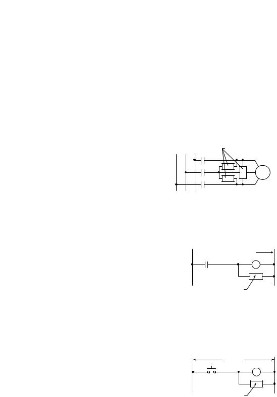
Figure 3.1
Surge Suppressor Connection for 3-Phase Apparatus
230/460VAC |
Surge Suppressor |
3-Phase Motor
For 3-phase apparatus, a suppressor is needed across each phase
Figure 3.2
Surge Suppressor Connection for Large Apparatus
 115/230/460VAC
Surge Suppressor
For large apparatus (electro-mechanical brakes, contacts up to size 5)
Figure 3.3
Surge Suppressor Connection for Small Apparatus
115VAC
Surge Suppressor
For small apparatus (relays, solenoids, and motor starters up to size 1)
Publication 0160-5.18 - June 2003

3-4 |
Installation and Wiring |
|
Common Mode Noise |
To greatly reduce high frequency common mode noise current |
|
|
|
coupled to ground in high capacitance connections, connect a |
|
|
common mode choke at the drive end of the motor cable. The |
|
|
common mode choke reduces the rise time of the high frequency |
|
|
noise by a factor of 10-20, and the amplitude by a factor of 5. For |
|
|
multiple 460 volt drive installations with sensitive equipment (e.g. |
|
|
PLC’s, temperature sensors, sonar detectors, strain gauges, etc.) |
|
|
sharing a common ground separated by more than 30 feet, you must |
|
|
install common mode chokes at the outputs of each drive. |
|
|
In addition to greatly reducing high frequency common mode noise |
|
|
induced by the drive, a common mode choke also effectively reduces |
|
|
high frequency common mode noise that is induced by regularly |
|
|
cycled inductive loads. In installations where inductively-coupled |
|
|
common mode noise causes system problems, connect a common |
|
|
mode choke at the source of the inductively-switched load. |
|
|
For drives on a DeviceNet network, we highly recommend connecting |
|
|
a common mode choke at the drive end of the motor cable. |
Drive Output Disconnect |
The drive is intended to be commanded by control signals that will |
|
|
|
start and stop the motor. Do not use a device that routinely connects |
|
|
or disconnects output power to the motor with the drive outputting |
|
|
power (for the purpose of starting and stopping the motor, or for |
machine positioning). Connecting or disconnecting power to the motor with the drive outputting power can produce transient EMI which can cause network problems to occur.
For emergency stop conditions, make sure that terminal 7 and 8 on TB2 is broken (opened) using an auxiliary contact of a motor output contactor. Also, remember to set the Stop Select parameter to “Coast to Stop.”
Publication 0160-5.18 - June 2003
Installation and Wiring |
3-5 |
|
|
|
|
Removing Program Keypad Module or Ready/Fault Panel
Before installing the Communication Module, it may be necessary to remove a previously installed module such as a Program Keypad Module or Ready/Fault Indicating panel.
ATTENTION: Risk of injury or death exists. The drive contains high voltage capacitors which take time
! to discharge after removal of mains supply. Before installing or removing the DeviceNet Communication Module, make sure to isolate the mains supply from line inputs [L1, L2, L3 (R, S, T)]. Wait three minutes for capacitors to discharge to safe voltage levels. Failure to do this may result in injury or death.
Figure 3.4
Removing Program Keypad Module
Insert a small screw driver into the slot, pry back, and pivot module out. Avoid bending or twisting the contact pins located underneath the center portion of the module.
|
|
|
|
10 |
11 |
|
|
|
9 |
|
|
|
|
|
|
|
|
|
SEL |
6 |
8 |
|
|
ESC |
|
7 |
|
|
|
|
4 |
|
|
|
|
|
|
5 |
|
|
|
|
|
3 |
|
|
|
|
|
2 |
|
|
|
|
|
1 |
|
|
|
|
|
|
|
|
+ |
|
|
|
|
|
DC |
|
|
|
|
|
– |
|
|
|
|
|
DC |
|
|
|
T3 W |
||
|
|
T2 V |
|
|
|
|
|
T1 U |
|
|
|
Program Keypad Module
ESC |
SEL |
|
|
60 |
|
|
11 |
| |
|
|
10 |
|
50 |
|
9 |
|
|
|
8 |
|
|
|
7 |
|
|
|
|
|
|
|
|
|
6 |
|
|
|
|
5 |
|
|
|
|
4 |
|
|
|
|
3 |
|
|
|
|
2 |
|
|
|
|
1 |
|
|
|
|
|
|
|
|
+ |
|
|
|
|
DC |
|
|
|
|
– |
|
|
|
|
DC |
|
|
T3 W |
||
T2 V |
|
|
|
|
T1 U |
|
|
|
|
Understanding Module
Configuration Switches
The Communication Module’s DIP switch settings determine:
•DeviceNet node address
•DeviceNet baud rate
The location of the DIP switch and the factory defaults are shown below.
Figure 3.5
DIP Switches on Rear of Module
DIP Switch |
ON = 1 |
Factory Settings |
OFF = 0 |
8 |
7 |
6 |
5 |
4 |
3 |
12 |
N O |
8 |
7 |
6 |
5 |
4 |
3 |
12 |
N O |
Important: When setting the Communication Module’s addressing DIP Switches, make sure that each serial device on the network has a unique address. Also, all devices connected to the network must be set at the same baud rate.
Publication 0160-5.18 - June 2003

3-6 |
Installation and Wiring |
Setting the DeviceNet Node
Address
DIP switches 6 through 1 set the module’s node address using binary addressing. The factory default setting is DeviceNet address 63.
Figure 3.6
Setting the Node Address
8 |
7 |
6 |
5 |
4 |
3 |
12 |
N O |
DeviceNet Address 000000 - 111111 (0 to 63)
ON = 1
OFF = 0
To set the DeviceNet node address:
1.Refer to Table 3.A below for the switch settings of a specific address.
2.Using a pointed tool, slide switches 6 through 1 to the appropriate ON/OFF positions.
Important: When switches 7 and 8 are ON, the DeviceNet address is set to the value in parameter P103 - [NV MAC ID].
Table 3.A Switch Settings for DeviceNet Node Addressing
DeviceNet |
Switch Settings |
|
DeviceNet |
Switch Settings |
|
DeviceNet |
Switch Settings |
|
DeviceNet |
Switch Settings |
Address |
6 <---- 1 |
|
Address |
6 <---- 1 |
|
Address |
6 <---- 1 |
|
Address |
6 <---- 1 |
|
|
|
|
|
|
|
|
|
|
|
0 |
000000 |
16 |
010000 |
32 |
100000 |
48 |
110000 |
|||
|
|
|
|
|
|
|
|
|
|
|
1 |
000001 |
17 |
010001 |
33 |
100001 |
49 |
110001 |
|||
|
|
|
|
|
|
|
|
|
|
|
2 |
000010 |
18 |
010010 |
34 |
100010 |
50 |
110010 |
|||
|
|
|
|
|
|
|
|
|
|
|
3 |
000011 |
19 |
010011 |
35 |
100011 |
51 |
110011 |
|||
|
|
|
|
|
|
|
|
|
|
|
4 |
000100 |
20 |
010100 |
36 |
100100 |
52 |
110100 |
|||
|
|
|
|
|
|
|
|
|
|
|
5 |
000101 |
21 |
010101 |
37 |
100101 |
53 |
110101 |
|||
|
|
|
|
|
|
|
|
|
|
|
6 |
000110 |
22 |
010110 |
38 |
100110 |
54 |
110110 |
|||
|
|
|
|
|
|
|
|
|
|
|
7 |
000111 |
23 |
010111 |
39 |
100111 |
55 |
110111 |
|||
|
|
|
|
|
|
|
|
|
|
|
8 |
001000 |
24 |
011000 |
40 |
101000 |
56 |
111000 |
|||
|
|
|
|
|
|
|
|
|
|
|
9 |
001001 |
25 |
011001 |
41 |
101001 |
57 |
111001 |
|||
|
|
|
|
|
|
|
|
|
|
|
10 |
001010 |
26 |
011010 |
42 |
101010 |
58 |
111010 |
|||
|
|
|
|
|
|
|
|
|
|
|
11 |
001011 |
27 |
011011 |
43 |
101011 |
59 |
111011 |
|||
|
|
|
|
|
|
|
|
|
|
|
12 |
001100 |
28 |
011100 |
44 |
101100 |
60 |
111100 |
|||
|
|
|
|
|
|
|
|
|
|
|
13 |
001101 |
29 |
011101 |
45 |
101101 |
61 |
111101 |
|||
|
|
|
|
|
|
|
|
|
|
|
14 |
001110 |
30 |
011110 |
46 |
101110 |
62 |
111110 |
|||
|
|
|
|
|
|
|
|
|
|
|
15 |
001111 |
31 |
011111 |
47 |
101111 |
63 |
111111 |
|||
|
|
|
|
|
|
|
|
|
|
|
Publication 0160-5.18 - June 2003

Installation and Wiring |
3-7 |
|
|
|
|
Setting the Baud Rate |
Dip switches 7 and 8 set the baud rate at which the Communication |
|
Module communicates on the network. The factory default setting for |
|
baud rate is 125 kbps. |
|
Figure 3.7 |
|
Setting the Baud Rate |
8 |
7 |
6 |
5 |
4 |
3 |
12 |
N O |
Use DIP Switch 8 and 7 for setting the DeviceNet Baud Rate.
ON = 1
OFF = 0
To set the DeviceNet Baud Rate:
1.Refer to Table 3.B for the switch setting of a specific Baud Rate.
2.Slide switches 7 and 8 to the appropriate positions using a pointed tool.
Important: When switches 7 and 8 are ON, the DeviceNet Baud Rate is set to the value in parameter P104 - [NV Baud Rate].
Table 3.B Switch Settings for DeviceNet Module Baud Rate
Baud Rate |
Switch Setting |
Switch Setting |
|
8 |
7 |
||
|
|||
|
|
|
|
125 kbps |
0 |
0 |
|
|
|
|
|
250 kbps |
0 |
1 |
|
|
|
|
|
500 kbps |
1 |
0 |
|
|
|
|
|
Set by module parameter P104 |
1 |
1 |
|
|
|
|
Cable Lengths and Baud Rates
The baud rate determines the maximum length of the DeviceNet cable. Refer to Table 3.C to determine cable lengths and baud rates.
Table 3.C Baud Rate vs. Cable Length
Baud Rate |
Maximum Cable Length |
|
(Trunk Line) |
||
|
||
|
|
|
125 kbps |
500 meters (1640 feet) |
|
|
|
|
250 kbps |
250 meters (820 feet) |
|
|
|
|
500 kbps |
100 meters (328 feet) |
|
|
|
Publication 0160-5.18 - June 2003

3-8 |
Installation and Wiring |
Installing the Communication
Module
After setting the DIP switches, secure the Communication Module to the drive by following these steps:
1.Insert the module, ensuring that the pins on the back of the module line up with the drive’s expansion port.
2.Press down on the module until it is fully seated. The module is fully seated when its sides are resting on the drive’s face.
3.Press down on the latch until it snaps into place.
Figure 3.8
Installing the Communication Module
Expansion
Port
|
|
|
|
10 |
11 |
|
|
|
|
|
9 |
|
|
|
|
|
|
|
|
|
|
|
|
|
|
7 |
8 |
|
|
|
|
|
|
|
|
|
|
|
|
|
|
6 |
|
|
|
|
|
4 |
5 |
|
|
|
|
|
|
|
|
|
|
|
|
|
|
3 |
|
|
|
|
|
|
|
2 |
|
|
|
|
|
|
|
1 |
|
|
|
|
|
|
|
|
|
|
|
|
|
+ |
DC |
|
|
|
|
|
|
|
|
|
|
|
|
|
– |
DC |
|
|
|
|
|
|
|
|
|
|
|
|
T3 |
W |
|
|
|
|
|
|
|
|
|
|
|
|
|
T2 |
V |
|
|
|
|
T1 |
U |
|
|
|
|
|
|
Drive’s
Face
Publication 0160-5.18 - June 2003

Installation and Wiring |
3-9 |
|
|
|
|
Wiring the DeviceNet Connector Follow these recommendations for communications wiring:
•See DeviceNet Cable System Planning and Installation Manual, Publication DN-6.7.2, for planning and installing DeviceNet networks.
•Keep communication wiring away from high noise sources such as motor cables.
•Increase noise immunity by:
–Using a trunk line in place of a drop line.
–Using a ferrite cable clamp around the communication line (see Figure 3.9).
–Grounding the cable shield as shown in Figure 3.9.
Figure 3.9
Wiring the DeviceNet 10-Pin Linear Plug
The Communication Module receives power and communications through the DeviceNet connector.
DeviceNet cable wires connect to the DeviceNet plug as shown below:
Color |
Terminal |
Signal |
Function |
|
|
|
|
Black |
1 |
COMM |
Common |
|
|
|
|
Blue |
2 |
CAN_L |
Signal Low |
|
|
|
|
Bare |
3 |
SHIELD |
Shield |
|
|
|
|
White |
4 |
CAN_H |
Signal High |
|
|
|
|
Red |
5 |
VDC+ |
Power Supply |
|
|
|
|
|
Red |
5 |
White |
|
|
4 |
Bare |
|
|
3 |
Blue |
|
|
2 |
Black |
|
|
1 |
|
DeviceNet Trunk Line or Drop Line
Trunk line is recommended for greatest noise immunity.
Grounding Recommendations
Attach bare wire to earth GND as close to the drive as possible. For greatest noise immunity, drive should be single point ground.
Important: For each DeviceNet Network with multiple devices, only one device must be grounded.
Optional Clamp-On Ferrite Cable Clamp
Install core within 10 cm (4") of Communication Module. Use Ferrishield (part #HI28B2039) or Fair-Rite (part #0443164151 – quantity of 2 required).
Publication 0160-5.18 - June 2003
3-10 |
Installation and Wiring |
|
|
|
Connecting the DeviceNet Drop |
To connect your module DeviceNet drop line: |
|||
Line to the Module |
1. Turn off the network power supply. |
|||
|
|
|||
|
|
|
|
|
|
|
! |
ATTENTION: Do not wire the Communication |
|
|
|
Module with the network power supply on. Wiring the |
||
|
|
module with the network power supply on may short |
||
your network or disrupt communication.
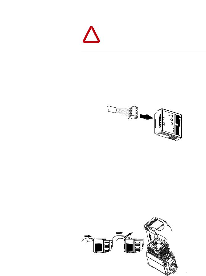
2. Make sure that the DeviceNet 10-pin Linear Plug is correctly wired (see Figure 3.9).
3. Locate the DeviceNet connector on the bottom of the module.
4. Insert the plug into the DeviceNet connector.
Figure 3.10
Installing the Drop Line
READY
FAULT
COMM
Removing Communication Module
From a Drive
If you need to reconfigure the Communication Module DIP switches, you must remove the Communication Module from the drive.
1.Remove the DeviceNet plug from the Communication Module.
2.Press in on the module’s latch and then push away and up.
3.Grasp the module and pull straight up. Avoid bending or twisting the contact pins located underneath the center portion of the module.
Figure 3.11
Removing the Communication Module
Publication 0160-5.18 - June 2003

Chapter 4
Modes of Operation
|
This chapter contains information about: |
|
|
• Powering up the drive with an installed 160-DN2 DeviceNet |
|
|
|
communication module. |
|
• Understanding the module’s modes of operation. |
|
|
Before you apply power, review the Safety Precautions on Preface |
|
|
page P-3. |
|
Powering Up the Drive |
After you have installed the 160-DN2 module, apply power to the |
|
|
drive and to the Network. The COMM LED should flash green or turn |
|
|
solid green. If it does not, refer to Chapter 7, Troubleshooting. |
|
Modes of Operation |
The 160-DN2 module operating modes are: |
|
|
• Power-up reset mode |
|
|
• |
Run mode |
|
• |
Error mode |
Power-up Reset Mode
During power-up or reset, the COMM LED is off.
The 160-DN2 module follows this sequence of operation:
1.When power-up occurs, the COMM LED flashes green for 1/4 second, red for 1/4 second, and then goes blank while the 160DN2 module finishes its initialization.
2.Performs power-up initialization.
3.Reads and stores the DIP switch settings.
4.Performs a duplicate node address check to verify that another node is not assigned the same DeviceNet address as the 160-DN2 module.
If the power-up or reset is successful, the 160-DN2 module enters the
Run mode and the COMM LED flashes green or turns solid green.
Publication 0160-5.18 - June 2003

4-2 |
Modes of Operation |
|
Modes of Operation (Continued) |
Power-up Reset Mode (Continued) |
|
|
|
If the power up or reset sequence fails, the COMM LED will turn |
|
|
solid red and the 160-DN2 module will enter the Error mode (see |
|
|
heading below for more information). |
Table 4.A COMM LED State During Power-up Reset Mode
COMM LED State |
Description |
|
|
Flashes Green 1/4 second, |
Occurs when power is applied to module. |
Red 1/4 second, |
|
then goes blank |
|
|
|
Blank |
Power-up initialization is taking place. |
|
|
Solid Red |
160-DN2 module is in Error mode. Indicates failed |
|
initialization, duplicate node address or incorrect baud rate. |
|
|
Solid Green |
160-DN2 module is in the Run mode. |
|
|
Run Mode
After a successful power-up or reset, the 160-DN2 module enters the run mode and operates as a slave device to a master device. In run mode, the module:
•Accepts messages from the master on the DeviceNet network.
•Monitors DeviceNet incoming power.
If an error is detected, the 160-DN2 module will enter the Error mode (see heading below for more information).
Error Mode
If the 160-DN2 module detects an error, the COMM LED is affected.
Errors are critical or noncritical, and are summarized below.
Table 4.B COMM LED State During Error Mode
COMM LED State |
Error Type |
Description |
|
|
|
|
|
|
|
Power-up initialization failure. |
|
Solid Red |
Critical |
|
|
Duplicate node address detected. |
|||
(not recoverable) |
|||
|
|
||
|
|
Incorrect baud rate. |
|
|
|
|
|
Flashing Red |
Non-Critical |
I/O connection timed out. |
|
(recoverable) |
|||
|
|
||
|
|
|
|
Off |
Non-Critical |
DeviceNet power lost. |
|
(recoverable) |
|||
|
|
||
|
|
|
See Chapter 7, Troubleshooting for details in the troubleshooting chart on how to recover from an error.
Publication 0160-5.18 - June 2003

Chapter 5
DeviceNet Parameter Descriptions
|
This chapter contains: |
|
• a description of DeviceNet parameters |
|
• the definition of Electronic Data Sheet (EDS) files |
|
• Bulletin 160 SSC Interface parameters |
|
• brief description of Bulletin 160 parameters |
|
Important: This chapter describes the parameter set for a Series C |
|
Bulletin 160. If you are using a Series A or Series B Bulletin 160, not |
|
all the parameters listed in this manual may apply to that drive. When |
|
using a Series A Bulletin 160, please refer to the Bulletin 160 SSC |
|
User Manual, Publication 0160-5.0. When using a Series B Bulletin |
|
160, please refer to the Bulletin 160 SSC User Manual, Publication |
|
0160-5.9. |
DeviceNet Parameters |
The 160-DN2 communication module contains a set of parameters |
|
that define how the module will interact with the Bulletin 160 SSC |
|
drive and the DeviceNet network. These parameters may be used to |
|
set the module’s address, baud rate, and I/O data format. Parameters |
|
may also be read to attain status from the module. |
Electronic Data Sheet (EDS) Files |
EDS files are specially formatted ASCII files that provide all of the |
|
information necessary for a configuration tool such as RSNetWorx |
|
for DeviceNet to access and alter the parameters of a device. The EDS |
|
file contains information on the number of parameters in a device and |
|
how those parameters are grouped. Additionally, the EDS file |
|
contains information about each parameter such as parameter min, |
|
max, and default values, parameter data format and scaling, and the |
|
parameter name and units. |
Parameters and EDS File |
You select an EDS file for the Bulletin 160 drive using a software |
|
application such as RSNetWorx for DeviceNet. (See Chapter 6, Using |
|
160-DN2 with DeviceNet Scanner, for instructions to select an |
|
appropriate EDS file.) An EDS file defines all the parameters in the |
|
Bulletin 160 drive and the 160-DN2 module, and creates a public |
|
interface to the drive on the DeviceNet network. Configuration tools |
|
such as RSNetWorx for DeviceNet use EDS files to present you with |
|
parameters that enable you to configure the 160 SSC drive via |
|
DeviceNet by changing values associated with individual parameters. |
Publication 0160-5.18 - June 2003
5-2 |
DeviceNet Parameter Descriptions |
Parameters and EDS File (Continued)
Parameter values may be read or written via DeviceNet. Writing a value to a parameter may configure drive operations such as acceleration or deceleration rates. Writing a value to a parameter may also configure DeviceNet operations such as which input or output assemblies are to be used for polled I/O communications with a master. Reading a parameter value gives you status information.
Bulletin 160 SSC Interface |
This parameter set contains all of the parameters described in the |
|
Bulletin 160 SSC User Manual, plus a few extra parameters to configure |
|
the operation of the 160-DN2 module on the DeviceNet network. |
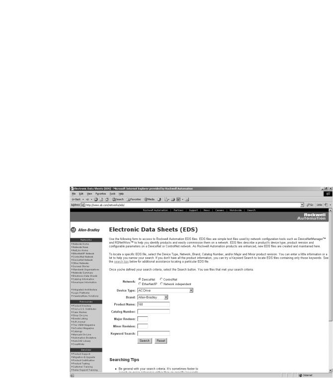
Locating EDS Files on the Internet |
Bulletin 160 SSC drives are available in Analog Signal Follower and |
|
Preset Speed models. Each model supports a slightly different set of |
|
parameters. (In general, the Preset Speed model contains extra |
|
parameters for setting up preset speeds.) Accordingly, each drive |
|
model uses an EDS file specific to that model. |
|
You can find the EDS file for your drive at http://www.ab.com/ |
|
networks/eds. Select the search criteria for the EDS file to be the |
|
same as that shown in the screen below. |
After the EDS file list appears, find your specific drive in the Product
Name column. Then, in the Brand column of that row click on the
Allen-Bradley Company link to access the EDS file for downloading.
Important: Use the correct EDS file for your specific drive model, horsepower, and voltage. If an incorrect EDS file is used, you may not be able to set up the drive with the configuration tool.
Publication 0160-5.18 - June 2003
Loading...