


 Loading...
1391-DES Digital
AC Servo Drive
User Manual

Important User Information
Because of the variety of uses for this equipment and because of the differences between this solid-state equipment and electromechanical equipment, the user of and those responsible for applying this equipment must satisfy themselves as to the acceptability of each application and use of the equipment. In no event will Allen-Bradley Company be responsible or liable for indirect or consequential damages resulting from the use or application of this equipment.
The illustrations shown in this manual are intended solely to illustrate the text of this manual. Because of the many variables and requirements associated with any particular installation, the Allen-Bradley Company cannot assume responsibility or liability for actual use based upon the illustrative uses and applications.
No patent liability is assumed by Allen-Bradley Company with respect to use of information, circuits or equipment described in this text.
Reproduction of the content of this manual, in whole or in part, without written permission of the Allen-Bradley Company is prohibited.
This information in this manual is organized in numbered chapters. Read each chapter in sequence and perform procedures when you are instructed to do so. Do not proceed to the next chapter until you have completed all procedures.
ATTENTION: Identifies information about practices or
!circumstances that can lead to personal injury or death, property damage or economic loss.
Attentions help you:
•identify a hazard
•avoid the hazard
•recognize the consequences
IMPORTANT: Identifies information that is especially important for successful application and understanding of the product.

Summary of Changes
Summary of Changes
Summary of Manual Changes This release of the 1391-DES User Manual contains some new and updated information. The new and updated information is summarized in the table below. For further information, refer to the page numbers provided.
Description of New or Updated Information |
Page |
Type |
|
|
|
Linear Accel/Decel information added |
1-4 |
New |
|
|
|
Speed Regulation specification added |
2-1 |
New |
|
|
|
Torque Plus Motor, Gearbox & Cable info |
3-4, 7, 8 |
New |
|
|
|
Important statement added to TB1 |
5-1 |
New |
|
|
|
Bus voltage info added to shunt resistor |
5-4 |
New |
|
|
|
Important statement added |
5-7 |
Clarification |
|
|
|
Parameter 69 name change |
6-14 |
Update |
|
|
|
Parameter 170 maximum value updated |
6-18 |
Update |
|
|
|
Parameter 199 updated |
6-20 |
Update |
|
|
|
Encoder Wiring |
7-5 |
Clarification |
|
|
|
Torque Plus info added to step 11 |
8-3 |
New |
|
|
|
Torque Plus info added (steps 30, 31) |
8-7 |
New |
|
|
|
Figure 8.1 updated |
8-10 |
Update |
|
|
|
Linear Accel/Decel information added |
8-11 |
New |
|
|
|
Torque Plus data added |
9-3 |
New |
|
|
|
#4 added to Auto Tune Fault |
11-7 |
Update |
|
|
|
TP50 description updated |
11-10 |
Update |
|
|
|
Enclosure items list |
A-3 |
New |
|
|
|
Interconnect drawings updated & added |
App. B |
Update |
|
|
|
1-4

Chapter
Introduction
Manual Objectives |
This manual is meant to guide the interface, installation, programming and |
|
troubleshooting of a 1391-DES Digital AC Servo Drive. The contents are |
|
arranged in order from a general description of the drive to troubleshooting |
|
and maintenance. To assure successful installation and operation, the |
|
material presented must be thoroughly read and understood before |
|
proceeding. Particular attention must be directed to the Attention and |
|
Important statements contained within. |
Important Information about this Manual
This manual has been prepared primarily to support this product in a single drive application. It is a standard document that is intended to help the user understand the individual operating characteristics and limitations of this equipment including hazards associated with installation, programming and maintenance procedures. Note the following points:
•This equipment has been designed to meet the requirements of a component drive in an integrated drive system.
•While the potential hazards associated with the drive remain the same when used in a system environment, it must be noted that special considerations are to be given to characteristics of other peripheral solid-state control equipment and the cumulative impact on safety.
•Manufacturers and engineering groups responsible for specification or design of electrical control equipment must refer to applicable industry standards and codes for specific safety guidelines and interface requirements.
•In the actual factory environment, the user is responsible to ensure compliance with applicable machine and operator safety codes or regulations which are beyond the scope and purpose of this document.
1-5

Chapter 1
Introduction
General Precautions |
In addition to the precautions listed throughout this manual, the following |
|
|
statements which are general to the drive must be read and understood. |
|
|
|
|
|
! |
ATTENTION: Only personnel familiar with the 1391-DES |
|
Digital Servo Drive and associated machinery should plan or |
|
|
implement the installation, start-up and subsequent maintenance |
|
|
|
|
|
|
of the drive. Failure to comply may result in personal injury |
|
|
and/or equipment damage. |
|
! |
ATTENTION: An incorrectly applied or installed drive can |
|
result in component damage or a reduction in product life. |
|
|
Wiring or application errors, such as, undersizing the motor, |
|
|
|
|
|
|
incorrect or inadequate AC supply, or excessive ambient |
|
|
temperatures may result in malfunction of the drive. |
|
! |
ATTENTION: This drive contains ESD (Electrostatic |
|
Discharge) sensitive parts and assemblies. Static control |
|
|
precautions are required when installing, testing, servicing or |
|
|
|
|
|
|
repairing this assembly. Component damage may result if ESD |
|
|
control procedures are not followed. If you are not familiar with |
|
|
static control procedures, reference Allen-Bradley publication |
|
|
8000-4.5.2, Guarding Against Electrostatic Damage or any |
|
|
other applicable ESD Protection Handbook. |
|
|
|
|
Certification Notice: In order to maintain UL listing on Allen-Bradley |
|
|
1391-DES Digital Servo Drives, the user must provide power from a 1391 |
|
|
Isolation Transformer. Use of any other transformer voids the UL listing. |
|
|
The user is responsible for providing motor overload protection in |
|
|
accordance with the National Electrical Code (NEC), and any other local |
|
|
codes that may apply. |
|
Drive Description |
The 1391-DES Pulse Width Modulated Digital Servo Drive is a digital and |
|
|
programmable single axis, AC servo drive. It has been packaged to require |
|
|
a minimum amount of panel space while containing, as standard, a number |
|
of features required by the machine tool and automated equipment industries.
The 1391-DES allows Allen-Bradley 1326 AC servomotors to be operated from 33% to 50% over their rated speed. This can help achieve greater precision, a finer finished product and increased production from existing machinery.
1-6

Chapter 1
Introduction
|
The 1391-DES is generally used with computer aided, closed loop |
|
positioning systems such as Allen-Bradley ªSº Class or IMC products. |
|
These systems control the position and linear or rotary motion of various |
|
machine members on an automated machine. To enhance system reliability, |
|
the 1391-DES has an encoder output (AQB) that produces four channels of |
|
2048, 1024, 512 or 256 lines and two marker pulses per motor revolution |
|
which feeds position information to the position controller. |
|
All components are mounted in an open framed package with a slide-on |
|
front cover. The drive is intended to be panel mounted in an enclosure and |
|
ventilated with filtered and/or cooled air. An internal fan is included to |
|
circulate air over the power heat sink. |
|
The 1391-DES converts a three-phase, 50/60 Hz input, to a variable AC |
|
voltage with controlled phase, amplitude and frequency. The output which |
|
is proportional to a user supplied analog command, regulates the speed |
|
and/or current (torque) of a 1326 permanent magnet AC servomotor. The |
|
drive is available in ratings of 15, 22.5 and 45A RMS with all package |
|
sizes being identical. A 1391 Transformer, 1326 AC Servomotor and 1326 |
|
Cables complete the servo system. |
Standard Features |
The 1391-DES contains a number of standard features required in a typical |
|
automated machine servo system. |
|
• Input protected against transient voltage. |
|
• A power line/DB contactor which opens the AC line to the drive and |
|
inserts a shunt regulator resistor across the DC bus whenever the |
|
contactor is de-energized. |
|
• An integral circuit breaker which will open all three AC line leads in the |
|
event of a short circuit condition in the power circuitry. |
|
• A standard 300V DC power bus supply that includes an integral shunt |
|
regulator. |
|
• A shunt regulator resistor to dissipate the energy generated by the motor |
|
during regenerative braking. |
|
• Prompted startup procedure to shorten setup time. |
|
• Two line LCD display and programming panel. |
|
• Patented current control implementation. |
|
• Torque feedforward differential input. |
|
• Microprocessor based logic boards that can be quickly removed and |
|
easily interchanged for troubleshooting and diagnostics. |
|
• Three drive ratings that are in the same physical package and have |
|
identical mounting dimensions. |
|
• True vector control. |
|
• Up to 600 feet (183 meters) between drive and motor. |
1-7

Chapter 1
Introduction
Options/Modifications |
The 1391-DES contains most functions needed in a servo system. |
The following are selectable at the user's option:
•Contactor Auxiliary Switch
Two N.O. (normally open) contacts are mounted on the main power contactor and wired to the power terminal block. These contacts can be used in a motor brake control circuit or as an indicator that the contactor has closed.
•Current or Torque Amplifier Operation
When the velocity loop is being closed as part of the position control system, the drive can be configured to operate as a current or torque amplifier by selection on the programming panel.
•External Shunt Regulator Resistor
On 15 and 22.5A drives an internal power resistor that is part of the DC bus voltage shunt regulator can dissipate 162 watts continuous power. Some applications such as an overhauling load have excessive regenerative energy to dissipate. For these applications, an external shunt regulator resistor rated at 386 watts continuous can be supplied for user mounting on 22.5A drives. This is selectable by removing the jumper on TB5 and using an external resistor. The shunt has integral fusing accessible from the outside of 15 and 22.5A drives. The 45A drive has an externally mounted resistor and fuse.
Important: An external shunt regulator resistor is included as standard equipment on 45A units. An additional unit is not required.
•Tach Output
A voltage equal to 1.2V DC/1000 RPM is available at TB2.
•Torque or Current Monitor
A voltage equal to 3.0V DC=100% scaled current is available at TB2.
•Anti-Backlash
Anti-backlash control can be implemented with several software parameters and an additional instruction manual. Contact your local Allen-Bradley Sales Office for details.
•Linear Accel/Decel
Linear accel/decel can be set using the CR-APG-001 Control Module. This module provides a manually generated trapezoidal velocity profile for up to four preset speeds.
Important: The 1391-DES contains one accel/decel rate which can be used if accel/decel times will be the same.
Drive Layout |
Figure 1.1 provides an exterior view of the 1391-DES AC Servo Drive, |
|
showing accessibility of various components. |
1-8
Chapter 1
Introduction
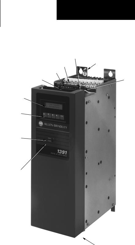
Figure 1.1
1391-DES Digital AC Servo Drive
Duty Cycle Selector Switch
Ground Stud
TB5 ± Power Connections
TB4 ± Control Signals
Circuit Breaker |
Fuses |
2 Line, 16 Character
LCD Display
5 Button Keypad used for Programming
Status LED
- Flashes green when no faults are present and the bus is low.
- Steady green when no faults are present and bus voltage is OK.
-Flashes red when a fault has occurred.
Enable LED
-Steady green when Enable input is closed at TB2-9 & 10.
-Not illuminated when Enable input is open.
TB2 ± Interface Signals
TB3 ± A Quad B Encoder Output Signals
1-9

Chapter 1
Introduction
End of Chapter
1-10

Chapter
Specifications
Chapter Objectives |
Chapter two contains the electrical and environmental specifications for the |
|||
|
1391-DES. Dimensions are provided in Appendix A. |
|
||
Drive Specifications |
The general specifications of the 1391-DES are provided in the listing |
|||
|
below. The specifications are divided when necessary for the various drive |
|||
|
ratings. |
|
|
|
|
Specific Drive Ratings |
1391-DES15 |
1391-DES22 |
1391-DES45 |
|
Nominal Bus Voltage |
300V DC |
300V DC |
300V DC |
|
Continuous Current (RMS) |
15A |
22.5A |
45A |
|
Peak Current (RMS) |
30A |
45A |
90A |
|
Continuous Power Output |
5.0 kW |
7.5 kW |
15.0 kW |
|
Peak Power Output |
10.0 kW |
15.0 kW |
30.0 kW |
|
Input Circuit Breaker Rating |
17A RMS |
26A RMS |
38A RMS |
|
Circuit Breaker Interrupt Rating |
|
|
|
|
(Symmetrical Amperes) |
1300A |
1300A |
1300A |
|
Unit Weight in lbs. (kg) |
22 (9.97) |
28 (12.69) |
34 (15.40) |
|
All Drive Ratings |
|
|
|
|
Static Gain (A/RMS) |
1.5 x Rated Motor Current / rpm (typical) |
|
|
|
Form Factor |
1.03 or less |
|
|
|
Peak Current Limit Adjust |
20 to 300% of Rated Motor Current or 2 x Continuous Rating of |
||
|
|
Drive (max.), whichever achieves Drive Peak Current Rating first |
||
|
Drive Efficiency |
85% (Minimum at Rated Load) |
|
|
|
Power Factor |
95% Minimum |
|
|
|
Modulation Frequency |
2500 Hz ±10% |
|
|
|
Drift (Referred to Tach) |
0.07 rpm /Degrees C. Maximum |
|
|
|
Speed Regulation |
0 to 0.05% of Maximum Motor Speed with 95% Load Change |
||
|
Ambient Temperature |
0 to 60° C (32 to 140° F) |
|
|
|
Storage Temperature |
0 to 65° C (32 to 149° F) |
|
|
|
Input Voltage (from Transformer) |
Power: 230V AC +10%/±15%, Three-Phase, 50/60 Hz ±3 Hz |
||
|
|
Control: 36V AC, Single-Phase |
|
|
|
Transformer Input Tolerance |
+10%, ±15% |
|
|
|
Relative Humidity |
5 to 95% Non-Condensing |
|
|
|
Deadband |
Zero |
|
|
|
Altitude |
1000 meters (3300 feet) |
|
|
|
Integral Fan Output |
50 CFM (Unloaded) |
|
|
|
Max. RMS Short Circuit Current |
1300A (Symmetrical Amperes) |
|
|
|
Certifications |
UL Listed - File No. E59272, CSA Certified - File No. LR32334-548, |
||
Specifications are for reference only and are subject to change without notice.
2-1
Chapter 2
Specifications
Environmental Specifications The 1391-DES must be mounted in an enclosure that is clean, dry and ventilated by filtered or cooled air. Enclosures vented with ambient air must have appropriate filtering to protect against contamination caused by oils, coolants, dust, condensation etc. The ambient air temperature must be kept between 0 to 60° C (32 to 140° F) and the humidity between 5 and 95%, non-condensing.
The 1391-DES is equipped with an integral cooling fan. The general flow of air through the unit must be maintained by following the recommended spacing guidelines found in Chapter 7. The 1391-DES can operate at elevations to 3300 feet (1000 meters) without derating, however, the current rating must be derated by 3% for each additional 1000 feet (305 meters) up to 10,000 feet (3050 meters). Consult with your local Allen-Bradley Sales Representative prior to operation over 10,000 feet (3050 meters).
Drive Power Dissipation |
The 1391-DES dissipation characteristics are approximated in Table 2.A. |
|||||
|
Table 2.A |
|
|
|
|
|
|
Drive Power Dissipation |
|
|
|
||
|
|
|
|
|
|
|
|
|
Rated Power Output |
1391-DES15 |
1391-DES22 |
1391-DES45 |
|
|
|
(%) |
(watts) |
(watts) |
(watts) |
|
|
|
20 |
38 |
55 |
104 |
|
|
|
40 |
76 |
110 |
208 |
|
|
|
60 |
114 |
165 |
312 |
|
|
|
80 |
152 |
220 |
416 |
|
|
|
100 |
190 |
275 |
520 |
|
Transformer Power Dissipation The power dissipation characteristics of the 1391 Isolation Transformer are shown in Table 2.B.
Table 2.B
1391 Isolation Transformer Power Dissipation
Rated Power Output |
1.5kVA |
3.5kVA |
5.0kVA |
10.0kVA |
12.5kVA |
15.0kVA |
(%) |
(watts) |
(watts) |
(watts) |
(watts) |
(watts) |
(watts) |
|
|
|
|
|
|
|
20 |
13 |
35 |
50 |
100 |
125 |
150 |
40 |
25 |
70 |
100 |
200 |
250 |
300 |
60 |
38 |
105 |
150 |
300 |
375 |
450 |
80 |
50 |
140 |
200 |
400 |
500 |
600 |
100 |
60 |
175 |
250 |
500 |
625 |
750 |
Important: Power Dissipation figures shown are for use in calculating cumulative system heat dissipation to ensure ambient temperature inside enclosure does not exceed 60° C (140° F).
2-2

Chapter
Receiving, Unpacking and Inspection
Chapter Objectives |
Chapter 3 provides the information needed to unpack, properly inspect and |
|
if necessary, store the 1391-DES and related equipment. The section |
|
entitled Inspection provides a complete explanation of the 1391-DES |
|
catalog numbering system. |
Receiving |
It is the responsibility of the user to thoroughly inspect the equipment |
|
before accepting the shipment from the freight company. Check the item(s) |
|
received against the purchase order. If any items are obviously damaged, it |
|
is the responsibility of the user not to accept delivery until the freight agent |
|
has noted the damage on the freight bill. Should any concealed damage be |
|
found during unpacking, it is again the responsibility of the user to notify |
|
the freight agent. The shipping container must be left intact and the freight |
|
agent should be requested to make a visual inspection of the equipment. |
Unpacking |
Remove all packing material, wedges, or braces from within and around |
|
the drive. Remove all packing material from the cooling fans, heat sink etc. |
|
Important: Before the installation and start-up of the drive, a general |
|
inspection of mechanical integrity (i.e. loose parts, wires, connections, |
|
packing materials, etc.) must be made. |
Inspection |
After unpacking, check the item(s) nameplate catalog number against the |
|
purchase order. An explanation of the catalog numbering system is |
|
included on the following pages as an aid for nameplate interpretation. |
Storing |
The drive should remain in its shipping container prior to installation. If the |
|
equipment is not to be used for a period of time, it must be stored |
|
according to the following instructions: |
|
• Store in a clean, dry location. |
|
• Store within an ambient temperature range of 0 to 65° C (32 to 149° F). |
|
• Store within a relative humidity range of 5% to 95%, non-condensing. |
|
• Do not store equipment where it could be exposed to a corrosive |
|
atmosphere. |
|
• Do not store equipment in a construction area. |
3-1

Chapter 3
Receiving, Unpacking and Inspection
|
|
|
|
|
|
|
|
|
|
Isolation Transformer |
|
|
|
|
|
||||||
1391 |
± |
|
T |
015 |
|
|
|
|
D |
|
|
|
T |
||||||||
First Position |
|
|
|
Second Position |
|
Third Position |
|
|
Fourth Position |
|
|
Fifth Position |
|||||||||
|
|
|
|
|
|
||||||||||||||||
Bulletin |
|
|
|
|
|
|
|
|
|
|
|
|
Primary Voltage |
|
|
Secondary |
|||||
Number |
|
|
|
Type |
|
|
|
|
kVA Rating |
|
& Frequency |
|
|
Voltage |
|||||||
|
|
|
|
Letter |
Description |
|
|
Number |
kVA |
|
|
Letter |
Description |
|
|
Letter |
Description |
||||
|
|
|
|
|
|
|
|
|
|
|
|
|
|
|
|
|
|
|
|
|
|
|
|
|
|
T |
Transformer |
|
015 |
1.5 |
|
|
|
D |
240/480V AC, Three- |
|
|
T |
230V AC, three-phase |
||||
|
|
|
|
|
Open Core |
|
035 |
3.5 |
|
|
|
|
Phase, 60 Hz |
|
|
|
and four 36V AC, |
||||
|
|
|
|
|
and Coil |
|
050 |
5.0 |
|
|
|
E |
240/380/415/480V AC, |
|
|
|
single-phase |
||||
|
|
|
|
|
|
|
|
100 |
10.0 |
|
|
|
|
|
C.T.windings |
||||||
|
|
|
|
|
|
|
|
|
|
|
Three-Phase, 50/60 Hz |
|
|
|
|||||||
|
|
|
|
|
|
|
|
125 |
12.5 |
|
|
|
|
|
|
|
|
||||
|
|
|
|
|
|
|
|
|
|
N |
208/230/460/575V AC, |
|
|
|
|
|
|||||
|
|
|
|
|
|
|
|
150 |
15.0 |
|
|
|
|
|
|
|
|||||
|
|
|
|
|
|
|
|
|
|
|
Three-Phase, 60 Hz |
|
|
|
|
|
|||||
|
|
|
|
|
|
|
|
|
|
|
|
|
|
|
|
|
|
|
|
||
|
|
|
|
|
|
|
|
|
|
|
|
|
|
|
|
|
|
|
|
||
NEMA Type 1 Transformer Enclosure Kit
1391 |
± |
TA2 |
||
Bulletin |
|
|
Accessory |
|
|
||||
Number |
|
|
Module |
|
|
|
|
Letter |
Description |
|
|
|
|
|
|
|
|
TA2 |
Fits all kVA ratings on 1386, 1388, |
|
|
|
|
1389 and 1391 Isolation Transformers. |
|
External Shunt Regulator Resistor |
||||||||
1391 |
± |
MOD |
± |
SR22A |
|||||
First Position |
|
|
|
Second Position |
|
|
Third Position |
||
|
|
|
|
|
|||||
Bulletin |
|
|
|
Type |
|
|
|
|
|
Number |
|
|
|
|
|
|
Description |
||
|
|
|
|
Code |
Description |
|
|
Code |
Description |
|
|
|
|
|
|
|
|
|
|
|
|
|
|
|
|
|
|
SR22A |
Shunt Regulator Resistor for 22.5A Drive |
|
|
|
|
MOD |
Modifica- |
|
|
||
|
|
|
|
|
tion Kit |
|
|
SR45A |
Shunt Regulator Resistor for 45A Drive 1 |
1 Drive comes equipped with this resistor as standard. Catalog number is provided if spare or replacement is required,
3-2

Chapter 3
Receiving, Unpacking and Inspection
|
|
|
|
|
|
Bulletin 1391-DES Drive |
|
|
|
|
|
|
|
|
|
|
|
||
1391 |
± |
|
DES15 |
± |
|
|
DI |
± |
|
AQB |
± |
|
A |
||||||
First Position |
|
Second Position |
|
|
Third Position |
|
|
Fourth Position |
|
|
Fifth Position |
||||||||
|
|
|
|
||||||||||||||||
Bulletin |
|
Configuration/ |
|
|
User |
|
|
|
Output |
|
|
|
|
|
|
||||
Number |
|
Current Rating |
|
|
Interface |
|
|
Configuration |
|
|
Options |
||||||||
|
|
Code |
Description |
|
|
Code |
Description |
|
|
Code |
Description |
|
|
Letter |
Description |
||||
|
|
|
|
|
|
|
|
|
|
|
|
|
|
|
|
|
|
|
|
|
|
DES15 |
15A Continuous Current |
|
|
DI |
Includes Integral |
|
|
AQB |
Encoder Output ± |
|
|
A |
24V DC M contactor |
||||
|
|
DES22 |
22.5A Continuous Current |
|
|
Display |
|
|
|
|
2048, 1024, 512, |
|
|
|
|
coil voltage instead of |
|||
|
|
|
|
|
|
|
|
|
256 selectable |
|
|
|
|
115V AC (available |
|||||
|
|
DES45 |
45A Continuous Current |
|
|
|
|
|
|
|
|
|
|
|
|
||||
|
|
|
|
|
|
|
|
|
|
pulses/motor |
|
|
|
|
on 22A drives only) |
||||
|
|
|
|
|
|
|
|
|
|
|
|
|
|
|
|
|
|||
|
|
|
|
|
|
|
|
|
|
|
|
|
revolution |
|
|
Blank |
115V AC M contactor |
||
|
|
|
|
|
|
|
|
|
|
|
|
|
|
|
|
||||
|
|
|
|
|
|
|
|
|
|
|
|
|
|
|
|
|
|
coil voltage |
|
|
|
|
1326AB Servomotor |
|
|
|
|
1326 |
A |
B ± A |
3 |
E |
± |
11 ± |
A4 |
First Position |
|
Second Position |
|
Third Position |
|
Fourth Position |
|
Fifth Position |
|||||
Bulletin |
|
Type |
|
|
|
|
|
|
|
|
|
Motor |
|
Number |
|
|
|
|
Design |
|
Series |
|
Length |
||||
|
|
Letter |
Description |
|
Description |
|
Description |
|
Description |
||||
|
|
|
|
|
|
|
|
|
|
|
|
|
|
|
|
A |
AC |
|
Factory |
|
Sequentially |
|
Sequentially |
||||
|
|
|
Servomotor |
|
use only |
|
lettered to |
|
numbered to |
||||
|
|
|
PM Type |
|
|
|
|
designate frame |
|
indicate stack |
|||
|
|
|
|
|
|
|
|
|
diameters. |
|
length within a |
||
|
|
|
|
|
|
|
|
|
|
|
|
given frame size. |
|
|
|
|
|
|
|
|
|
|
|
|
|
|
|
Sixth Position
Max. Op.
Speed 2
Letter RPM
B1600/2000
C2000/3000
E 3000/4000
G 5000/6000
Seventh Posi- |
Eighth Posi- |
tion |
tion |
Mounting & Shaft |
Standard |
Description |
Options |
Code Description
11NEMA Inch Combination Face/Flange with Keyway
21IEC Metric Flange with Keyway
Code Description |
Code Description |
A4.25º (108 mm)
B5.88º (149 mm)
C7.63º (194 mm)
A4 72 lb.-in. (8.1 N-m) Holding Brake w/90V DC Coil. A5 120 lb.-in. (13.6 N-m) Holding Brake w/90V DC Coil. A7 360 lb.-in. (40.7 N-m) Holding Brake w/90V DC Coil. K4 72 lb.-in. (8.1 N-m) Holding Brake w/24V DC Coil. K5 120 lb.-in. (13.6 N-m) Holding Brake w/24V DC Coil. K7 360 lb.-in. (40.7 N-m) Holding Brake w/24V DC Coil.
2 Ratings shown indicate the rated speed and speed capability of the motor with the 1391-DES (rated/w 1391-DES).
3-3

Chapter 3
Receiving, Unpacking and Inspection
|
|
|
|
|
|
|
|
|
|
|
1326AB Torque Plus Series Servomotor |
|
|
|
|
|
|
|
|
|
|||||||||
1326 |
|
|
AB |
± |
A |
4 |
|
30 |
|
|
|
|
E |
± |
|
|
|
21 |
|
± |
A4 |
||||||||
First Position |
|
Second Position |
|
|
Third Position |
|
|
Fourth Position |
|
|
Fifth Position |
|
|
Sixth Position |
|
|
|
Seventh Position |
|
|
Eighth Position |
||||||||
|
|
|
|
|
|
|
|
|
|||||||||||||||||||||
Bulletin |
|
|
|
|
|
|
|
|
|
|
|
|
|
|
Motor |
|
|
Max. Operating |
|
|
|
Mounting & Shaft |
|
|
Standard |
||||
Number |
|
Type |
|
|
|
Voltage |
|
|
Series |
|
|
Length |
|
|
Speed |
|
|
|
Description |
|
|
Options |
|||||||
|
|
Letter |
Description |
|
|
Code Rating |
|
|
Description |
|
|
Description |
|
|
Letter |
Rated/1391-DES |
|
Code |
Description |
|
|
|
|||||||
|
|
|
|
|
|
|
|
|
|
|
|
|
|
|
|
|
|
|
|
|
|
|
|
|
|
|
|
|
|
|
|
AB |
Ferrite AC |
|
|
A |
230V AC |
|
|
Sequentially |
|
|
Sequentially |
|
|
B |
1600/2000 rpm |
21 |
IEC Metric |
|
|
|
|||||||
|
|
|
Servomo- |
|
|
|
|
|
|
|
lettered to |
|
|
numbered to |
|
|
C |
2000/3000 rpm |
|
|
Flange with |
|
|
|
|||||
|
|
|
tor |
|
|
|
|
|
|
|
designate frame |
|
|
indicate stack |
|
|
E |
3000/4000 rpm |
|
|
Keyway |
|
|
|
|||||
|
|
|
|
|
|
|
|
|
|
|
diameters. |
|
|
length within a |
|
|
G |
5000/6000 rpm |
|
|
|
|
|
|
|
||||
|
|
|
|
|
|
|
|
|
|
|
|
|
|
|
given frame size. |
|
|
|
|
|
|
|
|
|
|
|
|
|
|
|
|
|
|
|
|
|
|
|
|
|
|
|
|
|
|
|
|
|
|
|
|
|
|
|
|
|
|||
Code Description
4115 mm
5166 mm
7215 mm
Code Description
A4 72 lb.-in. (8.1 N-m) Holding Brake w/90V DC Coil for 1326AB-A4 A5 120 lb.-in. (13.6 N-m) Holding Brake w/90V DC Coil for 1326AB-A5 A7 360 lb.-in. (40.7 N-m) Holding Brake w/90V DC Coil for 1326AB-A7 K4 72 lb.-in. (8.1 N-m) Holding Brake w/24V DC Coil for 1326AB-A4 K5 120 lb.-in. (13.6 N-m) Holding Brake w/24V DC Coil for 1326AB-A5 K7 360 lb.-in. (40.7 N-m) Holding Brake w/24V DC Coil for 1326AB-A7
|
Shaft Oil Seal Kit |
|
1326AB ± MOD ± SS |
V ± A |
1 |
First Position |
|
Second Position |
|
|
Third Position |
|
Fourth Position |
|
Fifth Position |
|
|
||||
Bulletin |
|
|
|
|
|
Shaft |
|
|
|
|
|
Motor |
|
|
|
Number |
|
Type |
|
|
|
Seal |
|
Material |
|
Series |
|
|
|||
|
|
Code |
Description |
|
|
|
|
Letter |
Description |
|
Letter |
Standard |
Torque Plus |
||
|
|
|
|
|
|
|
|
|
|
|
|
|
|
|
|
|
|
MOD |
Modifica- |
|
|
|
|
V |
Viton |
|
A |
Series A |
-A4 |
Use |
|
|
|
|
tion Kit |
|
|
|
|
|
|
|
|
B |
Series B |
-A5 |
Metric |
|
|
|
3 |
|
|
|
|
|
|
|
|
C |
Series C |
-A7 |
Only |
|
|
|
|
|
|
|
|
|
|
||||||
|
|
|
ªAº Series motors with brake must use 1326AB-MOD-SSV-A2. |
|
|
||||||||||
Sixth Position
Motor
Mounting 3
Number Description
1Std. Inch
2Metric
|
|
|
Brake Power Supply Rectifier |
|||||
1326 |
± MOD |
± |
|
BPS |
||||
Bulletin |
|
|
Type |
|
|
|
|
|
|
|
|
|
|
|
|
||
Number |
|
|
|
|
|
Description |
||
|
|
|
Code |
Description |
|
|
Code |
Description |
|
|
|
|
|
|
|
|
|
|
|
|
MOD |
Modifica- |
|
|
BPS |
Single-phase, full-wave, screw mount |
|
|
|
|
tion Kit |
|
|
|
rectifier. 115V AC input, for use with 90V DC |
4 |
|
|
|
|
|
|
|
brakes. 4 |
|
Up to 4 brakes per rectifier can be used. |
|||||||
3-4

Chapter 3
Receiving, Unpacking and Inspection
Motor Junction Box Kit 5
1326AB |
± MOD |
± |
|
RJAB |
|||||
First Position |
|
|
Second Position |
|
|
Third Position |
|||
|
|
||||||||
Bulletin |
|
|
Type |
|
|
|
Description |
||
Number |
|
|
|
|
|
||||
|
|
|
Code |
Description |
|
|
Code |
Description |
|
|
|
|
|
|
|
|
|
|
|
|
|
|
MOD |
Modifica- |
|
|
RJAB |
For all AB-A & B Series Motors |
|
|
|
|
|
tion Kit |
|
|
|
(A4 & A5 Torque Plus Motors) |
|
|
|
|
|
|
|
|
RJB |
For all AB-B4 & Cx Series Motors |
|
|
|
|
|
|
|
|
C |
(A7 Torque Plus Motors) |
|
|
|
|
|
|
|
|
|
|
|
5The motor comes standard with IP65 plug style connectors mounted radially to the motor. This kit allows the connectors to be brought out axially to the motor without further wiring. Kit includes Motor Junction Box and
Mounting Hardware.
|
|
|
Feedback Mounting Adapter Kit 6 |
|
|
|
|
|
|||
1326AB ± MOD |
± |
M4 |
± |
|
C1 |
||||||
First Position |
|
Second Position |
|
|
Third Position |
|
|
Fourth Position |
|||
|
|
|
|
||||||||
Bulletin |
|
|
|
|
|
Mounting Adapter |
|
|
Coupling Size |
||
Number |
|
Type |
|
|
|
Kit for . . . |
|
|
for . . . |
|
|
|
|
Code |
Description |
|
|
|
|
|
Code |
Motor Series |
|
|
|
|
|
|
|
|
|
|
|
|
|
|
|
MOD |
Modifica- |
|
|
|
|
|
C1 |
A, B, C (A4, A5, A7 Torque Plus) |
|
|
|
|
tion Kit |
|
|
|
|
|
Blank |
For M22, M23, M24, M25, M26 |
|
|
|
|
|
|
|
|
|
|
|||
|
|
|
|
|
|
|
|
|
|
|
|
Code Description
M4 A-B 845H/T Encoder for AB-A series motor (A4 Torque Plus)
M5 A-B 845H/T Encoder for AB-B series motor (A5 Torque Plus)
M6 A-B 845H/T Encoder for AB-C series motor (A7 Torque Plus)
M22 Type VC/VD 4.25º (108 mm) Resolver for AB-B series motor (A5 Torque Plus) M23 Type VC/VD 4.25º (108 mm) Resolver for AB-C series motor (A7 Torque Plus) M24 0.375º (9.5 mm) diameter heavy duty shaft extension adapter
M25 0.625º (15.9 mm) diameter heavy duty shaft extension for type VC/VD 4.25º (108 mm) resolver
M26 Foot mounting kit for M25
6All kits contain a feedback device mounting adapter and mounting hardware. M4, M5 and M6 include a motor to encoder coupling. M22 and M23 do not include a coupling since it is included with the resolver feedback device.
3-5

Chapter 3
Receiving, Unpacking and Inspection
|
|
|
|
|
Feedback Coupling 7 |
|
|||||||||
1326 |
± |
|
MOD |
± |
C1 |
|
|||||||||
First Position |
|
|
Second Position |
|
|
Third Position |
|
||||||||
|
|
|
|||||||||||||
Bulletin |
|
|
|
|
|
|
|
|
|
|
Coupling |
|
|||
Number |
|
|
Type |
|
|
|
|
|
|
Size |
|
||||
|
|
|
|
|
Code |
|
Description |
|
|
|
Code Size ± Motor Shaft to Encoder Shaft |
||||
|
|
|
|
|
MOD |
Modifica- |
|
|
C1 3/8º to 3/8º (9.5 mm to 9.5 mm) ± |
||||||
|
|
|
|
|
|
|
tion Kit |
|
|
Standard on all 1326AB Motors |
|||||
|
|
|
|
|
|
|
|
|
|
|
|
|
C2 1/4º to 3/8º (6.4 mm to 9.5 mm) |
||
7 The feedback coupling is included as standard with all Feedback Mounting Adapter Kits. |
|||||||||||||||
|
|
|
|
Resolver Feedback Package |
|
||||||||||
1326AB |
± MOD |
|
± |
|
VC |
|
|
1:1 |
|||||||
|
|
|
|
|
|
||||||||||
First Position |
|
Second Position |
|
Third Position |
|
Fourth Position |
|||||||||
Bulletin |
|
Type |
|
|
|
|
|
Resolver Feedback |
|
Gear Ratio |
|||||
Number |
|
|
|
|
|
|
Package |
|
|
Input:Resolver |
|||||
|
|
Code |
Description |
|
|
|
|
|
|
|
|
|
|||
|
|
|
|
|
|
|
|
|
|
|
|
|
|||
|
|
MOD |
Modifica- |
|
|
|
|
|
|
|
|
|
|||
|
|
|
tion Kit |
8 |
|
|
|
|
|
|
|
|
|
||
|
|
|
|
|
|
|
|
|
|
|
|
|
|||
Code Description |
|
|
|
|
|
|
Code |
Description |
|
|
|
||||
VC |
4.25º (108 mm) feedback package with cast |
|
housing and single or vernier (dual) format with |
|
receiver (Harowe 11BRW-300-F-58A or equivalent) |
|
type resolver(s) for use with A-B series 8200 CNC |
|
and IMC] 120, 121, 123. |
VD |
4.25º (108 mm) feedback package with cast |
|
housing and single or vernier (dual) format with |
|
transmitter (Harowe 11BRCX-300-C10/6 or |
|
equivalent) type resolver(s) for use with A-B series |
|
8600, MAX and IMC S Class controllers with a |
|
REC 4096 Board. |
1:1 Single device format ± 1 turn of the motor shaft to 1 turn of the resolver.
1:2 Single device format ± 1 turn of the motor shaft to 2 turns of the resolver.
1:2.5 Single device format ± 1 turn of the motor shaft to 2.5 turns of the resolver.
1:5 Single device format ± 1 turn of the motor shaft to 5 turns of the resolver.
255Absolute master/vernier format ± 1:1 input/master, 255:256 master/vernier for IMC 120, 121, 123 only.
256Absolute master/vernier format ± 1:1 input/master, 256:255 master/vernier for 8600 series and MAX, IMC S class controls with a REC 4096 Board.
424Absolute master/vernier format ± 1:1 input/master, 424:425 master/vernier for IMC 120, 121, 123 only.
425Absolute master/vernier format ± 1:1 input/master, 425:424 master/vernier for 8600 series and MAX, IMC S class controls with a REC 4096 Board.
800Absolute master/vernier format ± 1:1 input/master, 800:801 master/vernier for IMC 120, 121, 123 only.
801Absolute master/vernier format ± 1:1 input/master, 801:800 master/vernier for 8600 series controllers (is not applicable for use with MAX and IMC S Class controls)
8 Kit includes Resolver Feedback Package, mounting hardware and 3/8º to 3/8º (9.5 mm to 9.5 mm) resolver to motor mounting coupling.
3-6

Chapter 3
Receiving, Unpacking and Inspection
|
|
|
|
|
|
|
|
|
|
Power and Feedback Cables |
|
|
|
|
|
|
|
|
|||||
1326 |
|
± |
C |
|
|
P |
|
|
AB |
|
|
|
T |
15 |
|
||||||||
First Position |
|
Second Position |
|
Third Position |
|
Fourth Position |
|
Fifth Position |
|
Sixth Position |
|||||||||||||
|
|
|
|
|
|||||||||||||||||||
Bulletin |
|
Type |
|
|
|
Function |
|
Motor Size |
|
Power Track |
|
Cable |
|
||||||||||
Number |
|
|
|
|
|
Used On |
|
Cable |
|
|
|
Length |
|||||||||||
Code |
Description |
|
Code |
Description |
|
Letter |
Description |
|
Code |
Type |
|
Letter |
Description |
|
Code |
Description |
|||||||
|
|
|
|
|
|||||||||||||||||||
|
|
|
|
|
|
|
|
|
|
|
|
|
|
|
|
|
|
|
|
|
|
|
|
1326 |
Standard |
|
C |
Connector |
|
P |
Power Connection |
|
AB |
Series A & B (except |
|
T |
All Series, |
|
K |
Connector Kit |
|||||||
|
Cable |
|
|
|
& Cable |
|
|
|
|
|
1326AB-B4) |
|
|
|
used for |
|
|
(No Cable) |
|||||
1326ES 9 Extended |
|
|
|
Assembly |
|
|
|
|
C Series C & 1326AB-B4 |
|
|
|
high flex |
15 |
15' (4.6 m) |
||||||||
|
length cable |
|
CC |
Connector |
|
|
|
|
|
|
|
|
|
|
|
applications |
30 |
30' (9.1 m) |
|||||
|
|
|
F |
Commutation & |
|
U |
All Series |
|
Blank |
|
|
||||||||||||
|
used with |
|
|
|
on both |
|
|
|
Standard |
50 |
50' (15.2 m) |
||||||||||||
|
1391B-ES |
|
|
|
ends (for |
|
|
Feedback Connection |
|
|
|
|
|
|
|
|
Cable |
100 |
100' (30.4 m) |
||||
|
& |
|
|
|
|
use with |
|
E |
845H/T Encoder |
|
|
|
|
|
|
|
|
|
|
150 9 |
150' (45.7 m) |
||
|
1391-DES |
|
|
|
1391C-HB) |
|
V |
All 4.25º (108 mm) |
|
|
|
|
|
|
|
|
|
|
200 9 |
200' (61 m) |
|||
|
Only |
|
|
|
|
|
|
|
|
|
|
|
|
|
|
|
|
250 9 |
250' (76.2 m) |
||||
|
|
|
|
|
|
|
|
Resolver Packages |
|
|
|
|
|
|
|
|
|
|
|||||
|
|
|
|
|
|
|
|
|
|
|
|
|
|
|
|
|
|
|
|
300 9 |
300' (91.4 m) |
||
|
|
|
|
|
|
|
|
|
|
|
|
|
|
|
|
|
|
|
|
|
|||
9 The extended length option is only available for 1326-CFUxx, CPABxx and CPCxx cables and can only be used with 1391B-ES and 1391-DES drives.
|
|
Blower Mod Kit |
|
|
|
|
|
|
1326AB |
± |
MOD |
± |
|
G3 |
|||
First Position |
|
Second Position |
|
|
|
Third Position |
||
|
|
|||||||
Bulletin |
|
Type |
|
|
|
|
Description |
|
Number |
|
|
|
|
|
|||
|
|
Code |
Description |
|
|
|
Code |
Motor Series |
|
|
|
|
|
|
|
|
|
|
|
MOD |
Modifica- |
|
|
|
G3 |
Rear mounted blower for C |
|
|
|
tion Kit |
|
|
|
|
series motors |
|
|
|
|
|
|
|
G4 |
ªSaddleº type blower for C |
|
|
|
|
|
|
|
|
series motors with rear |
|
|
|
|
|
|
|
|
mounted encoders |
|
|
|
|
|
|
|
|
|
3-7

Chapter 3
Receiving, Unpacking and Inspection
|
|
|
|
|
|
|
|
Planetary Gearbox |
|
|
|
|
|
|
|
|
||||
1326AB ± |
PG |
|
|
A |
|
|
|
|
05 |
± |
|
LB |
± |
|
21 |
|||||
First Position |
|
Second Position |
|
Third Position |
|
|
|
Fourth Position |
|
|
Fifth Position |
|
Sixth Position |
|||||||
|
|
|
|
|
|
|
|
|||||||||||||
Bulletin |
|
Type |
|
Used on 1326AB |
|
Gear Ratio |
|
|
|
|
|
|
|
|
||||||
Number |
|
|
Motor Series |
|
|
|
(Motor Shaft:Output Shaft) |
|
Options |
|
Adapter |
|||||||||
|
|
Code |
Description |
|
Code |
Standard |
Torque Plus |
|
Code |
Description |
|
|
Code |
Description |
|
Code |
Description |
|||
|
|
|
|
|
|
|
|
|
|
|
|
|
|
|
|
|
|
|
|
|
|
|
PG |
Straight |
|
A |
Series A |
-A4 10 |
|
03 |
3:1 |
|
|
Blank |
No Options |
|
21 |
Metric |
|||
|
|
|
Planetary Gearbox |
|
B |
Series B |
-A5 10 |
05 |
5:1 |
|
|
LB |
Low Back- |
|
11 |
English |
||||
|
|
RP |
Right Angle |
|
C |
Series C |
-A7 10 |
10 |
10:1 |
|
|
|
lash Option |
|
|
|
|
|||
|
|
|
15 |
15:1 |
|
|
|
|
|
|
|
|||||||||
|
|
|
Planetary Gearbox |
|
|
|
|
|
20 |
20:1 |
|
|
|
|
|
|
|
|
||
|
|
|
|
|
|
|
|
|
|
|
|
|
|
|
|
|
|
|||
|
|
|
|
|
|
|
|
|
|
30 |
30:1 |
|
|
|
|
|
|
|
|
|
|
|
|
|
|
|
|
|
|
|
50 |
50:1 |
|
|
|
|
|
|
|
|
|
|
|
|
|
|
|
|
|
|
|
100 |
100:1 |
|
|
|
|
|
|
|
|
|
10 Use only -21 (Metric) style adapter gearboxes for -A4, -A5 Torque Plus Motors.
3-8

Table of Contents
Introduction |
Chapter 1 |
|
|
Manual Objectives . . . . . . . . . . . . . . . . . . . . . . . . . . . . . . . . . . . . . . . . . |
1-1 |
|
General Precautions . . . . . . . . . . . . . . . . . . . . . . . . . . . . . . . . . . . . . . . . |
1-2 |
|
Drive Description . . . . . . . . . . . . . . . . . . . . . . . . . . . . . . . . . . . . . . . . . . |
1-2 |
|
Standard Features . . . . . . . . . . . . . . . . . . . . . . . . . . . . . . . . . . . . . . . . . . |
1-3 |
|
Options/Modifications . . . . . . . . . . . . . . . . . . . . . . . . . . . . . . . . . . . . . . |
1-4 |
|
Drive Layout . . . . . . . . . . . . . . . . . . . . . . . . . . . . . . . . . . . . . . . . . . . . . |
1-4 |
Specifications |
Chapter 2 |
|
|
Chapter Objectives . . . . . . . . . . . . . . . . . . . . . . . . . . . . . . . . . . . . . . . . . |
2-1 |
|
Drive Specifications . . . . . . . . . . . . . . . . . . . . . . . . . . . . . . . . . . . . . . . . |
2-1 |
|
Environmental Specifications . . . . . . . . . . . . . . . . . . . . . . . . . . . . . . . . |
2-2 |
|
Drive Power Dissipation . . . . . . . . . . . . . . . . . . . . . . . . . . . . . . . . . . . . |
2-2 |
|
Transformer Power Dissipation . . . . . . . . . . . . . . . . . . . . . . . . . . . . . . . |
2-2 |
Receiving, Unpacking & Inspection Chapter 3 |
|
Chapter Objectives . . . . . . . . . . . . . . . . . . . . . . . . . . . . . . . . . . . . . . . . . |
3-1 |
Receiving . . . . . . . . . . . . . . . . . . . . . . . . . . . . . . . . . . . . . . . . . . . . . . . . |
3-1 |
Unpacking . . . . . . . . . . . . . . . . . . . . . . . . . . . . . . . . . . . . . . . . . . . . . . . |
3-1 |
Inspection . . . . . . . . . . . . . . . . . . . . . . . . . . . . . . . . . . . . . . . . . . . . . . . . |
3-1 |
Storing . . . . . . . . . . . . . . . . . . . . . . . . . . . . . . . . . . . . . . . . . . . . . . . . . . |
3-1 |
Description of Operation |
Chapter 4 |
|
|
Chapter Objectives . . . . . . . . . . . . . . . . . . . . . . . . . . . . . . . . . . . . . . . . . |
4-1 |
|
General . . . . . . . . . . . . . . . . . . . . . . . . . . . . . . . . . . . . . . . . . . . . . . . . . . |
4-1 |
|
300V DC Power Bus Supply . . . . . . . . . . . . . . . . . . . . . . . . . . . . . . . . . |
4-1 |
|
PWM Operation . . . . . . . . . . . . . . . . . . . . . . . . . . . . . . . . . . . . . . . . . . . |
4-1 |
|
Shunt Regulator Operation . . . . . . . . . . . . . . . . . . . . . . . . . . . . . . . . . . |
4-3 |
|
Logic Power Supply . . . . . . . . . . . . . . . . . . . . . . . . . . . . . . . . . . . . . . . |
4-3 |
|
Logic Control Boards . . . . . . . . . . . . . . . . . . . . . . . . . . . . . . . . . . . . . . |
4-3 |
|
Fault Monitoring and Detection . . . . . . . . . . . . . . . . . . . . . . . . . . . . . . . |
4-3 |
|
Microprocessor Control . . . . . . . . . . . . . . . . . . . . . . . . . . . . . . . . . . . . . |
4-5 |
|
Isolated Current Sensing . . . . . . . . . . . . . . . . . . . . . . . . . . . . . . . . . . . . |
4-5 |
|
Integral Circuit Breaker . . . . . . . . . . . . . . . . . . . . . . . . . . . . . . . . . . . . . |
4-5 |
|
Line/DB Contactor . . . . . . . . . . . . . . . . . . . . . . . . . . . . . . . . . . . . . . . . . |
4-5 |
|
Power Driver Board . . . . . . . . . . . . . . . . . . . . . . . . . . . . . . . . . . . . . . . . |
4-5 |
|
A Quad B Board . . . . . . . . . . . . . . . . . . . . . . . . . . . . . . . . . . . . . . . . . . |
4-5 |
|
Starting and Stopping . . . . . . . . . . . . . . . . . . . . . . . . . . . . . . . . . . . . . . |
4-5 |
|
Power-Up/Down Sequence . . . . . . . . . . . . . . . . . . . . . . . . . . . . . . . . . . |
4-7 |
Inputs, Outputs and Switch Settings Chapter 5
Chapter Objectives . . . . . . . . . . . . . . . . . . . . . . . . . . . . . . . . . . . . . . . . . 5-1
Inputs/Outputs . . . . . . . . . . . . . . . . . . . . . . . . . . . . . . . . . . . . . . . . . . . . 5-1
Switch Settings . . . . . . . . . . . . . . . . . . . . . . . . . . . . . . . . . . . . . . . . . . . 5-6
i
Table of Contents
Programming |
Chapter 6 |
|
|
Chapter Objectives . . . . . . . . . . . . . . . . . . . . . . . . . . . . . . . . . . . . . . . . . |
6-1 |
|
Display Description . . . . . . . . . . . . . . . . . . . . . . . . . . . . . . . . . . . . . . . . |
6-1 |
|
Keypad Description . . . . . . . . . . . . . . . . . . . . . . . . . . . . . . . . . . . . . . . . |
6-1 |
|
Parameter Levels . . . . . . . . . . . . . . . . . . . . . . . . . . . . . . . . . . . . . . . . . . |
6-3 |
|
Accessing Parameter Levels . . . . . . . . . . . . . . . . . . . . . . . . . . . . . . . . . |
6-6 |
|
Programming . . . . . . . . . . . . . . . . . . . . . . . . . . . . . . . . . . . . . . . . . . . . . |
6-7 |
|
Parameter Descriptions . . . . . . . . . . . . . . . . . . . . . . . . . . . . . . . . . . . . . |
6-8 |
Installation |
Chapter 7 |
|
|
Chapter Objectives . . . . . . . . . . . . . . . . . . . . . . . . . . . . . . . . . . . . . . . . . |
7-1 |
|
Mounting . . . . . . . . . . . . . . . . . . . . . . . . . . . . . . . . . . . . . . . . . . . . . . . . |
7-1 |
|
Wiring Recommendations . . . . . . . . . . . . . . . . . . . . . . . . . . . . . . . . . . . |
7-2 |
|
Wiring . . . . . . . . . . . . . . . . . . . . . . . . . . . . . . . . . . . . . . . . . . . . . . . . . . |
7-4 |
Start-Up |
Chapter 8 |
|
|
Chapter Objectives . . . . . . . . . . . . . . . . . . . . . . . . . . . . . . . . . . . . . . . . . |
8-1 |
|
Start-Up Procedure . . . . . . . . . . . . . . . . . . . . . . . . . . . . . . . . . . . . . . . . |
8-1 |
|
Linear Accel/Decel Control Module . . . . . . . . . . . . . . . . . . . . . . . . . . |
8-11 |
1326AB AC Servomotor |
Chapter 9 |
|
|
Chapter Objectives . . . . . . . . . . . . . . . . . . . . . . . . . . . . . . . . . . . . . . . . . |
9-1 |
|
Introduction . . . . . . . . . . . . . . . . . . . . . . . . . . . . . . . . . . . . . . . . . . . . . . |
9-1 |
|
Motor Options/Accessories . . . . . . . . . . . . . . . . . . . . . . . . . . . . . . . . . . |
9-3 |
Transformers and Shunt Regulators Chapter 10 |
|
|
|
Chapter Objectives . . . . . . . . . . . . . . . . . . . . . . . . . . . . . . . . . . . . . . . . |
10-1 |
|
1391 Transformers . . . . . . . . . . . . . . . . . . . . . . . . . . . . . . . . . . . . . . . . |
10-1 |
|
Shunt Regulator Operation . . . . . . . . . . . . . . . . . . . . . . . . . . . . . . . . . |
10-3 |
|
Shunt Regulator Installation . . . . . . . . . . . . . . . . . . . . . . . . . . . . . . . . |
10-5 |
Troubleshooting |
Chapter 11 |
|
|
Chapter Objectives . . . . . . . . . . . . . . . . . . . . . . . . . . . . . . . . . . . . . . . . |
11-1 |
|
System Troubleshooting . . . . . . . . . . . . . . . . . . . . . . . . . . . . . . . . . . . |
11-1 |
Dimensions |
Appendix A |
|
Interconnect Drawings |
Appendix B |
|
Cable Information |
Appendix C |
|
Block Diagrams |
Appendix D |
|
Parameter Record |
Appendix E |
|
ii

Chapter
Description of Operation
Chapter Objectives |
Chapter 4 is intended to familiarize the reader with the circuitry of the |
|
1391-DES in terms of function and operation. |
General |
The intended use of the 1391-DES is to control the speed and torque of an |
|
AC servomotor in a closed loop position system. A complete servo system |
|
can be configured with a 1391-DES Servo Drive, 1326 AC Servomotor |
|
and 1391 Isolation Transformer. Refer to the 1391-DES Block Diagram |
|
presented in Figure 4.4 for general layout. |
|
The 1391-DES PWM Servo Drive is made up of the following: 300V DC |
|
power supply, power transistor output modules, shunt regulator circuit, |
|
logic power supply, microprocessor based logic boards, isolated current |
|
sensing, circuit breaker and line contactor. |
300V DC Power Bus Supply |
The drive contains an integral, unregulated, 300V DC nominal, full load |
|
power supply. It consists of the power transformer input (230V AC, |
|
three-phase, 50 or 60 Hz), a three-phase input bridge rectifier and one |
|
power supply filter capacitor (C1). |
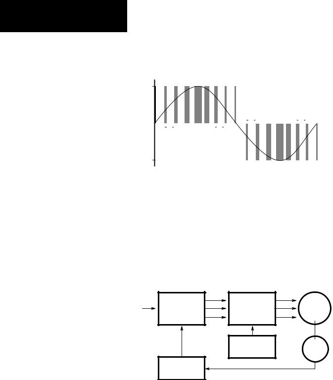
PWM Operation |
The 1391-DES incorporates a fixed timing wave (VT) of 2500 Hz. The |
|
drive generates a three-phase sine wave by varying the width of the fixed |
|
timing pulses (see Figure 4.1). This frequency corresponds to the velocity |
|
command. The 0 to 10V DC velocity command is scaled to provide an |
|
output frequency (dotted line) that varies from 0 to 200 Hz, depending on |
|
the maximum velocity of the motor. This variable frequency output drives |
|
a permanent magnet AC servomotor whose speed varies as a function of |
|
the frequency. |
4-1
Chapter 4
Description of Operation
Figure 4.1
PWM Waveform
300V DC
Bus
|
|
|
|
|
|
|
|
|
|
|
|
|
400 s |
|
|
400 s |
|||||||||
|
|
|
|
|
|
|
|
|
|
|
|
|
Typical |
|
|
Typical |
|||||||||
0 |
|
|
|
|
|
|
|
|
|
|
|
|
|
|
|
|
|
|
|
|
|
|
|
|
Time |
|
|
|
|
|
|
|
|
|
|
|
|
|
|
|
|
|
|
|
|
|
|
|
|
||
|
|
|
|
|
|
|
|
|
|
|
|
|
|
|
|
|
|
|
|
|
|
|
|
||
|
400 s |
|
|
400 s |
|
|
|
|
|
|
|
|
|
|
|
|
|
||||||||
|
Typical |
|
|
Typical |
|
|
|
|
|
|
|
|
|
||||||||||||
|
|
|
|
|
|
|
|
|
|
|
|
|
|
|
|
|
|
|
|
|
|
|
|
|
|
The three-phase relationship between the reference signal and the timing wave provide PWM pulses to the power transistor base drive. This base drive switches the power transistors across the 300V DC bus, providing current to the motor windings, thus causing the motor to turn. A resolver attached to the motor provides a signal corresponding to the actual rotor position of the motor. This signal is decoded to a signal representing rotor position and is fed to the commutation logic along with the torque command. In this way, the drive combines the desired position signal and current reference with the decoded resolver signal to produce a reference signal commanding the motor to speed up or slow down. See Figure 4.2.
Figure 4.2
Operation
Current |
Commutation |
PWM Generator |
Motor |
|
Logic & Current |
||||
Reference |
& Base Drive |
|||
Loop Integrator |
|
|||
|
|
|
||
|
|
Timing Signal |
Resolver |
|
|
|
Generator |
Position Decoder
4-2

Chapter 4
Description of Operation
Shunt Regulator Operation |
The 1391-DES shunt regulator provides power dissipation for regenerative |
|
conditions when the energy returned to the drive by the motor exceeds that |
|
which can be stored in the bus capacitors. The shunt regulator monitors the |
|
bus voltage and at a predetermined ªONº point activates the shunt |
|
regulator transistor, allowing current to flow through the shunt resistor and |
|
dissipating power in the form of heat. A fuse is placed in series with the |
|
resistor to protect it against short circuit conditions. When the shunt |
|
transistor is activated and power is being dissipated at the resistor, the bus |
|
voltage will quickly decrease, turning the transistor off when the voltage |
|
reaches the ªOFFº point. This cycle repeats, provided the bus voltage |
|
continues to increase to the ªONº point. If too much regenerative energy is |
|
present, the bus voltage will continue to increase even with the shunt |
|
regulator on. At a predetermined bus voltage level, the 1391-DES will |
|
determine that an overvoltage condition exists, and trip out on an |
|
Overvoltage Fault. |
|
The shunt regulator behavior is further modified by an adjustable duty |
|
cycle timer. The timer is used to model the shunt resistor temperature. |
|
SW1, a selector switch located on the top of the drive (see Figure 1.1) |
|
determines the temperature level and therefore the average power level at |
|
which the drive will trip out. When this level is reached, the drive will be |
|
forced to trip out on an Overvoltage Fault. This action would be equivalent |
|
to turning the shunt regulator off. Refer to Chapter 10 for further shunt |
|
regulator information. |
Logic Power Supply |
The 1391-DES control logic voltage is ±12V DC and +5V DC. The |
|
voltages are generated on the Power Driver Board, which receives its 36V |
|
AC input from a tertiary winding on the isolation transformer. |
Logic Control Boards |
The Logic Control Boards are the printed circuit boards that are readily |
|
accessible behind the front cover of the drive. They contain all circuits |
|
necessary to control the 1391-DES. These circuits include: the velocity and |
|
current loop, programming panel, A Quad B Board, fault detection and |
|
annunciation circuits, power-up/power-down logic, PWM generation and |
|
forward/reverse controlling circuits. |
Fault Monitoring and Detection |
A number of fault monitor and detection functions exist on the 1391-DES |
|
that guard the drive and help to minimize motor and system faults. The |
|
occurrence of a fault will cause the drive to trip out. In this condition, the |
|
Drive OK (DROK) contact will open and remain open until the fault is |
|
cleared. If the DROK contact is wired into the user's stop circuit, the |
|
line/DB contactor (M) will also de-energize. This will place the shunt |
|
resistor across the bus causing the motor to dynamic brake to a stop. |
|
These fault conditions are annunciated through the front panel display. The |
|
conditions displayed include: |
4-3

Chapter 4
Description of Operation
Overtemperature
The drive contains a thermal switch on the heat sink which indirectly senses transistor module temperature. If the temperature rating of the switch is exceeded, the DROK contact opens and the drive is disabled.
Power Fault
A fault related to the power bridge section of the drive will cause the drive to be disabled and open the DROK contact.
Control Voltage Fault
If the control voltage varies more than ±10% of the nominal 12V DC, this fault will occur. When a fault is detected, the DROK contact opens and the drive is disabled.
Resolver Loss Fault
If the resolver wiring is grounded or missing, this fault will occur. When a fault is detected, the DROK contact opens and the drive is disabled.
Overvoltage
The DC power bus voltage is continuously monitored. If it exceeds a preset level of 405V DC, the DROK contact opens and the drive is disabled
Undervoltage
If the DC power bus voltage drops below 50% of its nominal operating value an undervoltage fault occurs. Parameter 130 selects the reaction of the DROK contacts to an undervoltage detection. Two options are possible: 1) DROK opens, but closes when the bus voltage is restored; 2) DROK is not affected by an undervoltage.
Important: Regardless of interaction with the DROK contacts, the transistor bridge is disabled upon an undervoltage condition. This is done to protect the output transistors against voltage transients.
Current Foldback
The drive contains a fixed time versus current overload circuit which monitors the current through each leg of the output bridge. If the overload is sustained for a period, resulting in the drive rating being exceeded, the circuitry will reduce (foldback) the peak output current of the drive. A continuous overload will fold the available peak current down to its continuous rating. This condition will reduce the current limit or torque available to the motor.
Enable LED
The application of an enable signal by the machine position drive will cause the front panel ENABLE LED to illuminate.
Status LED
The status of the power supplies and fault conditions are monitored continuously. If a fault is present, the front panel FAULT/DRIVE READY LED will flash red and the DROK contact will be open. If the drive is operational, this LED will be green.
4-4

Chapter 4
Description of Operation
Microprocessor Control |
The 1391-DES is controlled by an 80C196KB microprocessor. Velocity |
|
|
control, sequencing, fault logic, programming and option control is |
|
|
performed by the processor. Current control is analog, as is the input |
|
|
velocity command. The input command is fed through a 14 bit digital to |
|
|
analog converter (13 bits/8192 resolution and a +/± sign bit). |
|
Isolated Current Sensing |
The Logic Control Boards receive current feedback from the Isolated |
|
|
Current Sense Board. This circuitry provides the data used for current loop |
|
|
closure. |
|
Integral Circuit Breaker |
The DC bus supply, input rectifier and power circuitry are protected against |
|
|
overcurrents by an integral three pole magnetic circuit breaker. This is not |
|
|
designed nor intended to meet NEC branch circuit requirements. |
|
Line/DB Contactor |
The three-phase incoming AC line is opened by the contactor whenever the |
|
|
voltage on the contactor coil is removed. This operation in conjunction |
|
|
with the shunt regulator reduces the bus voltage when the contactor is |
|
|
disabled. The Logic Control Board remains energized except when voltage |
|
|
is removed from the incoming isolation transformer. |
|
|
Important: The 1391-DES contains a definite purpose contactor that is not |
|
|
to be energized/de-energized more than twice an hour on a continuous |
|
|
basis. The life of the contactor may be reduced considerably if the cycle is |
|
|
exceeded. Contact your local Allen-Bradley Sales Representative for |
|
|
additional information. |
|
Power Driver Board |
The Power Driver Board contains the circuitry needed to switch the power |
|
|
transistor modules. |
|
A Quad B Board |
The A Quad B Board changes the resolver signal from a 1326AB or AD |
|
|
motor into an encoder signal for use by a position controller (such as an |
|
|
IMC S Class or 12x family controller). |
|
Starting and Stopping |
|
|
|
|
|
|
! |
ATTENTION: The Enable control circuitry in the 1391-DES |
|
includes solid-state components. If hazards due to accidental |
|
contact with moving machinery or unintentional flow of liquid, gas or solids exist, an additional hardwired stop circuit may be required. Refer to the codes and standards applicable to your particular system for specific requirements and additional information. A device that removes AC input power when a stop is initiated is an integral part of this drive. Refer to the following individual stop mode explanations.
4-5

Chapter 4
Description of Operation
ATTENTION: The user has the ultimate responsibility to
!determine which stopping method is best suited to the application and will meet applicable standards for operator safety.
Starting and Stopping must be accomplished by hardwired user supplied elements as shown in Appendix B. Stopping modes for the 1391-DES are outlined below. Refer to the paragraphs that follow for detailed information. The effects described below assume that the 36V AC control voltage has not been de-energized.
Cause |
Effect on Motor |
De-energize Line/DB Contactor (M) Coil |
Dynamic Brake |
Speed Command brought to Zero |
Regenerative Brake |
Open Enable Input |
Regenerative Brake |
DROK Opens (Fault) |
Coast to Stop |
Dynamic Braking
When the line/DB contactor (M) is de-energized by the control circuitry, an inherent dynamic braking effect will occur during the DC bus decay, provided the 36V AC logic voltage is not de-energized. The dynamic braking effect depends on the value of the shunt regulator resistor and total load inertia.
Important: Frequent cycling of the line/DB contactor to start/stop the motor will reduce the life of the contactor.
Regenerative Braking
Normal run commands to the drive are performed through the Enable input and any additional customer supplied control circuitry. Refer to Appendix B. With input power applied, a mechanical contact closure (or solid-state contact closure rated +15 to +30V DC, 30 mA) between TB2-9 & 10 will cause the drive to run, provided the line/DB contactor (M) has been energized by the control circuitry. When the Enable input is de-energized, the maximum available reverse torque is applied to the motor in a regenerative stopping mode, which will occur for approximately 450ms.
Coast
An internal drive fault opens the DROK contact. Coasting will only occur if the DROK contact is not wired to the line/DB contactor coil (M) or the Enable input circuits.
4-6
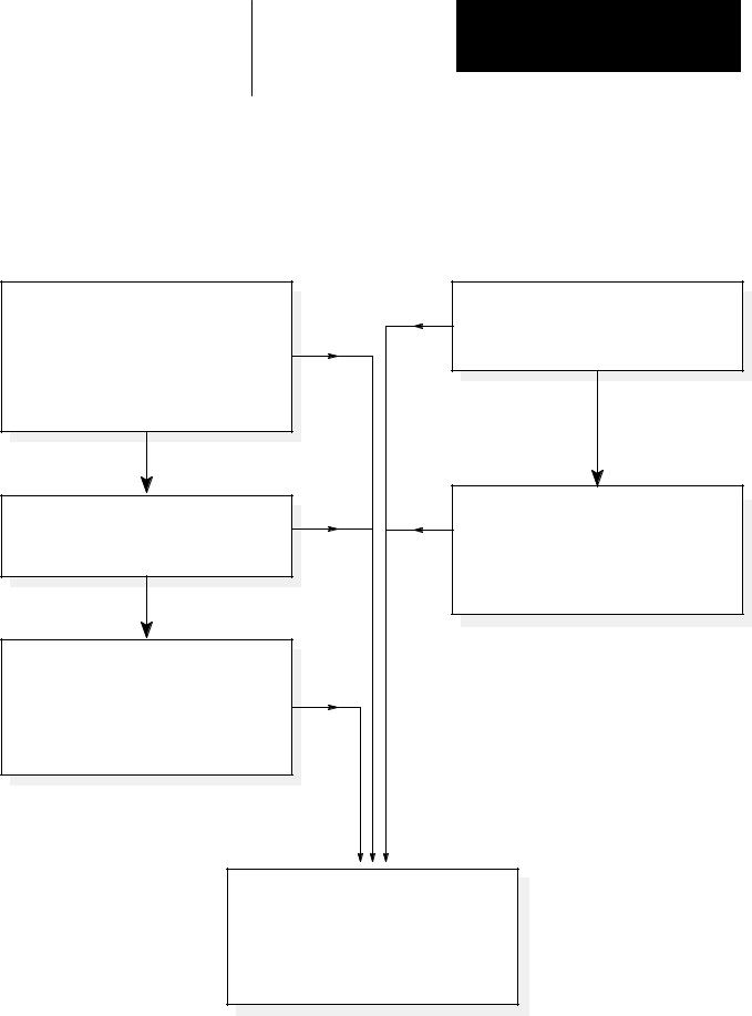
Chapter 4
Description of Operation
Power-Up/Down Sequence |
Figure 4.3 describes the various steps involved in the power-up/down |
|
sequence of the 1391-DES Drive. |
|
Figure 4.3 |
|
Drive Power-Up / Down Sequence |
POWER-UP SEQUENCE
Apply AC Input Power to Isolation Transformer
a)Logic power supplies and base drive circuits power-up.
b)Apply 115V AC to contactor.
c)Power bus charges.
d)If no faults are encountered, the DROK relay energizes. Drive is ready to receive customer enable signal.
Enable Signal Applied
Minimum of 100 ms after Contactor is Closed
a)Base drive enabled and will respond to velocity command inputs.
Enable Signal is Applied Prior to 36V AC Power
a)When 36V AC power is applied, fault circuits detect that the enable signal is already applied. Random fault conditions occur.
b)Re-application of enable after resetting the drive and with 36V AC power still present, will energize the drive.
Fault
Fault
Fault |
Fault |
Fault
POWER-DOWN SEQUENCE
Enable Signal Removed
a)Motor will regenerate to a stop.
b)Output power stage is disabled.
c)DROK relay maintains a no fault status.
AC Input Power Removed
a)Logic and DC link power supplies begin decaying to zero volts.
b)Undervoltage (fault) condition occurs.
c)DROK relay de-energizes based on setting of parameter 130.
Fault Condition Occurs
a)Drive output stage disabled.
b)DROK relay is de-energized and a fault is displayed.
c)If contactor (M) is wired to the DROK relay in a stop string, contactor will open and the shunt regulator will discharge the power bus supply.
4-7
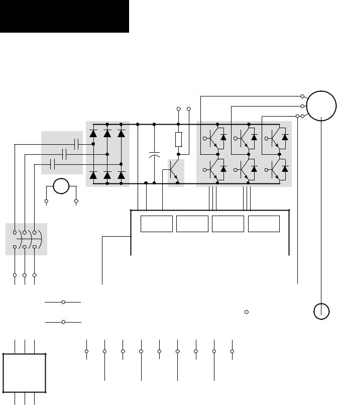
Chapter 4
Description of Operation
Figure 4.4
1391-DES Block Diagram
|
TB5±1 |
External Shunt |
TB5±2 |
TB5±3 |
Regulator |
1326A AC |
Resistor |
|
|
Servomotor |
Rectifier D1
Contactor |
|
|
|
|
|
M |
|
R1 |
|
|
|
M |
|
C1 |
|
|
|
M |
|
|
|
||
|
|
|
|
|
|
M |
|
|
Shunt |
|
Power Transistor |
|
|
|
|
||
TB4±11 |
TB4±12 |
|
Regulator |
|
Output Modules |
Transistor |
|
|
|||
|
|
|
|
||
Contactor Coil |
|
|
|
|
|
|
|
Shunt |
Transistor |
Logic |
Power Fault |
|
|
Regulator |
Base Drive |
Suppy |
Protection |
Circuit Breaker |
|
|
|
|
|
(MCB) |
|
Power Driver Board |
|
|
|
|
|
|
|
||
|
TB5±4 |
|
|
|
|
|
|
|
|
|
|
|
|
|
|
|
|
|
|
|
|
|
|
|
|
|
|
|
|
Isolated |
|
|
|
|
|||
|
TB5±5 |
|
|
|
|
|
|
|
|
|
|
|
|
|
||||
|
TB5±6 |
|
|
|
|
|
|
|
|
|
|
Current |
|
|
|
|
||
|
|
|
|
|
|
|
|
|
|
|
|
|
|
|
|
|||
|
|
|
|
|
|
|
|
|
|
|
|
|
Sense |
|
|
|
||
|
|
|
|
|
|
|
|
|
|
|
|
|
||||||
Isolation |
|
TB4±19 |
|
Protection |
|
Control |
|
|
|
LEDs |
|
Board |
|
|
|
|
||
|
TB4±21 |
|
|
|
|
|
|
|
|
|
||||||||
Transformer |
|
|
Circuitry |
|
|
Logic |
|
|
|
|
|
|
|
|
|
|
||
|
|
|
|
|
|
|
|
Status |
|
|
|
|
|
|
|
|||
(MPT) |
|
36V AC |
|
|
|
|
|
|
|
|
|
|
|
|
|
|
|
|
|
|
|
|
|
|
|
|
|
|
|
|
|
|
|
|
|||
|
|
|
|
|
|
|
|
|
Enable |
|
|
|
|
|
|
|
||
|
|
|
|
|
|
|
|
|
|
|
|
|
|
|
|
|
||
|
|
1±Phase |
|
|
|
|
|
|
|
|
|
TB1±1 |
|
|
|
|
|
|
|
|
|
|
|
|
|
|
|
|
|
|
|
|
|
|
|
|
|
|
|
|
|
|
|
|
|
|
|
|
|
through |
|
|
|
|
Brushless |
|
|
|
|
Digital Control Boards |
|
|
|
TB1±10 |
|
|
|
|
|||||||
|
|
|
|
|
|
|
|
|
|
|
Resolver |
|||||||
|
|
|
|
|
|
|
|
|
|
|
|
|
|
|
|
|
|
|
User Supplied
Branch Circuit
Protection &
Disconnect
AC Line Input
TB2±1 |
TB2±4 |
TB2±6 |
TB2±9 |
TB2±11 |
TB2±13 |
TB2±15 |
TB3±1 |
TB4±17 |
||
TB2±2 |
TB2±5 |
TB2±7 |
TB2±10 |
TB2±12 |
TB2±14 |
TB2±16 |
through |
TB4±18 |
||
TB2±3 |
|
|
|
|
|
|
|
|
TB3±10 |
|
Velocity |
Current |
|
|
|
|
|
||||
Reset |
Torque |
DROK |
||||||||
Command |
Output |
|
|
|
|
Command |
Contact |
|||
|
|
|
|
|
|
|
Input |
|
|
|
Velocity |
Enable |
|
Adjustable |
Encoder |
|
|||||
Output |
|
|
|
|
Current |
Output |
|
|||
|
|
|
|
|
|
Limit |
|
|
|
|
4-8

Chapter
Inputs, Outputs and Switch Settings
Chapter Objectives |
Chapter 5 contains descriptions of the various inputs and outputs available |
|
on the 1391-DES Digital Servo Drive. Additionally, information for |
|
properly setting the drive switches is provided for reference when you |
|
perform start-up. For information on shunt regulator adjustments, refer to |
|
Chapter 10. |
Inputs/Outputs |
The following paragraphs provide detailed descriptions of the various |
|
inputs and outputs available for the 1391-DES. See Figure 5.2 for terminal |
|
block locations. |
|
Terminal Block - TB1 |
|
Resolver Signals (TB1, Terminals 1-10) |
|
These terminals are used for connecting the commutation resolver from the |
|
motor to the drive. Refer to Appendix B for connection details. |
|
Important: Terminal 1 of TB1 must be connected to chassis ground at the |
|
Ground Stud (see Figure 5.2 for Ground Stud location). |
|
Terminal Block - TB2 |
|
Please note that there are no connections to TB2-18, 19 & 20. |
|
Velocity Command Input (TB2, Terminals 1, 2) |
|
The drive will accept up to a ±10V DC velocity command signal to achieve |
|
maximum motor speed. Voltages lower than ±10V DC can be used by |
|
reprogramming parameter 211 (Analog Velocity Gain). The plus (+) and |
|
minus (±) reference are at terminals 2 and 1, respectively. Shield must be |
|
terminated at one end only. The differential impedance of the velocity |
|
command input is 80k ohms (40k ohms for single ended inputs). |
|
Signal Common (TB2, Terminals 3, 5, 7, 8, 12, 17) |
|
Signal input reference point. |
|
Analog Out 1 (Velocity) (TB2, Terminal 4) |
|
A voltage corresponding to the motor velocity and direction of rotation will |
|
be present between this terminal and signal common (Terminal 5). +1.2V |
|
DC for each 1000 rpm is available. Minimum impedance that can be |
|
placed across this output is 10k ohm. |
5-1
Loading...