


 Loading...
User Manual
ControlLogix System
Catalog Numbers 1756-L61, 1756-L62, 1756-L63, 1756-L63XT, 1756-L64, 1756-L65, 1756-L71, 1756-L72, 1756-L73, 1756-L73XT, 1756-L74, 1756-L75

Important User Information
Solid-state equipment has operational characteristics differing from those of electromechanical equipment. Safety Guidelines for the Application, Installation and Maintenance of Solid State Controls (publication SGI-1.1 available from your local Rockwell Automation® sales office or online at http://www.rockwellautomation.com/literature/) describes some important differences between solid-state equipment and hard-wired electromechanical devices. Because of this difference, and also because of the wide variety of uses for solid-state equipment, all persons responsible for applying this equipment must satisfy themselves that each intended application of this equipment is acceptable.
In no event will Rockwell Automation, Inc. be responsible or liable for indirect or consequential damages resulting from the use or application of this equipment.
The examples and diagrams in this manual are included solely for illustrative purposes. Because of the many variables and requirements associated with any particular installation, Rockwell Automation, Inc. cannot assume responsibility or liability for actual use based on the examples and diagrams.
No patent liability is assumed by Rockwell Automation, Inc. with respect to use of information, circuits, equipment, or software described in this manual.
Reproduction of the contents of this manual, in whole or in part, without written permission of Rockwell Automation, Inc., is prohibited.
Throughout this manual, when necessary, we use notes to make you aware of safety considerations.
WARNING: Identifies information about practices or circumstances that can cause an explosion in a hazardous environment, which may lead to personal injury or death, property damage, or economic loss.
ATTENTION: Identifies information about practices or circumstances that can lead to personal injury or death, property damage, or economic loss. Attentions help you identify a hazard, avoid a hazard, and recognize the consequence.
SHOCK HAZARD: Labels may be on or inside the equipment, for example, a drive or motor, to alert people that dangerous voltage may be present.
BURN HAZARD: Labels may be on or inside the equipment, for example, a drive or motor, to alert people that surfaces may reach dangerous temperatures.
IMPORTANT Identifies information that is critical for successful application and understanding of the product.
Allen-Bradley, ArmorBlock, ArmorBlock MaXum, ArmorPOINT, Compact I/O, CompactLogix, ControlFLASH, ControlLogix, ControlLogix-XT, Data Highway Plus, DH+, DriveLogix, FactoryTalk, FLEX, FLEX Ex, FlexLogix, GuardLogix, Guard PLC, Integrated Architecture, Kinetix, Logix5000, Logix5550, Logix Designer, MessageView, MicroLogix, PanelView, PhaseManager, PLC-5, POINT I/O, PowerFlex, RediSTATION, Rockwell Automation, Rockwell Software, RSBizWare, RSFieldbus, RSLinx, RSLogix, RSNetWorx, RSView, RSWho, Series 9000, SLC, Studio 5000, Studio 5000 Automation & Engineering Design Environment, Studio 5000 Logix Designer, and Stratix 8000 are trademarks of Rockwell Automation.
Trademarks not belonging to Rockwell Automation are property of their respective companies.

Summary of Changes
New and Updated
Information
This manual contains new and updated information. Changes throughout this revision are marked by change bars, as shown to the right of this paragraph.
This table contains the changes made to this revision.
Topic |
Page |
|
|
Added DLR segment to EtherNet/IP Network Example. |
86 |
|
|
Added DH+ Modules and Capabilities table. |
95 |
|
|
Added Access the Module Object section to Develop Applications chapter. |
160 |
|
|
Updated screenshots and descriptions for the Studio 5000 environment version 24. |
Throughout publication |
|
|
Rockwell Automation Publication 1756-UM001O-EN-P - October 2014 |
3 |

Summary of Changes
Notes:
4 |
Rockwell Automation Publication 1756-UM001O-EN-P - October 2014 |

|
Table of Contents |
|
Preface |
Studio 5000 Environment . . . . . . . . . . . . . . . . . . . . . . . . . . . . . . . . . . . . . . . . |
11 |
|
ControlLogix Controllers Overview . . . . . . . . . . . . . . . . . . . . . . . . . . . . . . . |
11 |
|
Standard ControlLogix Controllers . . . . . . . . . . . . . . . . . . . . . . . . . . . . |
12 |
|
Redundant ControlLogix Controllers. . . . . . . . . . . . . . . . . . . . . . . . . . |
13 |
|
Extreme Environment ControlLogix Controllers . . . . . . . . . . . . . . . |
13 |
|
Before You Begin . . . . . . . . . . . . . . . . . . . . . . . . . . . . . . . . . . . . . . . . . . . . . . . . |
14 |
|
Required Software. . . . . . . . . . . . . . . . . . . . . . . . . . . . . . . . . . . . . . . . . . . . |
14 |
|
Additional Resources . . . . . . . . . . . . . . . . . . . . . . . . . . . . . . . . . . . . . . . . . . . . . |
15 |
|
Chapter 1 |
|
Install the 1756-L7x Controller |
Before You Begin . . . . . . . . . . . . . . . . . . . . . . . . . . . . . . . . . . . . . . . . . . . . . . . . |
21 |
|
1756-L7x Controller Parts . . . . . . . . . . . . . . . . . . . . . . . . . . . . . . . . . . . . . . . . |
21 |
|
Parts Included with the 1756-L7x Controller . . . . . . . . . . . . . . . . . . . |
21 |
|
Parts Available for Use with the 1756-L7x Controller . . . . . . . . . . . |
22 |
|
1756-L7x Controller Installation . . . . . . . . . . . . . . . . . . . . . . . . . . . . . . . . . . |
22 |
|
Insert the Controller into the Chassis . . . . . . . . . . . . . . . . . . . . . . . . . . . . . . |
23 |
|
Insert the Key. . . . . . . . . . . . . . . . . . . . . . . . . . . . . . . . . . . . . . . . . . . . . . . . . . . . |
24 |
|
Install the SD Card. . . . . . . . . . . . . . . . . . . . . . . . . . . . . . . . . . . . . . . . . . . . . . . |
25 |
|
Remove the SD Card . . . . . . . . . . . . . . . . . . . . . . . . . . . . . . . . . . . . . . . . . . . . . |
26 |
|
Install the ESM . . . . . . . . . . . . . . . . . . . . . . . . . . . . . . . . . . . . . . . . . . . . . . . . . . |
28 |
|
Uninstall the ESM . . . . . . . . . . . . . . . . . . . . . . . . . . . . . . . . . . . . . . . . . . . . . . . |
29 |
|
Chapter 2 |
|
Install the 1756-L6x Controller |
Before You Begin . . . . . . . . . . . . . . . . . . . . . . . . . . . . . . . . . . . . . . . . . . . . . . . . |
35 |
|
1756-L6x Controller Parts . . . . . . . . . . . . . . . . . . . . . . . . . . . . . . . . . . . . . . . . |
35 |
|
Parts Not Included with the 1756-L6x Controller. . . . . . . . . . . . . . . |
35 |
|
1756-L6x Controller Installation . . . . . . . . . . . . . . . . . . . . . . . . . . . . . . . . . . |
36 |
|
CompactFlash Card Installation and Removal. . . . . . . . . . . . . . . . . . . . . . |
36 |
|
Battery Connection and Replacement . . . . . . . . . . . . . . . . . . . . . . . . . . . . . |
39 |
|
Insert the Controller into the Chassis . . . . . . . . . . . . . . . . . . . . . . . . . . . . . . |
42 |
|
Remove the Controller from the Chassis . . . . . . . . . . . . . . . . . . . . . . . . . . . |
44 |
|
Chapter 3 |
|
Start Using the Controller |
Make Connections . . . . . . . . . . . . . . . . . . . . . . . . . . . . . . . . . . . . . . . . . . . . . . . |
45 |
|
1756-L7x Connection Options . . . . . . . . . . . . . . . . . . . . . . . . . . . . . . . . |
45 |
|
1756-L6x Connection Options . . . . . . . . . . . . . . . . . . . . . . . . . . . . . . . . |
46 |
|
Connect to the 1756-L7x Controller . . . . . . . . . . . . . . . . . . . . . . . . . . . . . . |
46 |
|
Configure the USB Driver . . . . . . . . . . . . . . . . . . . . . . . . . . . . . . . . . . . . |
47 |
|
Connect to the 1756-L6x Controller . . . . . . . . . . . . . . . . . . . . . . . . . . . . . . |
49 |
|
Configure the Serial Driver. . . . . . . . . . . . . . . . . . . . . . . . . . . . . . . . . . . . |
50 |
|
Upgrade Controller Firmware. . . . . . . . . . . . . . . . . . . . . . . . . . . . . . . . . . . . . |
52 |
|
Determine Required Controller Firmware. . . . . . . . . . . . . . . . . . . . . . |
52 |
|
Obtain Controller Firmware . . . . . . . . . . . . . . . . . . . . . . . . . . . . . . . . . . |
53 |
|
Use ControlFLASH Software to Upgrade Firmware . . . . . . . . . . . . |
53 |
Rockwell Automation Publication 1756-UM001O-EN-P - October 2014 |
5 |

Table of Contents |
|
|
|
Use AutoFlash to Upgrade Firmware . . . . . . . . . . . . . . . . . . . . . . . . . . . |
56 |
|
Set the Communication Path. . . . . . . . . . . . . . . . . . . . . . . . . . . . . . . . . . . . . . |
58 |
|
Go Online with the Controller . . . . . . . . . . . . . . . . . . . . . . . . . . . . . . . . . . . . |
58 |
|
Download to the Controller. . . . . . . . . . . . . . . . . . . . . . . . . . . . . . . . . . . . . . . |
59 |
|
Use the Who Active Dialog Box to Download . . . . . . . . . . . . . . . . . . |
59 |
|
Use the Controller Status Menu to Download . . . . . . . . . . . . . . . . . . |
60 |
|
Upload from the Controller . . . . . . . . . . . . . . . . . . . . . . . . . . . . . . . . . . . . . . . |
60 |
|
Use the Who Active Dialog Box to Upload . . . . . . . . . . . . . . . . . . . . . |
60 |
|
Use the Controller Status Menu to Upload . . . . . . . . . . . . . . . . . . . . . |
61 |
|
Choose the Controller Operation Mode . . . . . . . . . . . . . . . . . . . . . . . . . . . |
62 |
|
Use the Mode Switch to Change the Operation Mode . . . . . . . . . . . |
62 |
|
Use Logix Designer to Change the Operation Mode . . . . . . . . . . . . . |
64 |
|
Load or Store to the Memory Card . . . . . . . . . . . . . . . . . . . . . . . . . . . . . . . . |
65 |
|
Store to the Memory Card. . . . . . . . . . . . . . . . . . . . . . . . . . . . . . . . . . . . . |
65 |
|
Load from the Memory Card . . . . . . . . . . . . . . . . . . . . . . . . . . . . . . . . . . |
68 |
|
Other Memory Card Tasks . . . . . . . . . . . . . . . . . . . . . . . . . . . . . . . . . . . . |
70 |
|
Use ControlLogix Energy Storage Modules (ESMs) . . . . . . . . . . . . . . . . . |
70 |
|
Save the Program to On-board NVS Memory . . . . . . . . . . . . . . . . . . . |
71 |
|
Clear the Program from On-board NVS Memory . . . . . . . . . . . . . . . |
71 |
|
Estimate the ESM Support of the WallClockTime . . . . . . . . . . . . . . . . . . |
72 |
|
Maintain the Battery (Only 1756-L6x Controllers) . . . . . . . . . . . . . . . . . |
72 |
|
Check the Battery Status . . . . . . . . . . . . . . . . . . . . . . . . . . . . . . . . . . . . . . |
72 |
|
1756-BA1 or 1756-BATA Battery Life . . . . . . . . . . . . . . . . . . . . . . . . . |
73 |
|
1756-BATM Battery Module and Battery Life . . . . . . . . . . . . . . . . . . |
74 |
|
Estimate 1756-BA2 Battery Life . . . . . . . . . . . . . . . . . . . . . . . . . . . . . . . |
75 |
|
Estimate 1756-BA2 Battery Life After Warnings . . . . . . . . . . . . . . . . |
76 |
|
Battery Storage and Disposal. . . . . . . . . . . . . . . . . . . . . . . . . . . . . . . . . . . |
77 |
|
Chapter 4 |
|
ControlLogix System and Controllers |
ControlLogix System . . . . . . . . . . . . . . . . . . . . . . . . . . . . . . . . . . . . . . . . . . . . . |
79 |
|
Configuration Options. . . . . . . . . . . . . . . . . . . . . . . . . . . . . . . . . . . . . . . . |
79 |
|
Design a ControlLogix System. . . . . . . . . . . . . . . . . . . . . . . . . . . . . . . . . . . . . |
81 |
|
ControlLogix Controller Features . . . . . . . . . . . . . . . . . . . . . . . . . . . . . . . . . |
82 |
|
System, Communication, and Programming Features. . . . . . . . . . . . |
82 |
|
Memory Options . . . . . . . . . . . . . . . . . . . . . . . . . . . . . . . . . . . . . . . . . . . . . |
83 |
|
Electronic Keying. . . . . . . . . . . . . . . . . . . . . . . . . . . . . . . . . . . . . . . . . . . . . |
84 |
|
Chapter 5 |
|
Communication Networks |
Networks Available. . . . . . . . . . . . . . . . . . . . . . . . . . . . . . . . . . . . . . . . . . . . . . . |
85 |
|
EtherNet/IP Network Communication . . . . . . . . . . . . . . . . . . . . . . . . . . . . |
86 |
|
ControlLogix EtherNet/IP Module Features. . . . . . . . . . . . . . . . . . . . |
86 |
|
ControlLogix EtherNet/IP Communication Modules . . . . . . . . . . . |
87 |
|
Software for EtherNet/IP Networks. . . . . . . . . . . . . . . . . . . . . . . . . . . . |
88 |
|
Connections Over an EtherNet/IP Network. . . . . . . . . . . . . . . . . . . . |
88 |
|
Double Data Rate (DDR) Backplane Communication. . . . . . . . . . . |
88 |
|
ControlNet Network Communication. . . . . . . . . . . . . . . . . . . . . . . . . . . . . |
89 |
6 |
Rockwell Automation Publication 1756-UM001O-EN-P - October 2014 |

Table of Contents
Serial Communication on 1756-L6x Controllers
ControlLogix ControlNet Module Features . . . . . . . . . . . . . . . . . . . . 90 ControlLogix ControlNet Modules. . . . . . . . . . . . . . . . . . . . . . . . . . . . 91
Software for ControlNet Networks . . . . . . . . . . . . . . . . . . . . . . . . . . . . 91
Connections Over a ControlNet Network . . . . . . . . . . . . . . . . . . . . . 92 DeviceNet Network Communication. . . . . . . . . . . . . . . . . . . . . . . . . . . . . . 92
ControlLogix DeviceNet Module Features . . . . . . . . . . . . . . . . . . . . . 93
ControlLogix DeviceNet Bridge Module and Linking Devices . . . 94
Software for DeviceNet Networks . . . . . . . . . . . . . . . . . . . . . . . . . . . . . 94 Connections Over DeviceNet Networks . . . . . . . . . . . . . . . . . . . . . . . 94
ControlLogix DeviceNet Module Memory . . . . . . . . . . . . . . . . . . . . . 94
Data Highway Plus (DH+) Network Communication . . . . . . . . . . . . . . 95 Communicate Over a DH+ Network . . . . . . . . . . . . . . . . . . . . . . . . . . 96
Universal Remote I/O (RIO) Communication . . . . . . . . . . . . . . . . . . . . . 97
Communicate Over a Universal Remote I/O Network . . . . . . . . . . 97 Foundation Fieldbus Communication . . . . . . . . . . . . . . . . . . . . . . . . . . . . . 98
HART Communication. . . . . . . . . . . . . . . . . . . . . . . . . . . . . . . . . . . . . . . . . . 99
Chapter 6
1756-L6x Controller Serial Port. . . . . . . . . . . . . . . . . . . . . . . . . . . . . . . . . . 102 ControlLogix Chassis Serial Communication Options . . . . . . . . . 102
Communication with Serial Devices . . . . . . . . . . . . . . . . . . . . . . . . . . . . . . 103
DF1 Master Protocol . . . . . . . . . . . . . . . . . . . . . . . . . . . . . . . . . . . . . . . . . . . . 104 DF1 Point to Point Protocol . . . . . . . . . . . . . . . . . . . . . . . . . . . . . . . . . . . . . 105
DF1 Radio Modem Protocol . . . . . . . . . . . . . . . . . . . . . . . . . . . . . . . . . . . . . 106
DF1 Radio Modem Advantages . . . . . . . . . . . . . . . . . . . . . . . . . . . . . . 106 DF1 Radio Modem Limitations . . . . . . . . . . . . . . . . . . . . . . . . . . . . . . 107
DF1 Radio Modem Protocol Parameters . . . . . . . . . . . . . . . . . . . . . . 108
DF1 Slave Protocol. . . . . . . . . . . . . . . . . . . . . . . . . . . . . . . . . . . . . . . . . . . . . . 109 DH-485 Protocol . . . . . . . . . . . . . . . . . . . . . . . . . . . . . . . . . . . . . . . . . . . . . . . 110
ASCII Protocol . . . . . . . . . . . . . . . . . . . . . . . . . . . . . . . . . . . . . . . . . . . . . . . . . 112
Configure the 1756-L6x Controller for Serial Communication . . . . . 113 Broadcast Messages Over a Serial Port. . . . . . . . . . . . . . . . . . . . . . . . . . . . . 115
Configure Controller Serial Port Properties . . . . . . . . . . . . . . . . . . . 115 Program the Message Instruction . . . . . . . . . . . . . . . . . . . . . . . . . . . . . 117
Modbus Support . . . . . . . . . . . . . . . . . . . . . . . . . . . . . . . . . . . . . . . . . . . . . . . . 118
Chapter 7
Manage Controller Communication Connection Overview . . . . . . . . . . . . . . . . . . . . . . . . . . . . . . . . . . . . . . . . . . . 119
Produce and Consume (Interlock) Data . . . . . . . . . . . . . . . . . . . . . . . . . . 119
Connection Requirements of a Produced or Consumed Tag . . . . 120
Send and Receive Messages. . . . . . . . . . . . . . . . . . . . . . . . . . . . . . . . . . . . . . . 121
Determine Whether to Cache Message Connections . . . . . . . . . . . 122
Calculate Connection Use . . . . . . . . . . . . . . . . . . . . . . . . . . . . . . . . . . . . . . . 122
Local Connections . . . . . . . . . . . . . . . . . . . . . . . . . . . . . . . . . . . . . . . . . . 123
Remote Connections . . . . . . . . . . . . . . . . . . . . . . . . . . . . . . . . . . . . . . . . 123
Connections Example . . . . . . . . . . . . . . . . . . . . . . . . . . . . . . . . . . . . . . . 124
Rockwell Automation Publication 1756-UM001O-EN-P - October 2014 |
7 |

Table of Contents |
|
|
|
Chapter 8 |
|
I/O Modules |
Selecting ControlLogix |
|
|
I/O Modules. . . . . . . . . . . . . . . . . . . . . . . . . . . . . . . . . . . . . . . . . . . . . . . . . . . . |
127 |
|
Local I/O Modules . . . . . . . . . . . . . . . . . . . . . . . . . . . . . . . . . . . . . . . . . . . . . . |
127 |
|
Add Local I/O to the I/O Configuration . . . . . . . . . . . . . . . . . . . . . . |
128 |
|
Remote I/O Modules . . . . . . . . . . . . . . . . . . . . . . . . . . . . . . . . . . . . . . . . . . . . |
129 |
|
Add Remote I/O to the I/O Configuration . . . . . . . . . . . . . . . . . . . . |
130 |
|
Distributed I/O . . . . . . . . . . . . . . . . . . . . . . . . . . . . . . . . . . . . . . . . . . . . . . . . . |
132 |
|
Add Distributed I/O to the I/O Configuration . . . . . . . . . . . . . . . . |
133 |
|
Reconfigure an I/O Module . . . . . . . . . . . . . . . . . . . . . . . . . . . . . . . . . . . . . |
135 |
|
Reconfigure an I/O Module Via the Module Properties . . . . . . . . . |
135 |
|
Reconfigure an I/O Module Via a Message Instruction. . . . . . . . . . |
137 |
|
Add to the I/O Configuration While Online . . . . . . . . . . . . . . . . . . . . . . |
137 |
|
Modules and Devices that Can be Added While Online. . . . . . . . . |
137 |
|
Online Additions - ControlNet Considerations . . . . . . . . . . . . . . . . |
138 |
|
Online Additions—EtherNet/IP Considerations . . . . . . . . . . . . . . |
141 |
|
Determine When Data is Updated. . . . . . . . . . . . . . . . . . . . . . . . . . . . . . . . |
141 |
|
Chapter 9 |
|
Develop Motion Applications |
Motion Control Options . . . . . . . . . . . . . . . . . . . . . . . . . . . . . . . . . . . . . . . . |
143 |
|
Motion Overview . . . . . . . . . . . . . . . . . . . . . . . . . . . . . . . . . . . . . . . . . . . . . . . |
144 |
|
Obtain Axis Information. . . . . . . . . . . . . . . . . . . . . . . . . . . . . . . . . . . . . . . . . |
144 |
|
Program Motion Control . . . . . . . . . . . . . . . . . . . . . . . . . . . . . . . . . . . . . . . . |
145 |
|
Example . . . . . . . . . . . . . . . . . . . . . . . . . . . . . . . . . . . . . . . . . . . . . . . . . . . . |
145 |
|
Chapter 10 |
|
Develop Applications |
Elements of a Control Application. . . . . . . . . . . . . . . . . . . . . . . . . . . . . . . . |
147 |
|
Tasks . . . . . . . . . . . . . . . . . . . . . . . . . . . . . . . . . . . . . . . . . . . . . . . . . . . . . . . . . . . |
148 |
|
Task Priority . . . . . . . . . . . . . . . . . . . . . . . . . . . . . . . . . . . . . . . . . . . . . . . . |
151 |
|
Programs . . . . . . . . . . . . . . . . . . . . . . . . . . . . . . . . . . . . . . . . . . . . . . . . . . . . . . . |
151 |
|
Scheduled and Unscheduled Programs . . . . . . . . . . . . . . . . . . . . . . . . |
153 |
|
Routines. . . . . . . . . . . . . . . . . . . . . . . . . . . . . . . . . . . . . . . . . . . . . . . . . . . . . . . . |
154 |
|
Parameters and Local Tags . . . . . . . . . . . . . . . . . . . . . . . . . . . . . . . . . . . . . . . |
155 |
|
Extended Properties . . . . . . . . . . . . . . . . . . . . . . . . . . . . . . . . . . . . . . . . . |
156 |
|
Access Extended Properties in Logic. . . . . . . . . . . . . . . . . . . . . . . . . . . |
156 |
|
Programming Languages . . . . . . . . . . . . . . . . . . . . . . . . . . . . . . . . . . . . . . . . . |
158 |
|
Add-On Instructions . . . . . . . . . . . . . . . . . . . . . . . . . . . . . . . . . . . . . . . . . . . . |
159 |
|
Access the Module Object. . . . . . . . . . . . . . . . . . . . . . . . . . . . . . . . . . . . . . . . |
160 |
|
Create the Add-On Instruction . . . . . . . . . . . . . . . . . . . . . . . . . . . . . . . |
160 |
|
Monitoring Controller Status . . . . . . . . . . . . . . . . . . . . . . . . . . . . . . . . . . . . |
161 |
|
Monitoring I/O Connections . . . . . . . . . . . . . . . . . . . . . . . . . . . . . . . . . . . . |
162 |
|
Determine if I/O Communication has Timed Out . . . . . . . . . . . . . |
163 |
|
Determine if I/O Communication to a Specific I/O Module has |
|
|
Timed Out. . . . . . . . . . . . . . . . . . . . . . . . . . . . . . . . . . . . . . . . . . . . . . . . . . |
163 |
|
Interrupt the Execution of Logic and Execute the Fault Handler. 164 |
|
|
System Overhead Time Slice . . . . . . . . . . . . . . . . . . . . . . . . . . . . . . . . . . . . . |
165 |
8 |
Rockwell Automation Publication 1756-UM001O-EN-P - October 2014 |

|
|
Table of Contents |
|
Configure the System Overhead Time Slice. . . . . . . . . . . . . |
. . . . . . . 166 |
|
Sample Controller Projects. . . . . . . . . . . . . . . . . . . . . . . . . . . . |
. . . . . . . 167 |
|
Chapter 11 |
|
Using the PhaseManager Tool |
PhaseManager Overview. . . . . . . . . . . . . . . . . . . . . . . . . . . . . . . . . . . |
. . . . . . 169 |
|
Minimum System Requirements . . . . . . . . . . . . . . . . . . . . . . . . . . . |
. . . . . . 171 |
|
State Model Overview . . . . . . . . . . . . . . . . . . . . . . . . . . . . . . . . . . . . . |
. . . . . . 171 |
|
How Equipment Changes States. . . . . . . . . . . . . . . . . . . . . . . . |
. . . . . . 172 |
|
Manually Change States . . . . . . . . . . . . . . . . . . . . . . . . . . . . . . . |
. . . . . . 173 |
|
PhaseManager Tool versus Other State Models . . . . . . . . . . . . . . |
. . . . . . 174 |
|
Equipment Phase Instructions . . . . . . . . . . . . . . . . . . . . . . . . . . . . . |
. . . . . . 174 |
|
Chapter 12 |
|
Redundant Systems |
ControlLogix Redundancy Overview . . . . . . . . . . . . . . . . . . . . . . . |
. . . . . . 175 |
|
System Requirements. . . . . . . . . . . . . . . . . . . . . . . . . . . . . . . . . . . . . . |
. . . . . . 177 |
|
System Considerations . . . . . . . . . . . . . . . . . . . . . . . . . . . . . . . . . . . . |
. . . . . . 178 |
|
Enhanced Versus Standard Redundancy. . . . . . . . . . . . . . . . . |
. . . . . . 179 |
|
Build a Redundant System . . . . . . . . . . . . . . . . . . . . . . . . . . . . . . . . . |
. . . . . . 179 |
|
ControlNet Considerations in Redundant Systems . . . . . . . . . . |
. . . . . . 180 |
|
EtherNet/IP Considerations in Redundant Systems . . . . . . . . . |
. . . . . . 180 |
|
IP Address Swapping . . . . . . . . . . . . . . . . . . . . . . . . . . . . . . . . . . |
. . . . . . 180 |
|
Redundancy and Scan Time. . . . . . . . . . . . . . . . . . . . . . . . . . . . . . . . |
. . . . . . 181 |
|
Appendix A |
|
Troubleshoot the Module |
Use Logix Designer Application for Troubleshooting . . . . . . . . |
. . . . . . 183 |
|
Fault Type Determination . . . . . . . . . . . . . . . . . . . . . . . . . . . . . |
. . . . . . 185 |
|
1756-L7x Controller Status Display and Indicators . . . . . . . . . . |
. . . . . . 186 |
|
1756-L7x Controller Status Display . . . . . . . . . . . . . . . . . . . . . . . . |
. . . . . . 186 |
|
General Status Messages . . . . . . . . . . . . . . . . . . . . . . . . . . . . . . . |
. . . . . . 186 |
|
Fault Messages . . . . . . . . . . . . . . . . . . . . . . . . . . . . . . . . . . . . . . . . |
. . . . . . 187 |
|
Major Fault Messages . . . . . . . . . . . . . . . . . . . . . . . . . . . . . . . . . . |
. . . . . . 189 |
|
I/O Fault Codes. . . . . . . . . . . . . . . . . . . . . . . . . . . . . . . . . . . . . . . |
. . . . . . 191 |
|
1756-L7x Controller Status Indicators . . . . . . . . . . . . . . . . . . . . . . |
. . . . . . 195 |
|
RUN Indicator. . . . . . . . . . . . . . . . . . . . . . . . . . . . . . . . . . . . . . . . |
. . . . . . 195 |
|
FORCE Indicator . . . . . . . . . . . . . . . . . . . . . . . . . . . . . . . . . . . . . |
. . . . . . 195 |
|
SD Indicator . . . . . . . . . . . . . . . . . . . . . . . . . . . . . . . . . . . . . . . . . . |
. . . . . . 195 |
|
OK Indicator . . . . . . . . . . . . . . . . . . . . . . . . . . . . . . . . . . . . . . . . . |
. . . . . . 196 |
|
1756-L6x Status Indicators . . . . . . . . . . . . . . . . . . . . . . . . . . . . . . . . |
. . . . . . 196 |
|
RUN Indicator. . . . . . . . . . . . . . . . . . . . . . . . . . . . . . . . . . . . . . . . |
. . . . . . 196 |
|
I/O Indicator . . . . . . . . . . . . . . . . . . . . . . . . . . . . . . . . . . . . . . . . . |
. . . . . . 197 |
|
FORCE Indicator . . . . . . . . . . . . . . . . . . . . . . . . . . . . . . . . . . . . . |
. . . . . . 197 |
|
RS232 Indicator. . . . . . . . . . . . . . . . . . . . . . . . . . . . . . . . . . . . . . . |
. . . . . . 197 |
|
BAT Indicator . . . . . . . . . . . . . . . . . . . . . . . . . . . . . . . . . . . . . . . . |
. . . . . . 198 |
|
OK Indicator . . . . . . . . . . . . . . . . . . . . . . . . . . . . . . . . . . . . . . . . . |
. . . . . . 198 |
Rockwell Automation Publication 1756-UM001O-EN-P - October 2014 |
9 |

Table of Contents |
|
|
|
Appendix B |
|
History of Changes |
1756-UM001N-EN-P, November, 2012 . . . . . . . . . . . . . . . . . . . . . . . . . . |
200 |
|
1756-UM001M-EN-P, February 2012 . . . . . . . . . . . . . . . . . . . . . . . . . . . . |
200 |
|
1756-UM001L-EN-P, November 2011 . . . . . . . . . . . . . . . . . . . . . . . . . . . |
200 |
|
1756-UM001K-EN-P, May 2011. . . . . . . . . . . . . . . . . . . . . . . . . . . . . . . . . |
200 |
|
1756-UM001J-EN-P, July 2010 . . . . . . . . . . . . . . . . . . . . . . . . . . . . . . . . . . |
201 |
|
1756-UM001I-EN-P, January 2007. . . . . . . . . . . . . . . . . . . . . . . . . . . . . . . |
201 |
|
1756-UM001H-EN-P, July 2008 . . . . . . . . . . . . . . . . . . . . . . . . . . . . . . . . . |
201 |
|
1756-UM001G-EN-P, January 2007. . . . . . . . . . . . . . . . . . . . . . . . . . . . . . |
201 |
|
1756-UM001F-EN-P, May 2005 . . . . . . . . . . . . . . . . . . . . . . . . . . . . . . . . . |
201 |
|
1756-UM001E-EN-P, August 2002 . . . . . . . . . . . . . . . . . . . . . . . . . . . . . . |
202 |
|
1756-UM001D-EN-P . . . . . . . . . . . . . . . . . . . . . . . . . . . . . . . . . . . . . . . . . . . |
202 |
|
1756-UM001C-EN-P, June 2001 . . . . . . . . . . . . . . . . . . . . . . . . . . . . . . . . |
202 |
|
1756-UM001B-EN-P, November 2000 . . . . . . . . . . . . . . . . . . . . . . . . . . . |
202 |
Index |
|
|
10 |
Rockwell Automation Publication 1756-UM001O-EN-P - October 2014 |
Preface
Studio 5000 Environment
ControlLogix Controllers
Overview
The Studio 5000 Automation Engineering & Design Environment™ combines engineering and design elements into a common environment. The first element in the Studio 5000® environment is the Studio 5000 Logix Designer™ application. The Logix Designer application is the rebranding of RSLogix™ 5000 software and continues to be the product to program Logix5000™ controllers for discrete, process, batch, motion, safety, and drive-based solutions.
The Studio 5000 environment is the foundation for the future of Rockwell Automation® engineering design tools and capabilities. This
environment is the one place for design engineers to develop the elements of their control system.
There are three types of ControlLogix® controllers available. These types include the following:
•Standard ControlLogix controllers
•Extreme environment ControlLogix controllers
•GuardLogix® controllers
This manual explains how to use standard and extreme environment ControlLogix controllers.
Rockwell Automation Publication 1756-UM001O-EN-P - October 2014 |
11 |

Preface
For detailed information about GuardLogix safety controllers, see the following publications.
|
|
Resource |
Description |
|
|
|
|
|
|
GuardLogix 5570 Controllers User Manual, publication |
Provides information on how to install, configure, and |
|
|
||
|
|
1756-UM022 |
operate GuardLogix 5570 controllers in Studio 5000, |
|
|
|
version 21 or later projects. |
|
|
|
|
|
|
GuardLogix 5570 Controller System Safety Reference |
Provides information on how to meet safety application |
|
|
||
|
|
Manual, publication 1756-RM099 |
requirements for GuardLogix 5570 controllers in Studio |
|
|
|
5000, version 21 or later projects. |
|
|
|
|
|
|
GuardLogix Controllers User Manual, publication |
Provides information on how to install, configure, and |
|
|
||
|
|
1756-UM020 |
operate GuardLogix 5560 and GuardLogix 5570 controllers |
|
|
|
in RSLogix 5000, version 20 or earlier projects. |
|
|
|
|
|
|
GuardLogix Controller Systems Safety Reference Manual, |
Provides information on how to meet safety application |
|
|
||
|
|
publication 1756-RM093 |
requirements for GuardLogix 5560 and GuardLogix 5570 |
|
|
|
controllers in RSLogix 5000, version 20 or earlier projects. |
|
|
|
|
|
|
GuardLogix Safety Application Instruction Set Safety |
Provides programmers with details about the GuardLogix |
|
|
||
|
|
Reference Manual, publication 1756-RM095 |
safety application instruction set. |
|
|
|
|
Standard ControlLogix Controllers
Two lines of standard ControlLogix controllers are now available. These controllers are identified as 1756-L6x controllers and 1756-L7x controllers according to abbreviations of their full catalog numbers.
Table 1 - ControlLogix Catalog Numbers
Abbreviated Cat. No. |
Cat. No. |
|
|
1756-L6x |
1756-L61, 1756-L62,1756-L63, 1756-L64,1756-L65 |
|
|
1756-L7x |
1756-L71, 1756-L72, 1756-L73,1756-L74, 1756-L75 |
|
|
The standard ControlLogix controllers share many similar features, but also have some differences. Table 2 provides a brief overview the differences between the controllers. For further details about these features and differences, see the appropriate chapters of this manual.
Table 2 - Differences between 1756-L7x and 1756-L6x Controllers
Feature |
1756-L7x |
1756-L6x |
|
|
|
Clock support and backup used for |
Energy Storage Module (ESM) |
Battery |
memory retention at powerdown |
|
|
|
|
|
Communication ports (built-in) |
USB |
Serial |
|
|
|
Connections, controller |
500 |
250 |
|
|
|
Memory, nonvolatile |
Secure Digital (SD) card |
CompactFlash card |
|
|
|
Status display and status indicators |
Scrolling status display and four |
Six status indicators |
|
status indicators |
|
|
|
|
Unconnected buffer defaults |
20 (40, max) |
10 (40, max) |
|
|
|
For information on using ControlLogix controllers in SIL 2 applications, see the Using ControlLogix in SIL 2 Applications Safety Reference Manual, publication 1756-RM001.
12 |
Rockwell Automation Publication 1756-UM001O-EN-P - October 2014 |

Preface
Redundant ControlLogix Controllers
Certain ControlLogix controllers are also supported for use in redundant systems. For more information about controllers and redundant systems, see Chapter 12.
Extreme Environment ControlLogix Controllers
The extreme environment ControlLogix controllers, catalog numbers 1756-L73XT and 1756-L63XT, provide the same functionality as the 1756-L73 and 1756-L63 controllers, but are designed to withstand temperatures
-25…70 °C (-13…158 °F).
Rockwell Automation Publication 1756-UM001O-EN-P - October 2014 |
13 |

Preface
Before You Begin
Before you begin using your ControlLogix controller, verify that you have the applications that are required to configure and program the controller.
Required Software
Use Table 3 to identify the minimum software versions that are required to use your ControlLogix controller.
Table 3 - Required Software for Controller Use
|
|
Cat. No. |
Studio 5000 Environment |
RSLogix 5000 Software |
RSLinx® Classic |
|
|
|
|
|
|
|
|
1756-L61/A |
— |
Version 12.06.00 or later |
Any version |
|
|
|
|
|
|
|
|
1756-L61/B |
— |
Version 13.04.00 or later |
|
|
|
|
|
|
|
|
|
1756-L62/A |
— |
Version 12.06.00 or later |
|
|
|
|
|
|
|
|
|
1756-L62/B |
— |
Version 13.04.00 or later |
|
|
|
|
|
|
|
|
|
1756-L63/A |
— |
• If not using a CompactFlash |
|
|
|
|
|
card, version 10.07.00 or |
|
|
|
|
|
later |
|
|
|
|
|
• If using a CompactFlash |
|
|
|
|
|
card, version 11.16.00 or |
|
|
|
|
|
later |
|
|
|
|
|
|
|
|
|
1756-L63/B |
— |
Version 13.04.00 or later |
|
|
|
|
|
|
|
|
|
1756-L63XT/B |
— |
Version 13.04.00 or later |
Version 2.55.00 or later |
|
|
|
|
|
|
|
|
1756-L64/B |
— |
Version 16.03.00 or later |
Any version |
|
|
|
|
|
|
|
|
1756-L65/B |
— |
Version 17.01.02 or later |
|
|
|
|
|
|
|
|
|
1756-L71 |
Version 21.00.00 or later |
Version 20.01.02 |
Version 2.59.00 or later |
|
|
||||
|
|
|
|
|
|
|
|
1756-L72 |
Version 21.00.00 or later |
Version 19.01.00 or later |
Version 2.57.00 or later |
|
|
||||
|
|
|
|
|
|
|
|
1756-L73 |
Version 21.00.00 or later |
Version 19.01.00 or later |
|
|
|
|
|||
|
|
|
|
|
|
|
|
1756-L73XT |
Version 21.00.00 or later |
Version 19.01.00 or later |
|
|
|
|
|||
|
|
|
|
|
|
|
|
1756-L74 |
Version 21.00.00 or later |
Version 19.01.00 or later |
|
|
|
|
|||
|
|
|
|
|
|
|
|
1756-L75 |
Version 21.00.00 or later |
Version 19.01.00 or later |
|
|
|
|
|||
|
|
|
|
|
|
14 |
Rockwell Automation Publication 1756-UM001O-EN-P - October 2014 |

Preface
Additional Resources
These documents contain additional information concerning related products from Rockwell Automation.
Resource |
Description |
|
|
|
|
|
|
1756 ControlLogix Controllers Technical Data, publication |
Provides specifications for ControlLogix controllers. |
|
|
1756-TD001 |
|
|
|
|
|
|
|
1756 ControlLogix I/O Specifications Technical Data, |
Provides specifications for ControlLogix I/O modules. |
|
|
publication 1756-TD002 |
|
|
|
|
|
|
|
ControlLogix Analog I/O Modules User Manual, |
Provides information about analog I/O module |
|
|
|
|
||
publication 1756-UM009 |
configuration properties. |
|
|
|
|
|
|
ControlLogix Battery Module Installation Instructions, |
Provides information for battery module installation. |
|
|
|
|
||
publication 1756-IN576 |
|
|
|
|
|
|
|
ControlLogix Chassis and Power Supply Installation |
Describes how to install and troubleshoot standard and |
|
|
Instructions, publication 1756-IN005 |
ControlLogix-XT™ versions of the 1756 chassis and power |
|
|
|
supplies, including redundant power supplies. |
|
|
|
|
|
|
ControlLogix Configurable Flowmeter Module User |
Provides information about configurable flowmeter |
|
|
|
|
||
Manual, publication 1756-UM010 |
configuration properties. |
|
|
|
|
|
|
ControlLogix Data Highway Plus-Remote I/O |
Provides information about Data Highway Plus |
|
|
|
|
||
Communication Interface Module User Manual, |
communication and remote I/O communication module |
|
|
publication 1756-UM514 |
configuration properties. |
|
|
|
|
|
|
ControlLogix DH-485 Communication Module User |
Provides information for connecting a 1756-DH485 |
|
|
|
|
||
Manual, publication 1756-UM532 |
module to a DH-485 network with multiple controllers. |
|
|
|
|
|
|
ControlLogix Digital I/O Modules User Manual, publication |
Provides information about digital I/O module |
|
|
|
|
||
1756-UM058 |
configuration properties. |
|
|
|
|
|
|
ControlLogix Enhanced Redundancy System User Manual, |
Provides detailed information about ControlLogix |
|
|
|
|
||
publication 1756-UM535 |
redundancy systems. |
|
|
|
|
|
|
ControlLogix HART Analog I/O Modules User Manual, |
Provides information for using HART analog I/O modules. |
|
|
|
|
||
publication 1756-UM533 |
|
|
|
|
|
|
|
ControlLogix High-speed Analog I/O Module User Manual, |
Provides information about high-speed analog I/O |
|
|
publication 1756-UM005 |
module configuration properties. |
|
|
|
|
||
|
|
|
|
ControlLogix High-speed Counter Module User Manual, |
Provides information about high-speed counter module |
|
|
publication 1756-UM007 |
configuration properties. |
|
|
|
|
||
|
|
|
|
ControlLogix Low-speed Counter Module User Manual, |
Provides information about low-speed counter module |
|
|
|
|
||
publication 1756-UM536 |
configuration properties. |
|
|
|
|
|
|
ControlLogix Peer I/O Control Application Technique, |
Describes typical peer control applications and provides |
|
|
publication 1756-AT016 |
details about how to configure I/O modules for peer |
|
|
|
control operation. |
|
|
|
|
|
|
ControlLogix Programmable Limit Switch Module User |
Provides information about programmable limit switch |
|
|
|
|
||
Manual, publication 1756-UM002 |
configuration properties. |
|
|
|
|
|
|
ControlLogix Redundancy System User Manual, |
Provides information ControlLogix standard redundancy |
|
|
|
|
||
publication 1756-UM523 |
systems. |
|
|
|
|
|
|
ControlLogix Remote I/O Communication Module User |
Provides information for remote I/O network |
|
|
|
|
||
Manual, publication 1756-UM534 |
communication configuration. |
|
|
|
|
|
|
ControlLogix SIL2 System Configuration Using RSLogix |
Provides information about ControlLogix SIL2certified |
|
|
|
|
||
5000 Subroutines Application Technique, publication |
fault-tolerant systems. |
|
|
1756-AT010 |
|
|
|
|
|
|
|
ControlLogix SIL2 System Configuration Using SIL2 Add- |
Provides information about ControlLogix SIL2certified |
|
|
|
|
||
On Instructions Application Technique, publication |
fault-tolerant systems. |
|
|
1756-AT012 |
|
|
|
|
|
|
|
ControlLogix System Selection Guide, publication |
Provides information about designing and selecting |
|
|
|
|
||
1756-SG001 |
components for your ControlLogix system. |
|
|
|
|
|
|
ControlNet Network Configuration User Manual, |
Provides information about using ControlNet modules. |
|
|
|
|
||
publication CNET-UM001 |
|
|
|
|
|
|
|
Rockwell Automation Publication 1756-UM001O-EN-P - October 2014 |
15 |

Preface
|
|
Resource |
Description |
||
|
|
|
|
||
|
|
DeviceNet Network Configuration User Manual, |
Provides information about DeviceNet modules and |
||
|
|
||||
|
|
publication DNET-UM004 |
devices. |
||
|
|
|
|
|
|
|
|
Ethernet Design Considerations Reference Manual, |
Provides additional information about network design for |
||
|
|
||||
|
|
publication ENET-RM002 |
your system. |
||
|
|
|
|
|
|
|
|
EtherNet/IP and ControlNet to FOUNDATION Fieldbus |
Provides more information about using the available |
||
|
|
||||
|
|
Linking Device User Manual, publication 1788-UM057 |
Foundation Fieldbus devices. |
||
|
|
|
|
|
|
|
|
EtherNet/IP Network Configuration User Manual, |
Provides information about EtherNet/IP communication |
||
|
|
||||
|
|
publication ENET-UM001 |
modules. |
||
|
|
|
|
|
|
|
|
FOUNDATION Fieldbus Design Considerations Reference |
Provides more information about using the available |
||
|
|
||||
|
|
Manual, publication PROCES-RM005 |
Foundation Fieldbus devices. |
||
|
|
|
|
|
|
|
|
Guidelines for Handling Lithium Batteries Technical Data, |
Provides information regarding storage, handling, |
||
|
|
||||
|
|
publication AG-5.4 |
transportation, and disposal of lithium batteries. |
||
|
|
|
|
|
|
|
|
Integrated Architecture and CIP Sync Configuration |
Describes how to configure CIP Sync with Integrated |
||
|
|
Application Technique, publication IA-AT003 |
Architecture® products and applications. |
||
|
|
|
|
||
|
|
Integrated Motion on the EtherNet/IP Network |
Details how to design your ControlLogix system for |
||
|
|
||||
|
|
Configuration and Startup User Manual, publication |
Integrated Motion on the EtherNet/IP network |
||
|
|
MOTION-UM003 |
applications. |
||
|
|
|
|
|
|
|
|
Logix5000 Controllers Add-On Instructions Programming |
Provides more information about using add-on |
||
|
|
||||
|
|
Manual, publication 1756-PM010 |
instructions. |
||
|
|
|
|
|
|
|
|
Logix5000 Controllers General Instructions Reference |
Provides more information about GSV instructions, SSV |
||
|
|
||||
|
|
Manual, publication 1756-RM003 |
instructions, objects, and attributes. |
||
|
|
|
|
|
|
|
|
Logix5000 Controllers I/O and Tag Data Programming |
Provides information for creating and configuring |
||
|
|
||||
|
|
Manual, publication 1756-PM004 |
program tags for optimal task and program execution. |
||
|
|
|
|
|
|
|
|
Logix5000 Controllers Major, Minor and I/O Faults |
Provides more information for I/O faults. |
||
|
|
||||
|
|
Programming Manual, publication 1756-PM014 |
|
||
|
|
|
|
|
|
|
|
Logix5000 Controllers Messages Programming Manual, |
Provides information for controller messages. |
||
|
|
||||
|
|
publication 1756-PM012 |
|
||
|
|
|
|
|
|
|
|
Logix5000 Controllers Motion Instructions Reference |
Provides programmers with details about the motion |
||
|
|
Manual, publication MOTION-RM002 |
instructions that are available for a Logix5000 controller. |
||
|
|
||||
|
|
|
|
|
|
|
|
Logix5000 Controllers Nonvolatile Memory Card |
Provides information about changing the project that is |
||
|
|
||||
|
|
Programming Manual, publication 1756-PM017 |
available to load from nonvolatile memory, |
||
|
|
|
|
|
|
|
|
Logix5000 Controllers Produced and Consumed Tags |
Provides more information for produced and consumed |
||
|
|
||||
|
|
Programming Manual, publication 1756-PM011 |
tags. |
||
|
|
|
|
|
|
|
|
Motion Coordinate System User Manual, publication |
Details how to create and configure a coordinated motion |
||
|
|
||||
|
|
MOTION-UM002 |
application system. |
||
|
|
|
|
|
|
|
|
PhaseManager User Manual, publication LOGIX-UM001 |
Provides more information about instructions for use with |
||
|
|
||||
|
|
|
|
|
equipment phases. |
|
|
|
|
|
|
|
|
Runtime/On-line Addition of ControlLogix (1756) I/O over |
Provides information for adding to the I/O Configuration |
||
|
|
||||
|
|
ControlNet and EtherNet/IP White Paper, publication |
while online. |
||
|
|
LOGIX-WP006 |
|
||
|
|
|
|
||
|
|
SERCOS and Analog Motion Configuration and Startup |
Details how to configure a sercos motion application |
||
|
|
User Manual, publication MOTION-UM001 |
system. |
||
|
|
||||
|
|
|
|
|
|
|
|
Using ControlLogix in SIL2 Applications Safety Reference |
Provides specific configuration and programming |
||
|
|
Manual, publication 1756-RM001 |
considerations. |
||
|
|
||||
|
|
|
|
|
|
|
|
Using Logix5000 Controllers as Masters or Slaves on |
For more information about using Modbus sample |
||
|
|
||||
|
|
Modbus Application Solution, publication CIG-AP129 |
programs. |
||
|
|
|
|
|
|
16 |
Rockwell Automation Publication 1756-UM001O-EN-P - October 2014 |

|
|
Preface |
|
|
|
|
|
|
|
|
|
|
|
|
|
Resource |
Description |
|
|
|
|
|
|
|
|
Industrial Automation Wiring and Grounding Guidelines |
Provides general guidelines for installing a Rockwell |
|
|
|
Application Data, publication 1770-4.1 |
Automation industrial system. |
|
|
|
|
|
|
|
|
Product Certifications website, |
Provides declarations of conformity, certificates, and other |
|
|
|
http://www.rockwellautomation.com/ |
certification details. |
|
|
|
rockwellautomation/certification/overview.page |
|
|
|
|
|
|
|
|
|
Programmable Controllers Battery Reference, |
Provides Material Safety Data Sheets (MSDS) for |
|
|
|
|
|
||
|
http://www.ab.com/programmablecontrol/ |
individual replacement batteries. |
|
|
|
batteries.html |
|
|
|
|
|
|
|
|
You can view or download publications at http://www.rockwellautomation.com/literature/. To order paper copies of technical documentation, contact your local Allen-Bradley distributor or Rockwell Automation sales representative.
Rockwell Automation Publication 1756-UM001O-EN-P - October 2014 |
17 |

Preface
Notes:
18 |
Rockwell Automation Publication 1756-UM001O-EN-P - October 2014 |
Chapter 1
Install the 1756-L7x Controller
Topic |
Page |
|
|
Before You Begin |
21 |
|
|
1756-L7x Controller Parts |
21 |
|
|
1756-L7x Controller Installation |
22 |
|
|
Insert the Controller into the Chassis |
23 |
|
|
Insert the Key |
24 |
|
|
Install the SD Card |
25 |
|
|
Remove the SD Card |
26 |
|
|
Install the ESM |
28 |
|
|
Uninstall the ESM |
29 |
|
|
ATTENTION: Personnel responsible for the application of safety-related programmable electronic systems (PES) shall be aware of the safety requirements in the application of the system and shall be trained in using the system.
ATTENTION: Environment and Enclosure
This equipment is intended for use in a Pollution Degree 2 industrial environment, in overvoltage Category II applications (as defined in IEC 60664-1), at altitudes up to 2000 m (6562 ft) without derating.
This equipment is not intended for use in residential environments and may not provide adequate protection to radio communication services in such environments.
This equipment is supplied as open-type equipment. It must be mounted within an enclosure that is suitably designed for those specific environmental conditions that will be present and appropriately designed to prevent personal injury resulting from accessibility to live parts. The enclosure must have suitable flame-retardant properties to prevent or minimize the spread of flame, complying with a flame spread rating of 5VA or be approved for the application if nonmetallic. The interior of the enclosure must be accessible only by the use of a tool. Subsequent sections of this publication may contain additional information regarding specific enclosure type ratings that are required to comply with certain product safety certifications.
In addition to this publication, see the following:
•Industrial Automation Wiring and Grounding Guidelines, Rockwell Automation publication 1770-4.1, for additional installation requirements
•NEMA Standard 250 and IEC 60529, as applicable, for explanations of the degrees of protection provided by enclosure
Rockwell Automation Publication 1756-UM001O-EN-P - October 2014 |
19 |

Chapter 1 |
Install the 1756-L7x Controller |
|
|
|
|
|
|
|
|
North American Hazardous Location Approval |
|
|
||
|
|
|
||
The following information applies when operating this equipment in |
Informations sur l’utilisation de cet équipement en environnements |
|||
hazardous locations. |
dangereux. |
|||
|
|
|||
Products marked "CL I, DIV 2, GP A, B, C, D" are suitable for use in Class I Division 2 Groups |
Les produits marqués "CL I, DIV 2, GP A, B, C, D" ne conviennent qu'à une utilisation en |
|||
A, B, C, D, Hazardous Locations and nonhazardous locations only. Each product is supplied |
environnements de Classe I Division 2 Groupes A, B, C, D dangereux et non dangereux. |
|||
with markings on the rating nameplate indicating the hazardous location temperature |
Chaque produit est livré avec des marquages sur sa plaque d'identification qui indiquent |
|||
code. When combining products within a system, the most adverse temperature code |
le code de température pour les environnements dangereux. Lorsque plusieurs produits |
|||
(lowest "T" number) may be used to help determine the overall temperature code of the |
sont combinés dans un système, le code de température le plus défavorable (code de |
|||
system. Combinations of equipment in your system are subject to investigation by the |
température le plus faible) peut être utilisé pour déterminer le code de température |
|||
local Authority Having Jurisdiction at the time of installation. |
global du système. Les combinaisons d'équipements dans le système sont sujettes à |
|||
|
|
|
inspection par les autorités locales qualifiées au moment de l'installation. |
|
|
|
|
|
|
|
|
WARNING: EXPLOSION HAZARD |
|
WARNING: RISQUE D’EXPLOSION |
|
|
• Do not disconnect equipment unless power has |
|
• Couper le courant ou s'assurer que |
|
|
been removed or the area is known to be |
|
l'environnement est classé non dangereux avant |
|
|
nonhazardous. |
|
de débrancher l'équipement. |
|
|
• Do not disconnect connections to this |
|
• Couper le courant ou s'assurer que |
|
|
equipment unless power has been removed or |
|
l'environnement est classé non dangereux avant |
|
|
the area is known to be nonhazardous. Secure |
|
de débrancher les connecteurs. Fixer tous les |
|
|
any external connections that mate to this |
|
connecteurs externes reliés à cet équipement à |
|
|
equipment by using screws, sliding latches, |
|
l'aide de vis, loquets coulissants, connecteurs |
|
|
threaded connectors, or other means provided |
|
filetés ou autres moyens fournis avec ce produit. |
|
|
with this product. |
|
• La substitution de composants peut rendre cet |
|
|
• Substitution of components may impair |
|
équipement inadapté à une utilisation en |
|
|
suitability for Class I, Division 2. |
|
environnement de Classe I, Division 2. |
|
|
• If this product contains batteries, they must only |
|
• S'assurer que l'environnement est classé non |
|
|
be changed in an area known to be |
|
dangereux avant de changer les piles. |
|
|
nonhazardous. |
|
|
|
|
|
|
|
European Hazardous Location Approval
The following applies when the product bears the Ex Marking.
This equipment is intended for use in potentially explosive atmospheres as defined by European Union Directive 94/9/EC and has been found to comply with the Essential Health and Safety Requirements relating to the design and construction of Category 3 equipment intended for use in Zone 2 potentially explosive atmospheres, given in Annex II to this Directive.
Compliance with the Essential Health and Safety Requirements has been assured by compliance with EN 60079-15 and EN 60079-0.
ATTENTION: This equipment is not resistant to sunlight or other sources of UV radiation.
20 |
Rockwell Automation Publication 1756-UM001O-EN-P - October 2014 |
Install the 1756-L7x Controller |
Chapter 1 |
|
|
WARNING:
•This equipment shall be mounted in an ATEX certified enclosure with a minimum ingress protection rating of at least IP54 (as defined in IEC60529) and used in an environment of not more than Pollution Degree 2 (as defined in IEC 60664-1) when applied in Zone 2 environments. The enclosure must utilize a tool removable cover or door.
•This equipment shall be used within its specified ratings defined by Rockwell Automation.
•This equipment must be used only with ATEX certified Rockwell Automation backplanes.
•Secure any external connections that mate to this equipment by using screws, sliding latches, threaded connectors, or other means provided with this product.
•Do not disconnect equipment unless power has been removed or the area is known to be nonhazardous.
Before You Begin
1756-L7x Controller Parts
See 1756-IN005 to install a ControlLogix chassis and power supply before you install your controller and power supply.
These sections describe parts that are included with the L7x controllers and available accessory parts.
Parts Included with the 1756-L7x Controller
These parts are included with the controller:
•1756-ESMCAP capacitor-based energy storage module (ESM)
•1784-SD1 Secure Digital (SD) card, 1 GB
•1747-KY controller key
Figure 1 - Parts with the 1756-L7x Controller
1756-L7x Controller
Logix 5575
RUN FORCESD OK
SD Card (installed)
1756-ESMCAP (installed)
1747-KY Key
Rockwell Automation Publication 1756-UM001O-EN-P - October 2014 |
21 |

Chapter 1 Install the 1756-L7x Controller
1756-L7x Controller
Installation
IMPORTANT The 1756-L7x controllers ship with an SD card installed. We recommend that you leave the SD card installed.
Parts Available for Use with the 1756-L7x Controller
You can choose to use the parts included with the controller and these parts specific to your application.
.
If your application requires |
Then use this part |
|
|
USB connection from a computer to the controller |
USB cable(1) |
Nonvolatile memory |
1784-SD1 (1 GB) or 1784-SD2 (2 GB) |
|
|
ESM without WallClockTime back-up power |
1756-ESMNSE |
|
This ESM does not have WallClockTime back-up power. |
|
Use this ESM if your application requires that the installed |
|
ESM deplete its residual stored energy to 40 μJoule or less |
|
before transporting it into or out of your application.(2) |
|
Additionally, you can use this ESM with only a 1756-L73 |
|
(8 MB) or smaller memory-sized controller. |
|
|
ESM that secures the controller by blocking the USB |
1756-ESMNRM |
connection and SD card use(2) |
|
This ESM provides your application an enhanced degree of |
|
security. |
|
|
|
(1)The USB port is intended only for temporary local programming purposes and not intended for permanent connection. The USB cable is not to exceed 3.0 m (9.84 ft) and must not contain hubs.
(2)For information about the hold-up time of the ESMs, see Hold-up Time (in days) on page 72 and stored energy depletion rate on page 29.
WARNING: Do not use the USB port in hazardous locations.
ATTENTION:
•The USB port is intended only for temporary local programming purposes and not intended for permanent connection.
•The USB cable is not to exceed 3.0 m (9.84 ft) and must not contain hubs.
These sections explain how to install the 1756-L7x controller. To install the 1756-L7x controller, complete the tasks summarized in this table.
|
Task |
Page |
|
|
|
|
Insert the Controller into the Chassis |
23 |
|
|
|
|
Insert the Key |
24 |
|
|
|
|
Remove the SD Card |
26 |
|
|
|
|
Install the SD Card |
25 |
|
|
|
|
Install the ESM |
28 |
|
|
|
22 |
Rockwell Automation Publication 1756-UM001O-EN-P - October 2014 |
Install the 1756-L7x Controller |
Chapter 1 |
|
|
Insert the Controller into the Chassis
When installing a ControlLogix controller, you can do the following:
•Place the controller in any slot.
•Use multiple controllers in the same chassis.
You can install or remove a ControlLogix controller while chassis power is on and the system is operating.
WARNING: When you insert or remove the module while backplane power is on, an electrical arc can occur. This could cause an explosion in hazardous location installations.
Be sure that power is removed or the area is nonhazardous before proceeding. Repeated electrical arcing causes excessive wear to contacts on both the controller and its mating connector on the chassis. Worn contacts may create electrical resistance that can affect controller operation.
ATTENTION: Prevent Electrostatic Discharge
This equipment is sensitive to electrostatic discharge, which can cause internal damage and affect normal operation. Follow these guidelines when you handle this equipment:
•Touch a grounded object to discharge potential static.
•Wear an approved grounding wriststrap.
•Do not touch connectors or pins on component boards.
•Do not touch circuit components inside the equipment.
•Use a static-safe workstation, if available.
•Store the equipment in appropriate static-safe packaging when not in use.
IMPORTANT The ESM begins charging when one of these actions occurs:
•The controller and ESM are installed into a powered chassis.
•Power is applied to the chassis that contains a controller with the ESM installed.
•An ESM is installed into a powered controller.
After power is applied, the ESM charges for up to two minutes as indicated by CHRG or ESM Charging on the status display.
Rockwell Automation Publication 1756-UM001O-EN-P - October 2014 |
23 |

Chapter 1 Install the 1756-L7x Controller
1. Align the circuit board with the top and bottom guides in the chassis.
Top Circuit Board
Aligned
Logix 55xx
RUN FORCESD OK
Bottom Circuit Board
Aligned
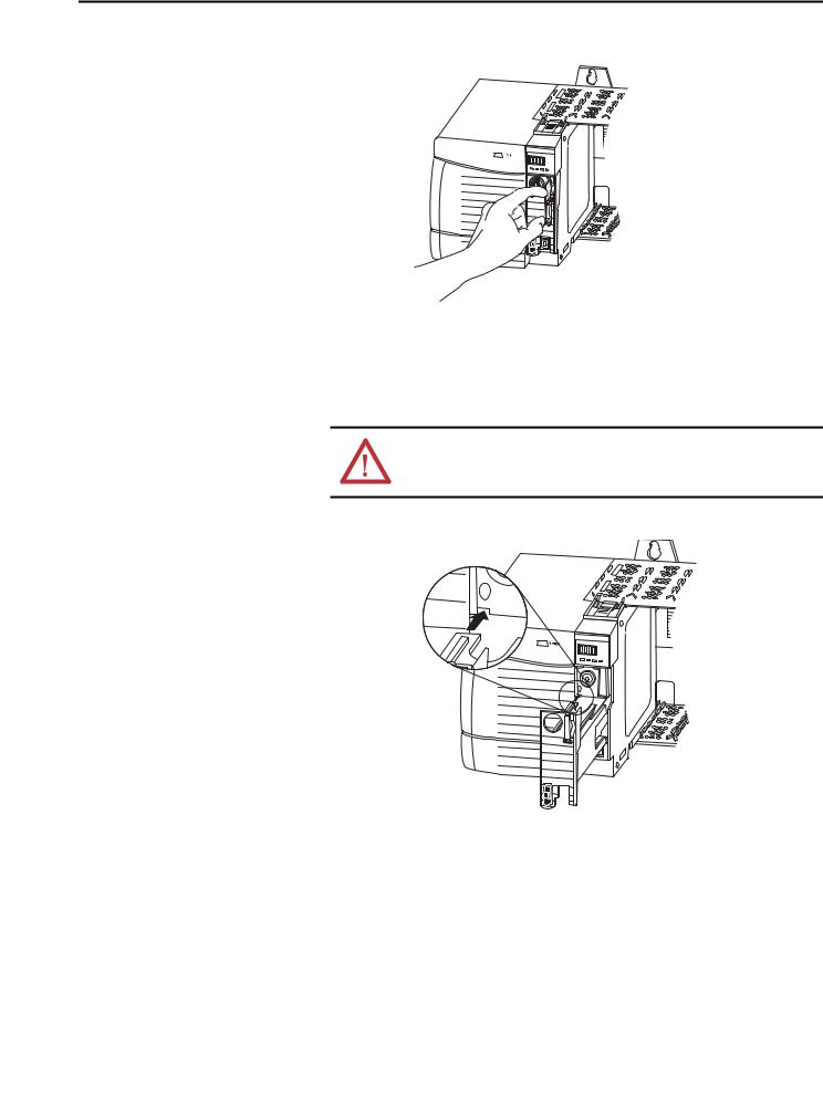
2.Slide the module into the chassis until it snaps into place.
3.Verify that the controller is flush with the power supply or other installed modules.
After you have inserted the controller into the chassis, reference the Troubleshoot the Module on page 183 for information to interpret the status indicators.
Insert the Key |
After the controller is installed, insert the key. |
Logix 55xx
RUN FORCESD OK
24 |
|
|
|
|
|
|
|
|
|
|
|
|
|
|
|
|
|
|
|
|
|
|
|
|
|
|
|
|
|
|
|
|
|
|
|
|
|
|
|
|
|
|
|
|
|
|
|
|
|
|
|
|
|
|
|
|
|
|
|
|
|
|
Rockwell Automation Publication 1756-UM001O-EN-P - October 2014 |
|
|||||||
Install the 1756-L7x Controller |
Chapter 1 |
|
|
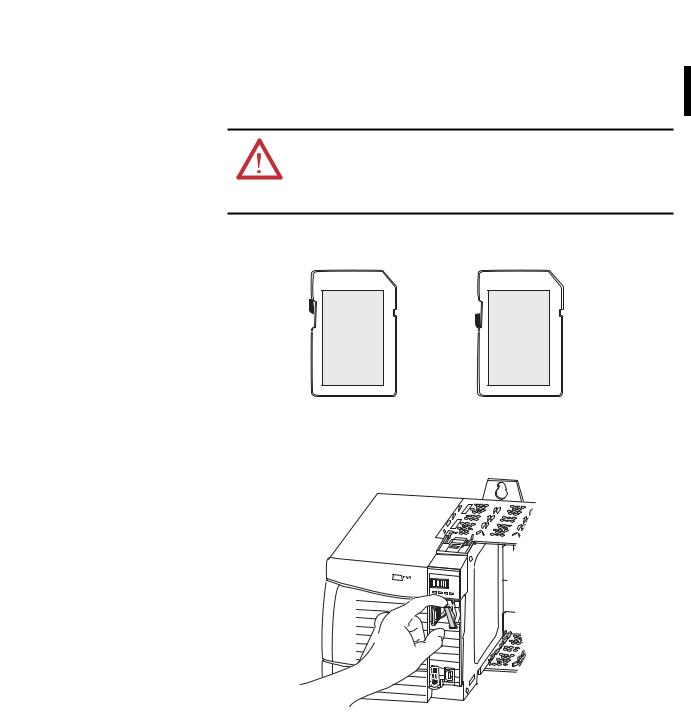
Install the SD Card
Complete these steps to install the SD card in the 1756-L7x controllers.
It is recommended that you leave the SD card in the controller, even when it is not used. If the controller experiences a Major nonrecoverable Fault, extended fault information is saved to the card.
WARNING: When you insert or remove the Secure Digital (SD) memory card while power is on, an electrical arc can occur. This could cause an explosion in hazardous location installations.
Be sure that power is removed or the area is nonhazardous before proceeding.
1. Verify that the SD card is locked or unlocked according to your preference.
Unlocked
Locked
For more information about the lock/unlock memory settings, see the Load or Store to the Memory Card on page 65.
2. Open the door for the SD card.
Logix 55xx
OK
3. Insert the SD card into the SD card slot.
Rockwell Automation Publication 1756-UM001O-EN-P - October 2014 |
25 |

Chapter 1 Install the 1756-L7x Controller
4. Gently press the card until it clicks into place.
Logix 55xx
RUN FORCESD OK
5. Close the SD card door.
Logix 55xx
RUN FORCESD OK
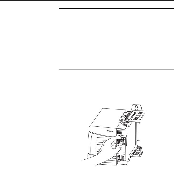
Remove the SD Card
The 1756-L7x controller ships with an SD card installed. Complete these steps to remove the SD card from the 1756-L7x controller.
WARNING: When you insert or remove the Secure Digital (SD) memory card while power is on, an electrical arc can occur. This could cause an explosion in hazardous location installations.
Be sure that power is removed or the area is nonhazardous before proceeding.
26 |
Rockwell Automation Publication 1756-UM001O-EN-P - October 2014 |
Install the 1756-L7x Controller Chapter 1
IMPORTANT |
• Verify that the SD card status indicator is off and that the card is not in use |
|
before removing it. |
|
• We recommend that you do the following: |
|
–Leave an SD card installed. |
|
– Use the SD cards available from Rockwell Automation (catalog number |
|
1784-SD1 or 1784-SD2). |
•While other SD cards can be used with the controller, Rockwell Automation has not tested the use of those cards with the controller. If you use an SD card other than those cards that are available from Rockwell Automation, you can experience data corruption or loss.
•Also, SD cards that are not provided by Rockwell Automation do not have the same industrial, environmental, and certification ratings as those cards that are available from Rockwell Automation.
1.Verify that the SD card is not in use by checking to be sure that the SD indicator is Off.
TIP |
You can also put the controller into Hard Run mode to keep the |
|
controller from writing to the SD card while it is removed. |
2. Open the door to access the SD card.
Logix 55xx
OK
3. Press and release the SD card to eject it.
Rockwell Automation Publication 1756-UM001O-EN-P - October 2014 |
27 |
Chapter 1 Install the 1756-L7x Controller
Install the ESM
Logix 55xx
RUN FORCESD OK
4. Remove the SD card and close the door.
To install an ESM in the 1756-L7x controller, complete these steps.
ATTENTION: To avoid potential damage to the product when inserting the ESM, align it in the track and slide forward with minimal force until the ESM snaps into place.
1. Align the tongue-and-groove slots of the ESM and controller.
Logix 55xx
RUN FORCESD OK
2.Slide the ESM back until it snaps into place.
The ESM begins charging after installation. The following status messages indicate charging status:
•ESM Charging
•CHRG
After you install the ESM, it can take up to 15 seconds for the charging status messages to display.
28 |
Rockwell Automation Publication 1756-UM001O-EN-P - October 2014 |

Install the 1756-L7x Controller |
Chapter 1 |
|
|
Uninstall the ESM
.
IMPORTANT |
Allow the ESM to finish charging before removing power from the controller. |
|
Failure to do so can result in the loss of the application program. A type 1, |
|
code 40 major fault is logged on powerup. |
|
To verify that the ESM is fully charged, check the status display to confirm that |
|
messages CHRG or ESM charging are no longer indicated. |
|
|
TIP |
We recommend that you check the WallClockTime object attributes after |
|
installing an ESM to verify that time of the controller is correct. |
|
The ESM contains a real-time clock. If the ESM is new or came from another |
|
controller, the WallClockTime object attributes for your controller can change. |
WARNING: If your application requires the ESM to deplete its residual stored energy to 40 μJoule or less before you transport it into or out of the application, use only the 1756-(SP)ESMNSE(XT) module. In this case, complete these steps before you remove the ESM.
• Turn power off to the chassis.
After you turn power off to the chassis, the controller’s OK status indicator transitions from green to solid red to OFF.
•Wait at least 20 minutes for the residual stored energy to decrease to 40 μJoule or less before you remove the ESM.
There is no visual indication of when the 20 minutes has expired. You must track that time period.
WARNING: When you insert or remove the energy storage module while backplane power is on, an electrical arc can occur. This could cause an explosion in hazardous location installations.
Be sure that power is removed or the area is nonhazardous before proceeding. Repeated electrical arcing causes excessive wear to contacts on both the module and its mating connector.
IMPORTANT |
Before you remove an ESM, make necessary adjustments to your program |
|
to account for potential changes to the WallClockTime attribute. |
|
|
Consider these points before removing the ESM:
•The following ESM modules can be currently installed in your 1756-L7x or 1756-L7xXT controller:
–1756-ESMCAP
–1756-ESMNSE
–1756-ESMCAPXT
–1756-ESMNSEXT
Rockwell Automation Publication 1756-UM001O-EN-P - October 2014 |
29 |

Chapter 1 Install the 1756-L7x Controller
•The 1756-L7x controllers come with the 1756-ESMCAP module installed. The 1756-L7xXT extreme temperature controller ships with a 1756-ESMCAPXT module installed. For more information on how to use a 1756-ESMNSE, 1756-ESMNRM, 1756-ESMNSEXT, or 1756-ESMNRMXT module, see page 28.
•After the 1756-L7x or 1756-L7xXT controllers lose power, because the chassis power is turned off or the controller has been removed from a powered chassis, do not immediately remove the ESM.
Wait until the OK status indicator on the controller transitions from Green to Solid Red to OFF before you remove the ESM.
•You can use the 1756-ESMNSE module with only a 1756-L73 (8 MB) or smaller memory-sized controller.
•Use the 1756-ESMNSE module if your application requires that the installed ESM deplete its residual stored energy to 40 μJoule or less before transporting it into or out of your application.
•Once it is installed, you cannot remove the 1756-ESMNRM or 1756-ESMNRMXT module from a 1756-L7x or 1756-L7xXT controller.
Complete these steps to remove an ESM module from the controller.
1. Remove the key from the mode switch.
IMPORTANT |
The next step depends on which of the following conditions applies to your |
|
application. |
|
• If you are removing the ESM from a powered 1756-L7x controller, go to |
|
step 2. |
|
• If you are removing the ESM from a 1756-L7x controller that is not |
|
powered, because the chassis power is turned off or the controller has |
|
been removed from a powered chassis, do not immediately remove |
|
the ESM. |
|
Wait until the OK status indicator on the controller transitions from Green to |
|
Solid Red to OFF before you remove the ESM. |
|
After the OK status indicator transitions to Off, go to step 2. |
|
|
30 |
Rockwell Automation Publication 1756-UM001O-EN-P - October 2014 |
Loading...