


 Loading...
Very High-Speed
Counter Modules
1734-VHSC5 and 1734-VHSC24
User Manual
Important User Information Solid state equipment has operational characteristics differing from those of electromechanical equipment. Safety Guidelines for the Application,
Installation and Maintenance of Solid State Controls (Publication SGI-1.1 available from your local Rockwell Automation sales office or online at http://literature.rockwellautomation.com) describes some important differences between solid state equipment and hard-wired electromechanical devices. Because of this difference, and also because of the wide variety of uses for solid state equipment, all persons responsible for applying this equipment must satisfy themselves that each intended application of this equipment is acceptable.
In no event will Rockwell Automation, Inc. be responsible or liable for indirect or consequential damages resulting from the use or application of this equipment.
The examples and diagrams in this manual are included solely for illustrative purposes. Because of the many variables and requirements associated with any particular installation, Rockwell Automation, Inc. cannot assume responsibility or liability for actual use based on the examples and diagrams.
No patent liability is assumed by Rockwell Automation, Inc. with respect to use of information, circuits, equipment, or software described in this manual.
Reproduction of the contents of this manual, in whole or in part, without written permission of Rockwell Automation, Inc., is prohibited.
Throughout this manual, when necessary we use notes to make you aware of safety considerations.
WARNING
Identifies information about practices or circumstances that can cause an explosion in a hazardous environment, which may lead to personal injury or death, property damage, or economic loss.
IMPORTANT
Identifies information that is critical for successful application and understanding of the product.
ATTENTION
Identifies information about practices or circumstances that can lead to personal injury or death, property damage, or economic loss. Attentions help you:
• identify a hazard
• avoid a hazard
• recognize the consequence
SHOCK HAZARD |
Labels may be located on or inside the equipment (for |
||||
|
|
|
|
|
example, drive or motor) to alert people that dangerous |
|
|
|
|
|
voltage may be present. |
|
|
|
|
||
|
|
|
|
|
|
|
|
||||
|
|
|
|
|
|
|
|
|
|
|
Labels may be located on or inside the equipment (for |
BURN HAZARD |
|||||
|
|
|
|
|
example, drive or motor) to alert people that surfaces may |
|
|
|
|
|
be dangerous temperatures. |
|
|
|
|
|
|
|
|
|
|
|
|
POINT I/O, POINTBus, and RSLogix 5000 are trademarks of Rockwell Automation.
ControlNet is a trademark of ControlNet International, Ltd. DeviceNet is a trademark of Open DeviceNet Vendor Association, Inc.

Summary of Changes
Summary of Changes
This publication contains new and revised information not in the last release.
New and Revised Information
See the table for a summary of the major changes in this manual.
Chapter |
Change |
|
|
Preface |
Update of list of publications |
|
Indication that for specifications and safety approval information |
|
refer to the installation instructions |
|
|
2 |
Addition of Before You Begin section |
|
Addition of attention and warning statements |
|
|
Appendix A |
Update on how to configure modules in RSLogix 5000 software |
|
|
Change Bars
We marked with change bars (as shown with this paragraph) the areas in this manual that differ from previous editions and indicate the addition of new or revised information.
Publication 1734-UM003B-EN-P - August 2005

Summary of Changes |
2 |
|
|
Notes:
Publication 1734-UM003B-EN-P - August 2005

|
Table of Contents |
|
|
Preface |
|
Preface |
Purpose of This Manual. . . . . . . . . . . . . . . . . . . . . . . . . . . |
P-1 |
|
Who Should Use This Manual . . . . . . . . . . . . . . . . . . . . . . |
P-1 |
|
Related Products and Documentation. . . . . . . . . . . . . . . . . |
P-1 |
|
Definitions . . . . . . . . . . . . . . . . . . . . . . . . . . . . . . . . . . . . |
P-3 |
|
Chapter 1 |
|
About the Modules |
What This Chapter Contains . . . . . . . . . . . . . . . . . . . . . . . |
1-1 |
|
Operating Modes . . . . . . . . . . . . . . . . . . . . . . . . . . . . . . . |
1-2 |
|
Counter Mode . . . . . . . . . . . . . . . . . . . . . . . . . . . . . . . |
1-2 |
|
Encoder Modes . . . . . . . . . . . . . . . . . . . . . . . . . . . . . . |
1-3 |
|
Period/Rate Mode . . . . . . . . . . . . . . . . . . . . . . . . . . . . |
1-5 |
|
Operation of Scalar . . . . . . . . . . . . . . . . . . . . . . . . . . . |
1-6 |
|
Rate Measurement Mode . . . . . . . . . . . . . . . . . . . . . . . |
1-7 |
|
New Data Indicator . . . . . . . . . . . . . . . . . . . . . . . . . . . |
1-8 |
|
Default Configuration. . . . . . . . . . . . . . . . . . . . . . . . . . |
1-8 |
|
Operating Mode Features . . . . . . . . . . . . . . . . . . . . . . . . . |
1-9 |
|
Chapter 2 |
|
Install the Modules |
What This Chapter Contains . . . . . . . . . . . . . . . . . . . . . . . |
2-1 |
|
Before You Begin . . . . . . . . . . . . . . . . . . . . . . . . . . . . . . . |
2-1 |
|
Install the Mounting Base Assembly . . . . . . . . . . . . . . . . . . |
2-1 |
|
Install an I/O Module . . . . . . . . . . . . . . . . . . . . . . . . . . . . |
2-2 |
|
Install the Removable Terminal Block . . . . . . . . . . . . . . . . |
2-4 |
|
Remove a Mounting Base . . . . . . . . . . . . . . . . . . . . . . . . . |
2-4 |
|
Wire the Modules . . . . . . . . . . . . . . . . . . . . . . . . . . . . . . . |
2-5 |
|
Chapter 3 |
|
Input and Output Data |
What This Chapter Contains . . . . . . . . . . . . . . . . . . . . . . . |
3-1 |
|
Data Table . . . . . . . . . . . . . . . . . . . . . . . . . . . . . . . . . . . . |
3-1 |
|
Detailed Description of Data Table Information . . . . . . . . . |
3-2 |
|
Stored/Accumulated Channel Data (Input Word 2) . . . . |
3-2 |
|
Module/Channel Status and Programming Error Codes |
|
|
(Input Words 3 and 4) . . . . . . . . . . . . . . . . . . . . . . . . . |
3-2 |
Publication 1734-UM003B-EN-P - August 2005
|
Configuration Data . . . . . . . . . . . . . . . . . . . . . . . . . . . . . . |
3-4 |
|
Counter Configuration (Configuration Word 1) . . . . . . . |
3-5 |
|
Filter Selection (Configuration Word 2 . . . . . . . . . . . . . |
3-5 |
|
Decimal Position (Configuration Word 3) . . . . . . . . . . . |
3-6 |
|
Word 4 is reserved. . . . . . . . . . . . . . . . . . . . . . . . . . . . |
3-6 |
|
Time Base and Gate Interval (Configuration Words |
|
|
5 and 6) . . . . . . . . . . . . . . . . . . . . . . . . . . . . . . . . . . . |
3-6 |
|
Scalar (Configuration Word 7) . . . . . . . . . . . . . . . . . . . |
3-7 |
|
Scalar Selection . . . . . . . . . . . . . . . . . . . . . . . . . . . . . . |
3-7 |
|
Rollover (Configuration Word 8). . . . . . . . . . . . . . . . . . |
3-7 |
|
Preset (Configuration Word 9) . . . . . . . . . . . . . . . . . . . |
3-7 |
|
Safe State Values (Configuration Word 10) . . . . . . . . . . |
3-8 |
|
Communicate Real Time and Nonreal Time Information . . . |
3-8 |
|
Chapter 4 |
|
Configure Your Module |
What This Chapter Contains . . . . . . . . . . . . . . . . . . . . . . . |
4-1 |
|
Configuration Overview . . . . . . . . . . . . . . . . . . . . . . . . . . |
4-1 |
|
Add the Adapter to Your Network . . . . . . . . . . . . . . . . |
4-1 |
|
Add I/O Modules to Your Network. . . . . . . . . . . . . . . . |
4-2 |
|
Set Counter Parameters . . . . . . . . . . . . . . . . . . . . . . . . . . . |
4-4 |
|
Check I/O Status and View/Edit the EDS File . . . . . . . . . . . |
4-6 |
|
Chapter 5 |
|
Access Instantiated Instances |
What This Chapter Contains . . . . . . . . . . . . . . . . . . . . . . . |
5-1 |
|
Use Instantiated Instances . . . . . . . . . . . . . . . . . . . . . . . . . |
5-1 |
|
Assemblies . . . . . . . . . . . . . . . . . . . . . . . . . . . . . . . . . . . . |
5-3 |
Chapter 6
Troubleshoot with the Indicators
Configure Modules in
RSLogix 5000
Use the Indicators for Troubleshooting . . . . . . . . . . . . . . . 6-1
Appendix A
What This Appendix Contains . . . . . . . . . . . . . . . . . . . . . . A-1
Understand Data, Connection, and Communication Formats A-1 Configure Your Module. . . . . . . . . . . . . . . . . . . . . . . . . . . A-3 Use the Help Button . . . . . . . . . . . . . . . . . . . . . . . . . . . . . A-3 Work with the Fault/Program Action Dialog. . . . . . . . . . . . A-4 Work with the Counter Configuration Dialog . . . . . . . . . . . A-6 Work with the Output Configuration Dialog. . . . . . . . . . . A-10
Index
Publication 1734-UM003B-EN-P - August 2005

Preface
Purpose of This Manual
Read this manual for information about how to install, configure, and troubleshoot your module.
Who Should Use This
Manual
For This Information |
See |
|
|
About the Modules |
Chapter 1 |
|
|
Install the Modules |
Chapter 2 |
|
|
Input and Output Data |
Chapter 3 |
|
|
Configure Your Module |
Chapter 4 |
|
|
Access Instantiated Instances |
Chapter 5 |
|
|
Troubleshoot with the Indicators |
Chapter 6 |
|
|
You must be able to use RSNetWorx software or similar configuration software to set up and calibrate these modules. You must have the capability to download and use Electronic Data Sheet files.
We assume you know how to do this in this manual. If you do not, refer to your software user manuals or online help before attempting to use these modules.
Publication 1734-UM003B-EN-P - August 2005

Preface 2
Related Products and
Documentation
For specification, safety approval, and other information refer to the following.
•Publication Number 1734-IN003
5V and 24V Very High-speed Counter Modules Installation Instructions
For related 1734 products and documentation see the table.
Description |
Cat. No. |
Publication |
|
|
|
Analog Input Modules |
1734-IE2C |
1734-IN027 |
Installation Instructions |
17340IE2V |
|
|
|
|
Analog Output Modules |
1734-OE2C |
1734-IN002 |
Installation Instructions |
1734-OE2V |
|
|
|
|
DeviceNet Communication Interface |
1734-PDN |
1734-IN057 |
Installation Instructions |
|
|
|
|
|
Field Potential Distributor |
1734-FPD |
1734-IN059 |
Installation Instructions |
|
|
|
|
|
POINT I/O 24V dc Expansion Power Supply |
1734-EP24DC |
1734-IN058 |
Installation Instructions |
|
|
|
|
|
POINT I/O Selection Guide |
1734 series |
1734-SG001 |
|
|
|
Protected Output Module s |
1734-OB2E |
1734-IN056 |
Installation Instructions |
1734-OB4E |
|
|
1734-OB8E |
|
|
|
|
Relay Output Modules |
1734-OW2 |
1734-IN055 |
Installation Instructions |
1734-OW4 |
|
|
|
|
Sink Input Modules |
1734-IB2 |
1734-IN051 |
Installation Instructions |
1734-IB4 |
|
|
1734-IB8 |
|
|
|
|
Source Output Modules |
1734-IV2 |
1734-IN052 |
Installation Instructions |
1734-IV4 |
|
|
1734-IV8 |
|
|
|
|
Wiring Base Assembly |
1734-TB |
1734-IN511 |
Installation Instructions |
1734-TBS |
|
|
|
|
Wiring Base Assembly |
1734-TB3 |
1734-IN013 |
Installation Instructions |
1734-TB3S |
|
|
|
|
Publication 1734-UM003B-EN-P - August 2005

Preface 3
Definitions
The following define the intended operation of the module.
Term |
Definition |
|
|
Lead Breakage |
Typically requires a shunt resistor (across the load) to detect |
|
3 levels of current/input states - |
|
• Open (Wire Off, Device = ?) |
|
• Off (Wire OK, Device Off) |
|
• On (Wire OK, Device On) |
|
This method does not check the input against a time base, |
|
only that the device wiring (current loop) is intact. |
|
|
Missing Pulse |
Typically uses an input pulse to reset a watchdog timer (fixed |
|
or programmable HW). This method does detect Lead |
|
Breakage, since a broken wire will time-out the watchdog. |
|
|
Zero Frequency |
Typically uses an input pulse to calculate an input frequency |
|
and verify it is above an error threshold. This method does |
|
detect Lead Breakage, since a broken wire will generate a |
|
0Hz frequency. |
|
Missing Pulse or Zero Frequency will also detect a customer |
|
device stuck high or low, since the counter is monitoring for a |
|
change in the input state. Currently, the Counter/Encoder |
|
Modes do not have Zero Frequency Detection - the A and B |
|
inputs are time independent, only looking for input edge |
|
changes to increment/decrement the count value. |
|
The Period/Rate and Continuous Rate modes do have Zero |
|
Frequency Detection, since the Z input is monitored for Zero |
|
Frequency in Firmware (A and B inputs are not used and not |
|
monitored). |
|
The Rate Measurement mode inherently has Zero Frequency |
|
Detection, since no A pulses in any sample period are = 0Hz |
|
(B and Z inputs are not used and not monitored). |
|
|
Publication 1734-UM003B-EN-P - August 2005

Preface 4
Operational Mode |
Zero Frequency Detection |
Input Monitored |
|
|
|
Counter |
No |
None |
|
|
|
Encoder |
No |
None |
|
|
|
Period/Rate |
Yes |
Z Only |
|
|
|
Rate Measurement |
Y |
A Only |
|
|
|
Publication 1734-UM003B-EN-P - August 2005
Chapter 1
About the Modules
What This Chapter Contains
Module Description and
Features
Read this chapter to learn about types, features, and capabilities of the encoder/counter modules.
The modules install into the POINT I/O terminal base (1734-TB or 1734-TBS) and interface with the Point I/O DeviceNet Pass-through (1734-PDN) or the Point I/O DeviceNet Adapter (1734-ADN).
A module serves as a signal conditioner, function block, and counter between the customer process signals on the terminal base and the POINTBus containing the command information. The main functional blocks are the following.
•Customer digital I/O interface
•Counter ASIC
•Microprocessor
The module accepts feedback from the following.
•Encoders (either single ended or differential)
•Pulse generators
•Mechanical limit switches
•Frequencies up to 1 MHz
A filter is available with the following settings.
•50 Hz
•500 Hz
•5 kHz
•50 kHz)
Turn the filter off to achieve the fastest counting rate. The input voltage range is 5Vdc (VHSC5) or 15-24V dc (VHSC24). The module returns the count or frequency in the form of a 24 bit binary number (0 - 16,777,215) expressed in a 32 bit long word.
Each counter has a user-selectable preset and rollover value associated with it.
The module has 2 outputs that access customer power from the POINTBus to facilitate various output device voltage requirements.
Publication 1734-UM003B-EN-P - August 2005

1-2 About the Modules
Operating Modes
The outputs are rated to source 0.5A at 10 to 28.8V dc. The output may be tied to an input. This lets you cascade counters of multiple 1734-VHSC modules. The counter has 4 user-selectable On-Off values (windows) associated with it. Tie either output to any or all of the window signals.
The modules operate in the modes shown in the table.
Mode |
Description |
|
|
Counter Mode |
Read read incoming single-phase pulses, return a |
|
binary count. |
|
|
Encoder Mode |
Read incoming two-phase quadrature pulses, return |
|
a binary count. |
|
|
Period/Rate Mode |
Count internal clocks during the On period, return a |
|
frequency. Outputs updated only at the end of the |
|
period. |
|
|
Continuous/Rate Mode |
Count internal clocks during the On period, return a |
|
frequency. Outputs are updated continuously during |
|
the period. |
|
|
Rate Measurement Mode |
Read pulses during the sample period, return a |
|
frequency. |
|
|
PWM Mode (pulse width |
Generate a pulse width modulated signal. |
modulation) |
|
|
|
The operation of the counter and encoder modes is nearly identical. The difference between the two modes is in the type of feedback (single-phase versus two-phase) for the count direction (up or down). In encoder mode, a transition is expected on the B input for counting to proceed in a direction; whereas, in counter mode, the B input may be left at a static level.
You select all operating modes by writing appropriate configuration data to the module.
Counter Mode
The counter mode reads incoming pulses and returns a binary number (0 - 16,777,215max) to the POINTBus. The counter mode only accepts single-phase inputs. The module determines the Phase B input state, and counts up or down accordingly.
Publication 1734-UM003B-EN-P - August 2005
About the Modules |
1-3 |
|
|
Channel A input is used as the counting pulse while channel B is used to determine the direction.
[B = High, Count = Down; B = Low or floating (not connected), Count = Up]
The Channel B input may be tied high or low for unidirectional counting, or toggled for bidirectional counting.
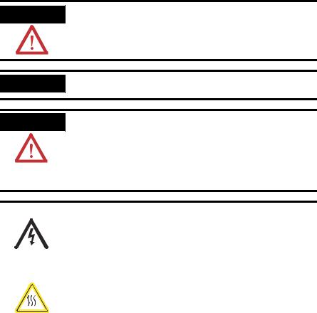
EXAMPLE
Example of Counter Mode
|
|
|
|
A |
Input |
Input A |
|
|
|
|
B |
Direction |
|
|
|
|
|
Input B |
||
|
|
|
||||
|
|
|
|
Z (Store Count) |
||
|
|
|
|
|||
|
|
|
|
Input Z |
||
|
|
|
|
(Gate / Reset ) |
||
|
|
|
|
|||
|
|
|
|
|
||
Single Phase Pulse Generator |
|
|
||||
|
1734-VHSC |
|||||
|
|
|
|
|
|
|
|
|
|
Count Up |
Count Down |
||
A Input
B Input
Outputs
Count Updated
Continuously
0 |
1 |
2 |
3 |
2 |
1 |
0 |
Encoder Modes
The encoder mode reads incoming pulses and returns a binary number (0 - 16,777,215max) to the POINTBus. The encoder mode only accepts two-phase quadrature inputs. The module senses the relationship between the 2 phases, and counts up or down accordingly.
There are two basic encoder types, absolute and incremental. A single-output incremental encoder is called a tachometer encoder. A dual channel incremental encoder with one channel leading the other by 90° is called a quadrature encoder.
A system using a quadrature encoder may include an optional zero pulse, or index, serving as a reference mark for system reset. The principal disadvantage of a system using incremental encoders is that a power interruption causes the loss of position reference, so a system must be reinitialized or returned to a known zero position.
Publication 1734-UM003B-EN-P - August 2005
1-4 About the Modules
Absolute encoders typically have higher speed requirements (200 KHz typical) for motion control applications. An absolute encoder has a unique code associated with each position, so the exact position is always known, even if the system power is turned off.
EXAMPLE
Example of Multiplying Encoder Mode X1, X2 and X4
|
|
|
|
|
|
|
|
|
|
|
|
|
|
|
|
|
|
|
|
|
A |
|
|
|
|
|
|
|
|
|
|
|
|
Input A |
|
|
|
|
|
|
|
|
|
|
|
|
|
|
|
|
|
|
|
|
|
|
B |
|
|
|
|
|
|
|
|
|
|
|
|
|
|
|
|
|
|
|
|
|
|
|
|
|
|
|
|
|
|
|
|
|
|
|
|
|
|
|
|
|
|
|
|
|
|
|
Input B |
|
|
|
|
|
|
|
|
|
|
|
|
|
|
|
|
|
|
|
|
|
|
|
|
|
|
|
|
|
|
|
|
|
|
|
|
||
|
|
|
|
|
|
|
|
|
|
|
|
|
|
|
|
|
|
|
|
|
Z |
(Store Count) |
|
|
|
|
|
|
|
||||||
|
|
|
|
|
|
|
|
|
|
|
|
|
|
|
|
|
|
|
|
|
|
|
|
|
|
|
|
||||||||
|
|
|
|
|
|
|
|
|
|
|
|
|
|
|
|
|
|
|
|
|
|
|
|
|
|
|
Input Z |
|
|||||||
|
|
|
|
|
|
|
|
|
|
|
|
|
|
|
|
|
|
|
|
|
(Gate / Reset ) |
|
|
|
|
|
|
|
|||||||
Quadrature Encoder |
|
|
|
|
|
|
|
|
|
|
|
|
|
|
|
|
|
||||||||||||||||||
|
|
|
|
|
|
|
|
|
|
|
|
|
|
|
|
|
|
||||||||||||||||||
|
|
|
|
|
|
|
|
|
|
|
|
|
|
|
|
|
|
|
|
|
|
|
|
|
|||||||||||
|
|
|
|
|
|
|
|
|
|
|
|
|
|
|
|
|
|
|
|
|
|
|
1734-VHSC |
||||||||||||
|
|
|
|
|
|
|
|
|
|
|
|
|
|
|
|
|
|
|
|
|
|
|
|
|
|
|
|
|
|
|
|
|
|
||
|
|
|
|
|
|
|
|
Forward Rotation |
|
|
|
|
|
|
Reverse Rotation |
|
|
|
|
|
|||||||||||||||
A Input |
|
|
|
|
|
|
|
|
|
|
|
|
|
|
|
|
|
|
|
|
|
|
|
|
|
|
|
|
|
|
|||||
|
|
|
|
|
|
|
|
|
|
|
|
|
|
|
|
|
|
|
|
|
|
|
|
|
|
|
|
|
|
||||||
B Input |
|
|
|
|
|
|
|
|
|
|
|
|
|
|
|
|
|
|
|
|
|
|
|
|
|
|
|
|
|
|
|||||
1 |
|
|
|
|
2 |
|
|
|
|
3 |
|
|
|
|
|
|
|
|
2 |
|
|
|
1 |
|
|
|
0 |
|
|
||||||
|
|
|
|
|
|
|
|
|
|
|
|
|
|
|
|
|
|
|
|
|
|
|
|
|
|||||||||||
X1 Count |
|
|
|
|
|
|
|
|
|
|
|
|
|
|
|
|
|
|
|
|
|
|
|
|
|
|
|
|
|
|
|
||||
|
|
|
|
|
|
|
|
|
|
|
|
|
|
|
|
|
|
|
|
|
|
|
|
|
|
|
|
|
|
|
|||||
|
1 |
|
|
2 |
|
3 |
|
|
4 |
|
5 |
|
|
6 |
|
|
|
5 |
|
4 |
|
3 |
|
2 |
|
1 |
|
0 |
|
|
|||||
X2 Count |
|
|
|
|
|
|
|
|
|
|
|
|
|
|
|
|
|
|
|
|
|
|
|
|
|
|
|
|
Outputs |
||||||
|
|
|
|
|
|
|
|
|
|
|
|
|
|
|
|
|
|
|
|
|
|
|
|
|
|
|
|||||||||
|
|
|
|
|
|
|
|
|
|
|
|
|
|
|
|
|
|
|
|
|
|
|
|
|
|
|
|
|
|
|
|
|
|
||
|
|
|
|
|
|
|
|
|
|
|
|
|
|
|
|
|
|
|
|
|
|
|
|
|
|
|
|
|
|
|
|
|
|
||
|
1 |
|
2 |
3 |
4 |
5 |
|
6 |
7 |
8 |
9 |
|
10 |
11 |
12 |
11 |
10 |
9 |
8 |
7 |
6 |
5 |
4 |
3 |
2 |
1 |
0 |
Updated |
|||||||
X4 Count |
|
|
|
|
|
|
|
|
|
|
|
|
|
|
|
|
|
|
|
|
|
|
|
|
|
|
|
|
Continuously |
||||||
|
|
|
|
|
|
|
|
|
|
|
|
|
|
|
|
|
|
|
|
|
|
|
|
|
|
|
|
|
|
|
|
|
|
|
|
X1 Multiplying Encoder Mode
Quadrature input signals are used to count on the leading (up direction) or trailing (down direction) edge of A for a bidirectional count, and channel B is used to determine the direction.
[ B = leads A, Count = Down; B = follows A, Count = Up ]
X2 Multiplying Encoder Mode
Quadrature input signals are used to count on leading and trailing edges of A for a bidirectional count, and channel B is used to determine the direction.
[ B = leads A, Count = Down; B = follows A, Count = Up ]
Publication 1734-UM003B-EN-P - August 2005
About the Modules |
1-5 |
|
|
X4 Multiplying Encoder Mode
Quadrature input signals are used to count on leading and trailing edges of A and B for a bidirectional count, and channel B is used to determine the direction.
[ B = leads A, Count = Down; B = follows A, Count = Up ]
Period/Rate Mode
The Period/Rate mode returns an incoming frequency and a total accumulated count to the POINTBus, by gating an internal 5 MHz internal clock with an external signal.
This mode determines the frequency and total number of input pulses by counting the number of internal 5MHz clock pulses over a user-specified number of input signal pulses. At the end of the specified number of pulses, the module returns the frequency
(0 - 1 MHz). When the frequency is updated, both outputs are checked against their associated presets.
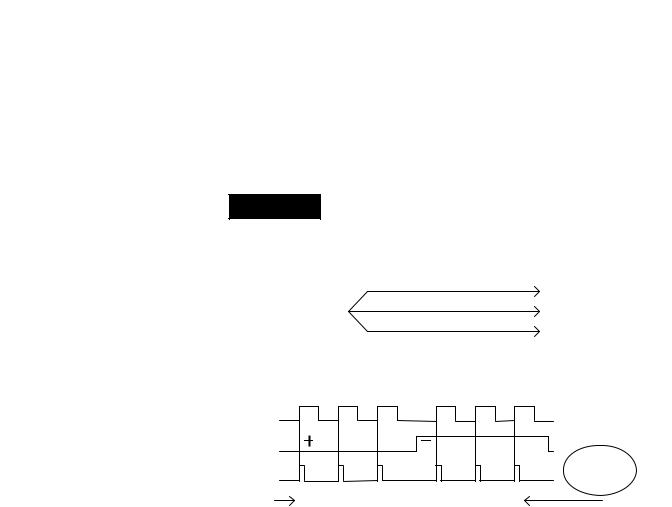
EXAMPLE
Example of Period/Rate Mode
|
|
A ( Not Used ) |
|
Input A |
|
|
B ( Not Used ) |
|
|
|
|
|
Input B |
|
|
|
Z |
|
|
|
|
|
Input Z |
|
|
|
(Gate / Reset ) |
|
|
Encoder / Pulse Generator |
|
Scalar |
||
|
|
|||
|
|
|
|
5 MHz Clk |
|
|
|
1734-VHSC |
|
Z Input ( Pulse ) |
|
|
|
|
5 MHz Internal |
|
|
|
|
Sampling Clock |
1 |
10 |
20 |
Frequency & Outputs |
|
||||
|
|
|
|
|
Accumulated Count |
|
|
|
Updated Here |
|
|
|
|
|
Assumes symmetrical pulse, 50% duty cycle, so Period = Sample Time On X 2 {On & Off}
Frequency = 1 / Period If Count = 20, Scalar = 1, and Clock Period = ( 1 / 5 MHz )
Frequency = 1 / [ ( 20 / 1 ) X ( 1 / 5 MHz ) X 2 ] = 125 kHz
Publication 1734-UM003B-EN-P - August 2005

1-6 About the Modules
As the frequency of the incoming pulse train at the Z (Gate/Reset) terminal increases, the number of sampled pulses from the 5MHz clock decreases. Since accuracy is related to the number of pulses received over the sample period, the accuracy decreases with increasing frequencies at the Gate/Reset terminal. Refer to the following Scaling table.
Relationship Between Sampled Pulses and Input Frequency
Input Frequency at Z Gate/Reset Terminal |
Sample Pulses for 1/2 Cycle of Z Gate/Reset Pulse |
|
|
2.5 Hz |
1 M |
|
|
5 Hz |
500 k |
|
|
10 Hz |
250 k |
|
|
20 Hz |
125 k |
|
|
50 Hz |
50 k |
|
|
100 Hz |
25 k |
|
|
200 Hz |
12.5 |
|
|
500 Hz |
5 k |
|
|
1k Hz |
2.5 k |
|
|
2 Hz |
1.25 k |
|
|
5 kHz |
500 |
|
|
10 kHz |
250 |
|
|
20 kHz |
125 |
|
|
50 kHz |
50 |
|
|
100 kHz |
25 |
|
|
Scaling the input frequency through the use of a scalar can lessen the decrease in accuracy. A scalar value of 1 returns an accurate input frequency if incoming input pulses have a 50% duty cycle.
Operation of Scalar
In the Period/Rate mode, the scalar lets the incoming pulse train at the Z Gate/Reset pin be divided by a user-defined number. There is one scalar value for each counter. Acceptable values for the scalar are 1, 2, 4, 8, 16, 32, 64, and 128. The default value for each scalar is 1.
Note that a 0 scalar is equivalent to a 1.
The product of the Sample Period times the scalar should be less than 6.71 seconds in order to avoid a zero frequency detect indication.
(5 MHz sample time = 200ns; 16,777,216 counts x 200ns x 2 half cycles of Z = 6.71 seconds)
Publication 1734-UM003B-EN-P - August 2005
About the Modules |
1-7 |
|
|
Continuous/Rate Mode
The Continuous/Rate Mode returns an incoming frequency and a total accumulated count to POINTBus, by gating an internal 5 MHz internal clock with an external signal.
Similar to the Period/Rate mode except outputs in this mode are updated continuously. This mode determines the frequency and total number of input pulses by counting the number of internal 5 MHz clock pulses over a user-specified number of input signal pulses. Each output is turned on as soon as the turn-on count is reached, and turned off as soon as the turn-off count is reached. As the internal 5 MHz clock is counted, the outputs dynamically track the 5 MHz count.
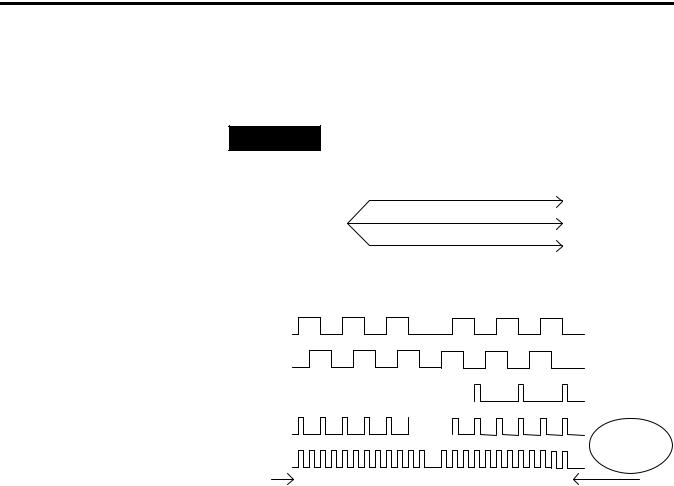
EXAMPLE
Example of Continuous/Rate Mode
|
|
|
|
A ( Not Used ) |
|
|
|
|
Input A |
|
|
|
|
B ( Not Used ) |
|
|
|
|
Input B |
|
|
|
|
|
|
|
|
|
Z |
|
|
|
|
|
|
|
|
|
Input Z |
|
|
|
|
|
Encoder / Pulse Generator |
(Gate / Reset ) |
|||
Scalar |
||||
5 MHz Clk
1734-VHSC
Z Input ( Pulse )
Frequency
5 MHz Internal Updated Here
Sampling Clock
1 |
10 |
20 |
Accumulated Count |
|
Outputs Updated |
|
|
Continuously |
Assumes symmetrical pulse, 50% duty cycle, so Period = Sample Time On X 2 {On &Off}
Frequency = 1 / Period If Count = 20, Scalar = 1, and Clock Period = ( 1 / 5 MHz )
Frequency = 1 / [ ( 20 / 1 ) X ( 1 / 5 MHz ) X 2 ] = 125 kHz
As the frequency of the incoming pulse train at the Z Gate/Reset terminal increases, the number of sampled pulses from the 5 MHz clock decreases. Since accuracy is related to the number of pulses received over the sample period, the accuracy decreases with increasing frequencies at the Gate/Reset terminal. (Refer to the “Operation of Scalar” information and table in the Period/Rate Mode.)
Publication 1734-UM003B-EN-P - August 2005

1-8 About the Modules
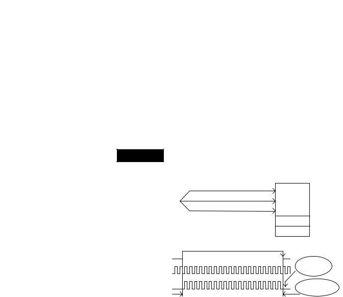
Rate Measurement Mode
The Rate Measurement mode determines the frequency and total number of input pulses over a user-specified sample period. At the end of the interval, the module returns a value representing the sampled number of pulses and a value indicating the incoming frequency.
When you update the count and frequency, you check any associated outputs against their associated presets. Frequency is calculated by dividing the accumulated count by the user-selected time period, and is returned in the read data. Allowable time periods are 10 ms to 3 s in 10 ms increments, with a default value of 1 s. Note that a 0 time period is equivalent to the 1 s default.
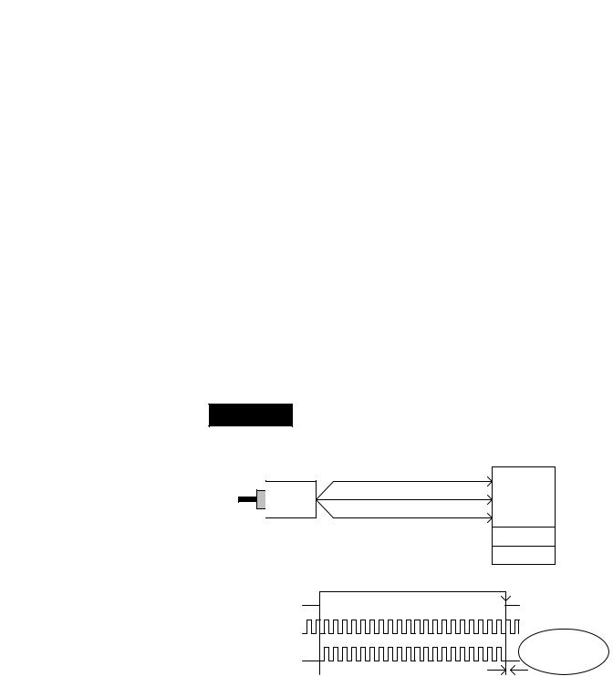
EXAMPLE
Example of Rate Measurement Mode
|
|
|
|
|
A Input |
Input A |
|
|
|
|
|
|
B ( Not Used ) |
||
|
|
|
|
|
Input B |
||
|
|
|
|
|
|||
|
|
|
|
|
Z ( Not Used ) |
||
|
|
|
|
|
|||
|
|
|
|
|
Input Z |
||
|
|
|
|
|
(Gate / Reset ) |
||
Encoder/Pulse Generator |
|||||||
|
|||||||
|
Time Base |
||||||
|
|
|
|
|
|
||
|
|
|
|
|
|
|
|
|
|
|
|
|
|
1734-VHSC |
|
A Input ( Pulse )
Internal Sampling Gate
1 |
2 |
3 |
Accumulated Count
Frequency Calculated,
Outputs Updated Here
User Selectable Sample Period, 10ms to 2s in 10ms increments.
If Sample Period is 50ms, and Count = 3, then Frequency = 3 /50ms = 60Hz
Pulse Width Modulation (PWM) Mode
The Pulse Width Modulation mode uses the counter to generate a continuous rolling sequence of numbers. The real-time PWM value written to the module is converted to a window edge so that a variable duty-cycle signal can be generated. The counter resets to zero based upon the PWM period programmed into the module. Any output tied to Window 0 transmits the PWM signal.
Publication 1734-UM003B-EN-P - August 2005

About the Modules |
1-9 |
|
|
New Data Indicator
A two-bit counter, C1 and C0, is updated every time an event occurs, indicating that new data is available in the Stored/Accumulated Count words. Events are defined as:
Any active gate transition in any of the Store Count (Counter or
Encoder) modes
The end of the gate sample period in either the Period / Rate,
Continuous / Rate or PWM modes
The end of the programmed sample period in the Rate
Measurement mode
To use these bits reliably, acquisition of data from the counter module must occur faster than the events, which cause C1/C0 to increment. When C1/C0 is updated, a change of state (COS) message can be sent.
Default Configuration
The module default configuration on startup are the following.
•Counter mode
•50 Hz filter on A, B, and Z
•No time base
•Active Output Assembly = 105
•Rollover = 0x00FFFFFF
•Preset = 0
•No scalar
•Output 0 untied
•Output 1 untied
•Window comparators = 0
•Counter Control Safe State = 0
•Output Control Safe State = 0
To modify the default settings to those required for your application, refer to the appropriate section of this publication.
Publication 1734-UM003B-EN-P - August 2005

1-10 About the Modules
Operating Mode Features |
See the table for a summary of features active in each mode. |
|||||||
|
|
|
|
|
|
|
|
|
|
Operating Feature |
|
Counter |
Encoder |
Period |
Continuous |
Rate |
PWM |
|
|
|
Up / Down |
X1, X2 & X4 |
/Rate |
/Rate |
Measurement |
|
|
|
|
|
|
|
|
|
|
|
Preset |
|
Y |
Y |
N |
N |
N |
N |
|
|
|
|
|
|
|
|
|
|
Rollover |
|
Y |
Y |
N |
N |
N |
N |
|
|
|
|
|
|
|
|
|
|
Software Reset |
|
Y |
Y |
Y |
Y |
Y |
Y |
|
|
|
|
|
|
|
|
|
|
Store Count - |
|
Y |
Y |
N |
N |
N |
N |
|
Z Gate / Reset |
|
|
|
|
|
|
|
|
4 modes |
|
|
|
|
|
|
|
|
|
|
|
|
|
|
|
|
|
Scale Input Count at |
|
N |
N |
Y |
Y |
N |
N |
|
Z Gate / Reset |
|
|
|
|
|
|
|
|
|
|
|
|
|
|
|
|
|
Z Gate / Reset Invert Bit |
Y |
Y |
Y |
Y |
N |
N |
|
|
|
|
|
|
|
|
|
|
|
Enable /Force Outputs |
|
Y |
Y |
Y |
Y |
Y |
Y |
|
|
|
|
|
|
|
|
|
|
Assign Outputs |
|
Y |
Y |
Y |
Y |
Y |
Y |
|
|
|
|
|
|
|
|
|
|
Operate Outputs |
|
Y |
Y |
Y |
Y |
Y |
Y |
|
(Based On) |
|
(Count) |
(Count) |
(Count) |
(Count) |
(Count) |
(PWM Value) |
|
|
|
|
|
|
|
|
|
|
Sample Period |
|
N |
N |
N |
N |
Y |
Y |
|
|
|
|
|
|
|
|
|
Operating Mode Features
The Z Gate/Reset Terminal operates in one of four modes when the Store Count feature is in use. The four figures below detail the operation in each mode.
Store Count Mode 1: Store/Continue
In mode 1, the rising edge of a pulse input on the Z Gate/Reset terminal causes the current counter value to be read and stored in the Read Data file. The counter continues counting. The stored count is available in the Stored/Accumulated Count word. The stored count information remains until it is overwritten with new data.
Store/Continue
Read, Store Count,
and Continue Counting
Publication 1734-UM003B-EN-P - August 2005
About the Modules |
1-11 |
|
|
Store Count Mode 2: Store/Wait/Resume
In mode 2, the rising edge of a pulse input on the Z Gate/Reset terminal reads and stores the current counter value in the Stored/Accumulated Count word and inhibit counting while the Z Gate/Reset terminal is high. Counting resumes on the falling edge of the pulse at the Z Gate/Reset terminal. The stored count information remains until it is overwritten with new data.
Store/Wait/Resume
Stop Counting
Store Count |
|
Resume Counting |
|
|
|||
|
|
|
|
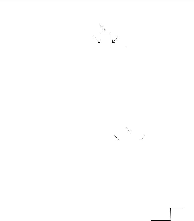
Store Count Mode 3: Store-Reset/Wait/Start
In mode 3, the rising edge of a pulse input on the Z Gate/Reset terminal stops counting, reads, and stores the current counter value in the Stored/Accumulated Count word, and resets the counter to zero. The counter does not count while the input pulse on the Z Gate/Reset terminal is high. Counting resumes from zero on the falling edge of the pulse at the Gate/Reset terminal. The stored count information remains until it is overwritten with new data.
Store-Reset/Wait/Start
Counter has stopped Counting |
|
|||
Stop Count, Store, |
Start Counting |
|||
and Reset to zero |
|
|
from zero |
|
|
||||
|
|
|
|
|
Store Count Mode 4: Store-Reset/Start
In mode 4, the rising edge of a pulse input on the Z Gate/Reset terminal stores the current counter value in the Stored/Accumulated Count word and reset the counter to zero. The counter continues counting while the Z Gate/Reset terminal is high. The stored count information remains until it is overwritten with new data.
Publication 1734-UM003B-EN-P - August 2005
1-12 About the Modules
Store-Reset/Start
|
|
Start Counting |
|
Store Count, |
|
|
|
and Reset to zero |
|
Continue Counting |
|
|
|||
|
|
|
|
Output Control
To connect an output to a compare window, you could program the module accordingly:
•Tie Output 0 to Window 0
•Program Window 0 ON Value to 2000
•Program Window 0 OFF Value to 5000
ON-OFF Operation of Output 0
Output remains energized for 3000 additional counts
Output turns ON at count value of 2000 |
|
Output turns OFF at count value of 5000 |
||
|
|
|
|
|
If the OFF value is greater than the ON value, the output turns ON at 2000 and OFF at 5000. If the ON value is greater than the OFF value, the output turns OFF at 2000 and ON at 5000.
Effect of ON-OFF Value on Output Operation |
|
|
|
||||
|
Output remains Energized |
|
Output remains Deenergized |
||||
|
for 3000 additional counts |
|
for 3000 additional counts |
||||
|
|
|
|
|
|
|
|
Output turns ON |
|
Output turns OFF |
Output turns OFF |
Output turns ON |
|||
at count of 2000 |
|
at count of 5000 |
at count of 2000 |
at count of 5000 |
|||
|
|
|
|
|
|
|
|
|
TurnOff Value > Turn On Value |
|
TurnOn Value > Turn Off Value |
||||
Publication 1734-UM003B-EN-P - August 2005

Chapter 2
Install the Module
What This Chapter Contains Read this chapter for information about how to install the modules.
The 1734-VHSC module is a two-module set. Module 1 houses the 1734-VHSC functionality while module 2 provides screw terminals necessary to access chassis ground (Chas Gnd) and common (C).
Module 2 also connects terminal 4 to 5 and terminal 6 to 7 for ease of wiring power to the input device. Module 2 is not necessary for VHSC functionality but eases customer wiring. Module 2 does not use a node address, and it doesn’t consume power from the POINTBus. To reduce loop area, place module 2 adjacent (either side) to module 1.
For Information About How To |
See Page |
|
|
Before You Begin |
2-1 |
|
|
Install the Mounting Base Assembly |
2-1 |
|
|
Install the Module |
2-4 |
|
|
Install the Removable Terminal Block |
2-6 |
|
|
Remove a Mounting Base |
2-6 |
|
|
Wire the Modules |
2-7 |
|
|
Before You Begin
ATTENTION
Preventing Electrostatic Discharge
This equipment is sensitive to electrostatic discharge, which can cause internal damage and affect normal operation. Follow these guidelines when you handle this equipment:
•Touch a grounded object to discharge potential static.
•Wear an approved grounding wriststrap.
•Do not touch connectors or pins on component boards.
•Do not touch circuit components inside the equipment.
•If available, use a static-safe workstation.
•When not in use, store the equipment in appropriate static-safe packaging.
Publication 1734-UM003B-EN-P - August 2005
Loading...