


 Loading...
1336 PLUS II
Adjustable Frequency AC Drive
with
0.37-448 kW (0.5 - 600 HP) Firmware 1.xxx - 6.xxx
User Manual
Important User Information Solid state equipment has operational characteristics differing from those of electromechanical equipment. “Safety Guidelines for the Application, Installation and Maintenance of Solid State Controls” (Publication SGI-1.1 available from your local Rockwell Automation Sales Office or online at www.rockwellautomation.com/literature) describes some important differences between solid state equipment and hard-wired electromechanical devices. Because of this difference, and also because of the wide variety of uses for solid state equipment, all persons responsible for applying this equipment must satisfy themselves that each intended application of this equipment is acceptable.
In no event will Rockwell Automation, Inc. be responsible or liable for indirect or consequential damages resulting from the use or application of this equipment.
The examples and diagrams in this manual are included solely for illustrative purposes. Because of the many variables and requirements associated with any particular installation, Rockwell Automation, Inc. cannot assume responsibility or liability for actual use based on the examples and diagrams.
No patent liability is assumed by Rockwell Automation, Inc. with respect to use of information, circuits, equipment, or software described in this manual.
Reproduction of the contents of this manual, in whole or in part, without written permission of Rockwell Automation, Inc. is prohibited.
Throughout this manual we use notes to make you aware of safety considerations.
ATTENTION: Identifies information about practices or
!circumstances that can lead to personal injury or death, property
damage, or economic loss.
Attentions help you:
•identify a hazard
•avoid the hazard
•recognize the consequences
Important: Identifies information that is especially important for successful application and understanding of the product.
Shock Hazard labels may be located on or inside the drive to alert people that dangerous voltage may be present.
StepLogic and SCANport are trademarks of Rockwell Automation, Inc.
Trademarks not belonging to Rockwell Automation are property of their respective companies.

Summary of Changes
New/Updated Information
The information below summarizes the changes to the 1336 PLUS II User Manual since the last release.
Description of Change |
Page(s) |
TB1 info updated - D Frame |
2–15, B–18 |
Updated Parameters: |
|
[Load Loss Level] |
6–26 |
[Phase Loss Level] |
6–35 |
[Heatsink Temp] |
6–39 |
[Drive Type] |
6–42 |
New Parameters: |
|
[Motor OL Ret] |
6–35 |
Parameter Cross References |
A–8 |
updated |
|
Parameter Record updated |
A–17 |

soc–2 Summary of Changes
Notes

|
Table of Contents |
|
|
Chapter 1 |
|
Information and Precautions |
Manual Objectives . . . . . . . . . . . . . . . . . . . . . . . . . . . . . . . . . . . . . . . . . |
. 1–1 |
|
Software Compatibility . . . . . . . . . . . . . . . . . . . . . . . . . . . . . . . . . . . . . . |
. 1–1 |
|
General Precautions . . . . . . . . . . . . . . . . . . . . . . . . . . . . . . . . . . . . . . . . . |
1–2 |
|
Conventions Used in this Manual . . . . . . . . . . . . . . . . . . . . . . . . . . . . . . . |
1–2 |
|
Catalog Number Explanation . . . . . . . . . . . . . . . . . . . . . . . . . . . . . . . . . . |
1–2 |
|
Nameplate Location . . . . . . . . . . . . . . . . . . . . . . . . . . . . . . . . . . . . . . . . . |
1–4 |
|
Chapter 2 |
|
Installation/Wiring |
Mounting . . . . . . . . . . . . . . . . . . . . . . . . . . . . . . . . . . . . . . . . . . . . . . . . . . |
2–1 |
|
Installation Guidelines. . . . . . . . . . . . . . . . . . . . . . . . . . . . . . . . . . . . . . . . |
2–2 |
|
AC Supply Source. . . . . . . . . . . . . . . . . . . . . . . . . . . . . . . . . . . . . . . . . . . |
2–3 |
|
Input Power Conditioning . . . . . . . . . . . . . . . . . . . . . . . . . . . . . . . . . . . . . |
2–4 |
|
Input Fuses and Circuit Breakers . . . . . . . . . . . . . . . . . . . . . . . . . . . . . . . |
2–5 |
|
Input Devices . . . . . . . . . . . . . . . . . . . . . . . . . . . . . . . . . . . . . . . . . . . . . . |
2–9 |
|
Electrical Interference - EMI/RFI. . . . . . . . . . . . . . . . . . . . . . . . . . . . . . . . |
2–9 |
|
RFI Filtering . . . . . . . . . . . . . . . . . . . . . . . . . . . . . . . . . . . . . . . . . . . . . . |
2–10 |
|
CE Conformity. . . . . . . . . . . . . . . . . . . . . . . . . . . . . . . . . . . . . . . . . . . . . |
2–10 |
|
Grounding . . . . . . . . . . . . . . . . . . . . . . . . . . . . . . . . . . . . . . . . . . . . . . . . |
2–11 |
|
Power Cabling. . . . . . . . . . . . . . . . . . . . . . . . . . . . . . . . . . . . . . . . . . . . . |
2–14 |
|
Control and Signal Wiring . . . . . . . . . . . . . . . . . . . . . . . . . . . . . . . . . . . . |
2–24 |
|
Digital Inputs . . . . . . . . . . . . . . . . . . . . . . . . . . . . . . . . . . . . . . . . . . . . . . |
2–25 |
|
Encoder Inputs . . . . . . . . . . . . . . . . . . . . . . . . . . . . . . . . . . . . . . . . . . . . |
2–30 |
|
Pulse Input/Output Option. . . . . . . . . . . . . . . . . . . . . . . . . . . . . . . . . . . . |
2–31 |
|
Digital Outputs . . . . . . . . . . . . . . . . . . . . . . . . . . . . . . . . . . . . . . . . . . . . |
2–31 |
|
Analog I/O. . . . . . . . . . . . . . . . . . . . . . . . . . . . . . . . . . . . . . . . . . . . . . . . |
2–32 |
|
Standard Analog I/O Setup . . . . . . . . . . . . . . . . . . . . . . . . . . . . . . . . . . . |
2–33 |
|
Optional Analog I/O Configurations . . . . . . . . . . . . . . . . . . . . . . . . . . . . |
2–34 |
|
Output Devices . . . . . . . . . . . . . . . . . . . . . . . . . . . . . . . . . . . . . . . . . . . . |
2–37 |
|
Cable Termination . . . . . . . . . . . . . . . . . . . . . . . . . . . . . . . . . . . . . . . . . . |
2–37 |
|
Selecting/Verifying Fan Voltage . . . . . . . . . . . . . . . . . . . . . . . . . . . . . . . |
2–38 |
|
Auxiliary Inputs - TB4, TB6 . . . . . . . . . . . . . . . . . . . . . . . . . . . . . . . . . . . |
2–39 |
|
Auxiliary Output - TB9. . . . . . . . . . . . . . . . . . . . . . . . . . . . . . . . . . . . . . . |
2–40 |
|
Control Interface Board Installation and Removal. . . . . . . . . . . . . . . . . . |
2–40 |
|
Adapter Definitions . . . . . . . . . . . . . . . . . . . . . . . . . . . . . . . . . . . . . . . . . |
2–41 |
|
Chapter 3 |
|
Human Interface Module |
HIM Description . . . . . . . . . . . . . . . . . . . . . . . . . . . . . . . . . . . . . . . . . . . . |
3–1 |
|
HIM Operation. . . . . . . . . . . . . . . . . . . . . . . . . . . . . . . . . . . . . . . . . . . . . . |
3–4 |
|
Handheld HIM Operation . . . . . . . . . . . . . . . . . . . . . . . . . . . . . . . . . . . . |
3–13 |
Chapter 4
Flash Memory |
What is Flash Memory? . . . . . . . . . . . . . . . . . . . . . . . . . . . . . . . . . . . . . . |
4–1 |
|
Firmware Download Requirements. . . . . . . . . . . . . . . . . . . . . . . . . . . . . . |
4–1 |

toc–ii Table of Contents
Chapter 5
Start-Up |
Start-Up Requirements . . . . . . . . . . . . . . . . . . . . . . . . . . . . . . . . . . . . . . |
5–1 |
|
Initial Operation . . . . . . . . . . . . . . . . . . . . . . . . . . . . . . . . . . . . . . . . . . . . |
5–2 |
|
Assisted Start-Up . . . . . . . . . . . . . . . . . . . . . . . . . . . . . . . . . . . . . . . . . . . |
5–2 |
|
Advanced Start-Up. . . . . . . . . . . . . . . . . . . . . . . . . . . . . . . . . . . . . . . . . . |
5–5 |
|
Chapter 6 |
|
Programming |
Function Index . . . . . . . . . . . . . . . . . . . . . . . . . . . . . . . . . . . . . . . . . . . . . |
6–1 |
|
Programming Flow Chart . . . . . . . . . . . . . . . . . . . . . . . . . . . . . . . . . . . . . |
6–1 |
|
Chapter Conventions . . . . . . . . . . . . . . . . . . . . . . . . . . . . . . . . . . . . . . . . |
6–4 |
|
Chapter 7 |
|
Troubleshooting |
Fault Descriptions . . . . . . . . . . . . . . . . . . . . . . . . . . . . . . . . . . . . . . . . . . |
7–1 |
|
Alarms . . . . . . . . . . . . . . . . . . . . . . . . . . . . . . . . . . . . . . . . . . . . . . . . . . . |
7–9 |
|
Appendix A |
|
Specifications and |
Specifications. . . . . . . . . . . . . . . . . . . . . . . . . . . . . . . . . . . . . . . . . . . . . . |
A–1 |
Supplemental Information |
User Supplied Enclosures . . . . . . . . . . . . . . . . . . . . . . . . . . . . . . . . . . . . |
A–4 |
|
Derating Guidelines . . . . . . . . . . . . . . . . . . . . . . . . . . . . . . . . . . . . . . . . . |
A–5 |
|
Parameter Cross Reference - By Number . . . . . . . . . . . . . . . . . . . . . . . . |
A–8 |
|
Parameter Cross Reference - By Name. . . . . . . . . . . . . . . . . . . . . . . . . . |
A–9 |
|
HIM Character Map . . . . . . . . . . . . . . . . . . . . . . . . . . . . . . . . . . . . . . . . |
A–10 |
|
Communications Data Information Format . . . . . . . . . . . . . . . . . . . . . . |
A–11 |
|
Typical Programmable Controller Communications Configurations . . . . |
A–12 |
|
Typical Serial Communications Configurations . . . . . . . . . . . . . . . . . . . |
A–13 |
|
Encoder Interface Wiring . . . . . . . . . . . . . . . . . . . . . . . . . . . . . . . . . . . . |
A–14 |
|
Read/Write Parameter Record. . . . . . . . . . . . . . . . . . . . . . . . . . . . . . . . |
A–17 |
|
Appendix B |
|
Dimensions |
|
|
|
Appendix C |
|
CE Conformity |
Requirements for Conforming Installation . . . . . . . . . . . . . . . . . . . . . . . . |
C–2 |
|
Filter . . . . . . . . . . . . . . . . . . . . . . . . . . . . . . . . . . . . . . . . . . . . . . . . . . . . . |
C–2 |
|
Electrical Configuration . . . . . . . . . . . . . . . . . . . . . . . . . . . . . . . . . . . . . . |
C–3 |
|
Grounding . . . . . . . . . . . . . . . . . . . . . . . . . . . . . . . . . . . . . . . . . . . . . . . . |
C–4 |
|
Mechanical Configuration. . . . . . . . . . . . . . . . . . . . . . . . . . . . . . . . . . . . . |
C–4 |

|
|
|
|
Chapter 1 |
|
|
Information and Precautions |
||||
|
Chapter 1 provides information on the general intent of this man- |
||||
|
ual, gives an overall description of the 1336 PLUS II Adjustable |
||||
|
Frequency AC Drive and provides a listing of key drive features. |
||||
Manual Objectives |
This publication provides planning, installation, wiring and diag- |
||||
|
nostic information for the 1336 PLUS II Drive. To assure success- |
||||
|
ful installation and operation, the material presented must be |
||||
|
thoroughly read and understood before proceeding. Particular |
||||
|
attention must be directed to the Attention and Important state- |
||||
|
ments contained within. |
|
|
|
|
|
For J Frame information, refer to publication 1336F-IN014. |
||||
Software Compatibility |
|
|
|
|
|
|
Three-Phase Drive Rating 1 |
|
Compatible with |
Frame |
|
|
200-240V |
380-480V |
500-600V |
Version . . . |
Reference |
|
|
|
|
|
|
|
0.37-0.75 kW |
0.37-1.2 kW |
– |
1.0 & Up |
A1 |
|
0.5-1 HP |
0.5-1.5 HP |
|
|
|
|
1.2-1.5 kW |
1.5-2.2 kW |
– |
1.0 & Up |
A2 |
|
1.5-2 HP |
2-3 HP |
|
|
|
|
2.2-3.7 kW |
3.7 kW |
– |
1.0 & Up |
A3 |
|
3-5 HP |
5 HP |
|
|
|
|
5.5 kW |
5.5-15 kW |
0.75-15 kW |
1.0 & Up |
A4 |
|
7.5 HP |
7.5-20 HP |
1-20 HP |
|
|
|
5.5-11 kW |
11-22 kW |
– |
1.0 & Up |
B1/B2 |
|
7.5-15 HP |
15-30 HP |
|
|
|
|
15-22 kW |
30-45 kW |
18.5-45 kW |
1.0 & Up |
C |
|
20-30 HP |
40-60 HP |
25-60 HP |
|
|
|
30-45 kW |
45-112 kW |
56-93 kW |
1.0 & Up |
D |
|
40-60 HP |
60-150 HP |
75-125 HP |
|
|
|
56-93 kW |
112-187 kW |
112-224 kW |
1.0 & Up |
E |
|
75-125 HP |
150-250 HP |
150-300 HP |
|
|
|
– |
187-336 kW |
261-298 kW |
1.0 & Up |
F |
|
|
250-450 HP |
350-400 HP |
|
|
|
– |
187-448 kW |
224-448 kW |
1.0 & Up |
G |
|
|
250-600 HP |
300-600 HP |
|
|
1 kW and HP are constant torque.
1–2 |
Information and Precautions |
General Precautions
!
ATTENTION: This drive contains ESD (Electrostatic Discharge) sensitive parts and assemblies. Static control precautions are required when installing, testing, servicing or repairing this assembly. Component damage may result if ESD control procedures are not followed. If you are not familiar with static control procedures, reference A-B publication 8000-4.5.2, “Guarding Against Electrostatic Damage” or any other applicable ESD protection handbook.
!
!
!
ATTENTION: An incorrectly applied or installed drive can result in component damage or a reduction in product life. Wiring or application errors, such as, undersizing the motor, incorrect or inadequate AC supply, or excessive ambient temperatures may result in malfunction of the system.
ATTENTION: Only personnel familiar with the 1336 PLUS II Adjustable Frequency AC Drive and associated machinery should plan or implement the installation, startup and subsequent maintenance of the system. Failure to comply may result in personal injury and/or equipment damage.
ATTENTION: To avoid a hazard of electric shock, verify that the voltage on the bus capacitors has discharged before performing any work on the drive. Measure the DC bus voltage at the + & - terminals of TB1. The voltage must be 0.0V DC.
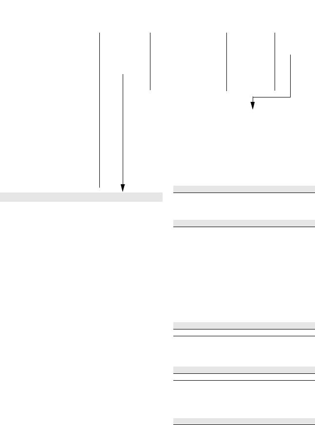
Conventions Used in this Manual
Catalog Number Explanation
To help differentiate parameter names and display text from other text the following conventions will be used:
•Parameter Names will appear in [brackets]
•Display Text will appear in “quotes”
The diagram on the following page describes the 1336 PLUS II catalog numbering scheme.
Information and Precautions |
1–3 |
1336F |
– BR |
|
|
First Position |
|
Second Position |
|
|
|||
Bulletin Number |
|
Voltage |
|
|
|
Letter |
Voltages |
|
|
AQ |
200-240V AC or |
|
|
|
310V DC |
|
|
BR |
380-480VAC or |
|
|
|
513-620V DC |
|
|
CW |
500-600V AC or |
|
|
|
775V DC |
|
|
A |
200-240V AC |
|
|
B |
380-480V AC |
|
|
BP/BPR 380-480V AC |
|
|
|
|
(F Frame) |
|
|
BX |
Special Rating |
|
|
C |
500-600V AC |
|
|
CP/CPR 500-600V AC |
|
|
|
|
(F Frame) |
|
|
Q |
310V DC |
|
|
R |
513-620V DC |
|
|
RX |
Special Rating |
|
|
W |
775V DC |
|
|
|
|
F30 – AA
Third Position
Nominal HP Rating
Refer to table below for ratings and possible voltage combinations.
Fourth Position
Enclosure Type
Code |
Type |
|
|
AA |
IP 20 (NEMA 1) |
|
|
AE |
IP 20 |
(NEMA 1)/EMC |
|
AF |
IP 65 |
(NEMA 4) |
|
AJ |
IP 54 |
(NEMA 12) |
|
AN |
IP 00 |
(Open) |
|
– EN |
– |
MODS |
Fifth Position |
|
Sixth Position |
Language Group |
Options |
|
Code Language
EN |
English |
FR |
French |
DE |
German |
IT |
Italian |
ES |
Spanish |
JP |
Japanese |
Code |
Description |
Human Interface Module, Snap-In, IP20 (NEMA Type 1) |
|
HASB |
Snap-In Cradle/Blank Plate |
HASP |
Programmer Only |
HCSP |
Programmer Only & Upload/Download Capability |
HAS1 |
Programmer/Controller w/Analog Pot |
HCS1 |
Programmer/Controller w/Analog Pot & Upload/Download Capability |
HAS2 |
Programmer/Controller w/Digital Pot |
HCS2 |
Programmer/Controller w/Digital Pot & Upload/Download Capability |
Human Interface Module, IP65/54 (NEMA Type 4/12) |
|
HJP |
Programmer Only |
HJ2 |
Programmer/Controller w/Digital Pot |
Communication Options –- B Frame & Up (Adapter 6)
Voltage and Nominal HP Rating Combinations
|
|
|
|
|
|
|
|
|
BP/ |
|
|
CP/ |
|
|
|
|
Code |
Rating |
AQ |
BR |
CW |
A |
B |
BPR |
BX |
C |
CPR |
Q |
R |
RX |
W |
||
F05 |
0.37 (0.5) |
● |
● |
|
|
|
|
|
|
|
|
|
|
|
||
F07 |
0.56 (0.75) |
● |
● |
|
|
|
|
|
|
|
|
|
|
|
||
F10 |
0.75 (1) |
● |
● |
● |
|
|
|
|
|
|
|
|
|
|
||
F15 |
1.2 |
(1.5) |
● |
● |
|
|
|
|
|
|
|
|
|
|
|
|
F20 |
1.5 |
(2) |
● |
● |
● |
|
|
|
|
|
|
|
|
|
|
|
F30 |
2.2 |
(3) |
● |
● |
● |
|
|
|
|
|
|
|
|
|
|
|
F50 |
3.7 |
(5) |
● |
● |
● |
|
|
|
|
|
|
|
|
|
|
|
F75 |
5.5 |
(7.5) |
● |
● |
● |
|
|
|
|
|
|
|
|
|
|
|
F100 |
7.5 |
(10) |
|
● |
● |
|
|
|
|
|
|
|
|
|
|
|
F150 |
11 |
(15) |
|
● |
● |
|
|
|
|
|
|
|
|
|
|
|
F200 |
15 |
(20) |
|
● |
● |
|
|
|
|
|
|
|
|
|
|
|
007 |
5.5 |
(7.5) |
|
|
|
● |
|
|
|
|
|
● |
|
|
|
|
010 |
7.5 |
(10) |
|
|
|
● |
|
|
|
|
|
● |
|
|
|
|
015 |
11 |
(15) |
|
|
|
● |
● |
|
|
|
|
● |
● |
|
|
|
020 |
15 |
(20) |
|
|
|
● |
● |
|
|
|
|
● |
● |
|
|
|
025 |
18.5 (25) |
|
|
|
● |
● |
|
|
● |
|
● |
● |
|
● |
||
030 |
22 |
(30) |
|
|
|
● |
● |
|
|
● |
|
● |
● |
|
● |
|
040 |
30 |
(40) |
|
|
|
● |
● |
|
● |
● |
|
● |
● |
● |
● |
|
050 |
37 |
(50) |
|
|
|
● |
● |
|
|
● |
|
● |
● |
|
● |
|
060 |
45 |
(60) |
|
|
|
● |
● |
|
● |
● |
|
● |
● |
● |
● |
|
075 |
56 |
(75) |
|
|
|
● |
● |
|
|
● |
|
● |
● |
|
● |
|
100 |
75 |
(100) |
|
|
|
● |
● |
|
|
● |
|
● |
● |
|
● |
|
125 |
93 |
(125) |
|
|
|
● |
● |
|
|
● |
|
● |
● |
|
● |
|
150 |
112 |
(150) |
|
|
|
|
● |
|
● |
● |
|
|
● |
● |
● |
|
200 |
149 |
(200) |
|
|
|
|
● |
|
|
● |
|
|
● |
|
● |
|
250 |
187 |
(250) |
|
|
|
|
● |
● |
● |
● |
|
|
● |
● |
● |
|
300 |
224 |
(300) |
|
|
|
|
● |
● |
|
● |
|
|
● |
|
● |
|
350 |
261 |
(350) |
|
|
|
|
● |
● |
|
● |
● |
|
● |
|
● |
|
400 |
298 |
(400) |
|
|
|
|
● |
● |
|
● |
● |
|
● |
|
● |
|
450 |
336 |
(450) |
|
|
|
|
● |
● |
|
● |
|
|
● |
|
● |
|
500 |
373 |
(500) |
|
|
|
|
● |
|
|
● |
|
|
● |
|
● |
|
600 |
448 |
(600) |
|
|
|
|
● |
|
|
● |
|
|
● |
|
● |
|
Language must be specified to ensure shipment of appropriate User Manual.
G Frame Standard Drives in enclosed construction are supplied through the Configured Drives Program and will have an “A” suffix after the HP rating.
D through G Frame drives in IP 65 (NEMA Type 4) and IP 54 (NEMA Type 12) configurations are supplied through the Configured Drives Program.
“xPR” has a “roll-in” type chassis. Not available with v5.001 & later.
GM1 |
Single Point Remote I/O B Frame |
GM2 |
RS-232/422/485, DF1 & DH485 B Frame |
GM5 |
DeviceNet™ |
GM6 |
Enhanced DeviceNet™ |
Communication Options –- All Frames (Adapter 1)
GMS1 |
GM1 with Snap-In Cradle |
GMS2 |
GM2 with Snap-In Cradle |
GMS5 |
GM5 with Snap-In Cradle |
GMS6 |
GM6 with Snap-In Cradle |
Control Interface Options |
|
L4 |
TTL Contact |
L4E |
TTL Contact & Encoder Feedback |
L7E |
TTL Contact & Encoder Fdbck. for use with Encoder Loss Detection |
L5 |
24V AC/DC |
L5E |
24V AC/DC & Encoder Feedback |
L8E |
24V AC/DC & Encoder Feedback for use with Encoder Loss Detection |
L6 |
115V AC |
L6E |
115V AC & Encoder Feedback |
L9E |
115V AC & Encoder Feedback for use with Encoder Loss Detection |
Analog Interface Options – Slot A
• Choose No More than One – Configurable Inputs/Outputs are 10V or 20mA
LA2 |
Two Isolated Configurable Inputs |
LA6 |
One Isolated Bi-polar Input (±10V or ±20mA) and One Isolated |
|
Thermistor Input |
LA7 |
One Isolated Bi-polar Input (±10V or ±20mA) and One Isolated |
|
Configurable Input |
Analog Interface Options – Slot B
• Choose No More than One – Configurable Inputs/Outputs are 10V or 20mA
LA1 |
Single-ended, Non-isolated Configurable (including Pot) Input & 2 |
|
Single-ended, Non-isolated Outputs (1 - Configurable, 1 - 20mA) |
LA3 |
Two Isolated Configurable Outputs |
LA4 |
One Isolated Configurable Input & Output |
LA5 |
Isolated Pulse Input, Non-isolated Pulse Output & Single-ended, |
|
Non-isolated Configurable Output |
Common Mode Choke –- F & G Frame (must be specified for F Frame)
CM |
Internal Common Mode Choke (factory installed) |
NCM |
No Common Mode Choke |
1–4 |
Information and Precautions |
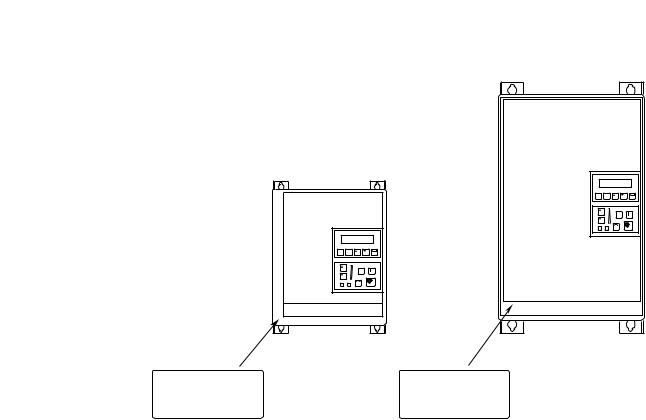
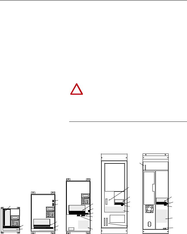
Nameplate Location
Figure 1.1
1336 PLUS II Nameplate Location
1 Refer to page 1-1 for frame reference classifications.
ESC |
SEL |
|
JOG |
Frames1 A1, A2, A3, A4 |
Frames1 B - G |
Nameplate Located on |
Nameplate Located on |
Bottom Portion of |
Mounting Plate of |
Chassis Behind Cover |
Main Control Board |
Chapter 2
Installation/Wiring
Chapter 2 provides the information you need to properly mount and wire the 1336 PLUS II Drive. Since most start-up difficulties are the result of incorrect wiring, every precaution must be taken to assure that the wiring is done as instructed. All items must be read and understood before the actual installation begins.
ATTENTION: The following information is merely a
!guide for proper installation. The Allen-Bradley Company cannot assume responsibility for the compliance or the noncompliance to any code, national, local or otherwise for the proper installation of this drive or associated equipment. A hazard of personal injury and/or equipment damage exists if codes are ignored during installation.
Mounting
Minimum Mounting Requirements for Proper Heat Dissipation
(Dimensions shown are between drives or other devices)
152.4 mm
(6.0 in.)
|
101.6 mm |
|
(4.0 in.) |
ESC |
SEL |
|
JOG |
|
UP |
152.4 mm
(6.0 in.)
152.4 mm
(6.0 in.)
ESC |
JOG |
152.4 mm
(6.0 in.)
Important:
A4 Frame drives should not be mounted on a combustible surface. However,
if the drive must be mounted on a combustible surface, 6.35 mm (0.25 in.) spacers must be provided under the mounting feet of the drive.
F Frame drives require a minimum of 152.4 mm (6.0 in.) between the drive back and mounting wall, if drives are mounted with sides touching another device or wall. A minimum of 76.2 mm (3.0 in.) is required on the sides if the back of the drive is mounted against a wall or other device.
2–2 Installation/Wiring
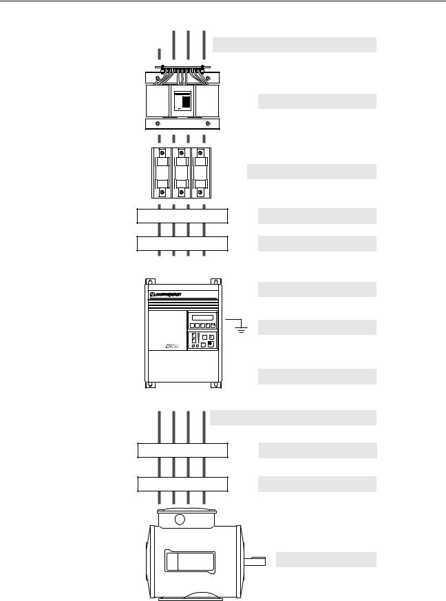
Installation Guidelines
GND
PE R S T
GND (L1) (L2) (L3)
ESC SEL
JOG
PE (T1) (T2) (T3)
GND U V W
AC Supply Source
Input Power Conditioning
Input Fusing & Circuit Breakers
Input Devices
Input Filters
Electrical Interference
Grounding
Power Cabling
Control & Signal Cabling
Output Devices
Cable Termination
Motor
Page 2–3
Page 2–4
Page 2–5
Page 2–9
Page 2–10
Page 2–9
Page 2–11
Page 2–14
Page 2–24
Page 2–37
Page 2–37
Installation/Wiring |
2–3 |
AC Supply Source |
1336 PLUS II drives are suitable for use on a circuit capable of deliv- |
|
ering up to a maximum of 200,000 rms symmetrical amperes, 600 |
|
volts. Refer to Table 2.A for actual interrupt ratings based on fuse or |
|
circuit breaker choice. |
|
|
|
ATTENTION: To guard against personal injury and/or |
!equipment damage caused by improper fusing, use only the recommended line fuses specified in Table 2.A.
Unbalanced Distribution Systems
This drive is designed to operate on three-phase supply systems whose line voltages are symmetrical. Surge suppression devices are included to protect the drive from lightning induced overvoltages between line and ground. Where the potential exists for abnormally high phase-to-ground voltages (in excess of 125% of nominal), or where the supply ground is tied to another system or equipment that could cause the ground potential to vary with operation, suitable isolation is required for the drive. Where this potential exists, an isolation transformer is strongly recommended.
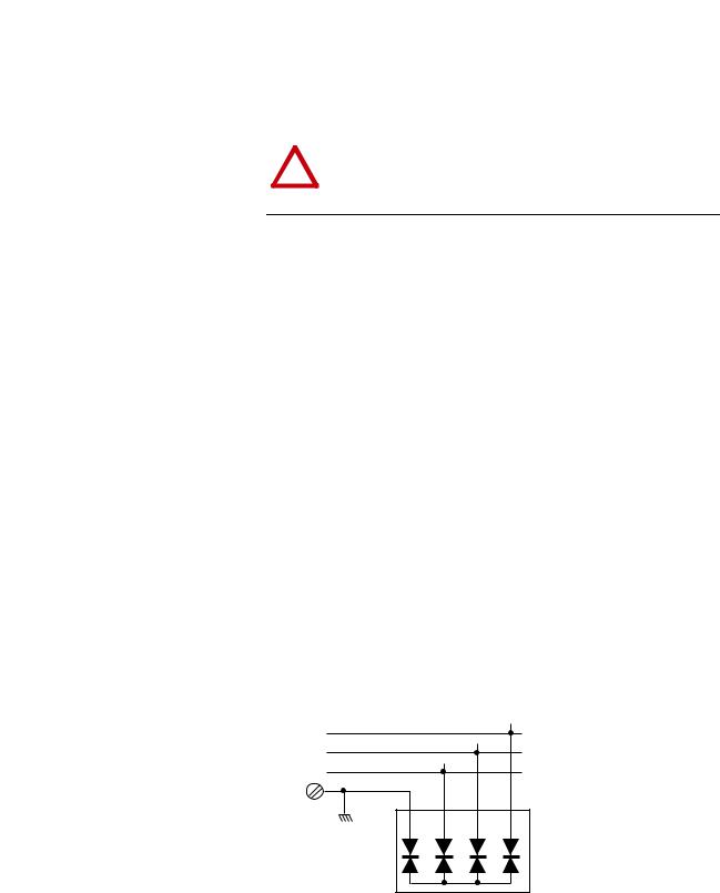
Ungrounded Distribution Systems
All 1336 PLUS II drives are equipped with an MOV (Metal Oxide Varistor) that provides voltage surge protection and phase-to-phase plus phase-to-ground protection which is designed to meet IEEE 587. The MOV circuit is designed for surge suppression only (transient line protection), not continuous operation.
With ungrounded distribution systems, the phase-to-ground MOV connection could become a continuous current path to ground. Energy ratings are listed below. Exceeding the published phase-to- phase or phase-to-ground energy ratings may cause physical damage to the MOV. Refer to page A-1.
Three-Phase |
R |
Joules (J) |
Phase-to-Phase MOV Rating |
|
S |
Joules (J) |
Includes 2 Phase-Phase MOVs |
||
AC Input |
|
|
|
|
T |
Joules (J) |
Phase-to-Ground MOV Rating |
||
|
||||
Ground |
|
Joules (J) |
Includes Phase-Phase & Phase-Ground MOVs |
|
|
|
|
1 |
2 |
3 |
4 |
Frame Reference |
A |
|
B-C |
|
D-G |
|
|
Device Rating (V AC) |
240 |
480/600 |
240/480 |
600 |
240/480 |
600 |
|
Phase-Phase Total |
160J |
320J |
280J |
320J |
280J |
300J |
|
Phase-Ground Total |
220J |
380J |
360J |
410J |
360J |
370J |
|

2–4 Installation/Wiring
Input Power Conditioning |
In general, the 1336 PLUS II is suitable for direct connection to an AC |
|
line of the correct voltage. Certain conditions can exist, however, that |
|
prompt consideration of a line reactor or isolation transformer ahead |
|
of the drive. |
|
The basic rules to aid in determining whether a line reactor or isola- |
|
tion transformer should be considered are as follows: |
1.If the AC source experiences frequent power outages or significant voltage transients, users should calculate the VAmax (see formula below). If the source transformer VA exceeds the calculated VAmax and the drive is installed close to the source, it is an indication that there may be enough energy behind these voltage transients to cause nuisance input fuse blowing, overvoltage faults or drive power structure damage. In these cases, a line reactor or isolation transformer should be considered.
Zdrive (Ω/Φ) = |
|
|
Vline-line |
√ |
|
x Input Amps |
|
3 |
VAmax = |
(Vline-line)2 |
x % Source Leakage (5-6% typical) |
|
Zdrive x 0.01 |
|
|
|
2.If the AC source does not have a neutral or one phase referenced to ground (see Unbalanced Distribution Systems on page 2–3), an isolation transformer with the neutral of the secondary grounded is highly recommended. If the line-to-ground voltages on any phase can exceed 125% of the nominal line-to-line voltage, an isolation transformer with the neutral of the secondary grounded, is highly recommended.
3.If the AC line supplying the drive has power factor correction capacitors that are switched in and out, an isolation transformer or 5% line reactor is recommended between the drive and capacitors. If the capacitors are permanently connected and not switched, the general rules above apply.

Installation/Wiring 2–5
Input Fuses and Circuit
Breakers
The 1336 PLUS II can be installed with either input fuses or an input circuit breaker. Local/national electrical codes may determine additional requirements for these installations.
The tables on the following pages provide drive ratings and recommended AC line input fuse and circuit breaker information. Both types of short circuit protection are acceptable for UL and IEC requirements. Sizes listed are the recommended sizes based on 40 degree C and the U.S. N.E.C. Other country, state or local codes may require different ratings.
ATTENTION: The 1336 PLUS II does not provide input
!power short circuit protection. Specifications for the recommended fuse or circuit breaker to provide drive input power protection against short circuits are provided.
Fusing
If fuses are chosen as the desired protection method, refer to the recommended types listed below. If available amp ratings do not match the tables provided, the closest fuse rating that exceeds the drive rating should be chosen.
•IEC – BS88 (British Standard) Parts 1 & 21, EN60269-1, Parts 1 & 2, type gG or equivalent should be used.
•UL – UL Class CC, T, RK1 or J must be used.
Circuit Breakers
The “non-fuse” listings in the following tables include both circuit breakers (inverse time or instantaneous trip) and 140M Self-Protect- ing Motor Starters. If one of these is chosen as the desired protection method, the following requirements apply.
•IEC and UL – Both types of devices are acceptable for IEC and UL installations
1.Typical designations include, but may not be limited to the following; Parts 1 & 2: AC, AD, BC, BD, CD, DD, ED, EFS, EF, FF, FG, GF, GG, GH.

2–6 Installation/Wiring
Table 2.A
240 Volt Input Protection Devices
|
Drive |
|
|
|
Dual-Element |
|
|
|
Motor |
|
|
|
|
|
Frame |
Catalog |
HP |
Input |
Output |
Time Delay |
Non-Time |
Circuit |
Circuit |
Available Catalog Numbers7 |
|
|
|||
1336F- |
Amps |
Amps |
Min.1 |
Max.2 |
Min.1 |
Max.2 |
Max.8 |
Max.8 |
|
|
||||
|
Number |
|
Rating |
Rating |
Fuse |
|
Delay Fuse |
Breaker3 |
Protector4,9 |
140M Motor Starter with Adjustable Current Range5, 6 |
||||
|
|
|
|
|
|
|
|
|
|
|
|
|
|
|
A1 |
F05 |
0.5 |
2.8 |
2.3 |
4 |
5 |
4 |
6 |
15 |
3 |
140M-C2E-B40 |
140M-D8E-B40 |
– |
– |
|
F07 |
0.75 |
3.5 |
3.0 |
4 |
6 |
4 |
9 |
15 |
7 |
140M-C2E-B40 |
140M-D8E-B40 |
– |
– |
|
F10 |
1 |
5.4 |
4.5 |
6 |
9 |
6 |
12 |
15 |
7 |
140M-C2E-B63 |
140M-D8E-B63 |
– |
– |
A2 |
F15 |
1.5 |
7.3 |
6.0 |
8 |
12.5 |
8 |
15 |
20 |
15 |
140M-C2E-C10 |
140M-D8E-C10 |
140M-F8E-C10 |
– |
|
F20 |
2 |
9.7 |
8.0 |
10 |
15 |
10 |
20 |
25 |
15 |
140M-C2E-C10 |
140M-D8E-C10 |
140M-F8E-C10 |
– |
A3 |
F30 |
3 |
14.3 |
12.0 |
15 |
20 |
15 |
25 |
35 |
15 |
140M-C2E-C16 |
140M-D8E-C16 |
140M-F8E-C16 |
– |
|
F50 |
5 |
21.3 |
18.0 |
25 |
30 |
25 |
45 |
60 |
30 |
140M-C2E-C25 |
140M-D8E-C25 |
140M-F8E-C25 |
140M-CMN-2500 |
|
F75 |
7.5 |
22.6 |
22.0 |
30 |
45 |
30 |
60 |
80 |
50 |
140M-C2E-C25 |
140M-D8E-C25 |
140M-F8E-C25 |
140M-CMN-2500 |
B |
007 |
7.5 |
28.0 |
27.0 |
40 |
45 |
40 |
60 |
80 |
50 |
– |
– |
140M-F8E-C32 |
140M-CMN-4000 |
|
010 |
10 |
35.0 |
34.0 |
50 |
60 |
50 |
80 |
100 |
50 |
– |
– |
– |
140M-CMN-4000 |
|
015 |
15 |
49.0 |
48.0 |
70 |
90 |
70 |
110 |
150 |
70 |
– |
– |
– |
140M-CMN-6300 |
C |
020 |
20 |
63.0 |
65.0 |
100 |
110 |
100 |
125 |
200 |
100 |
– |
– |
– |
140M-CMN-9000 |
|
025 |
25 |
75.0 |
77.0 |
100 |
150 |
100 |
200 |
250 |
100 |
– |
– |
– |
140M-CMN-9000 |
|
030 |
30 |
79.0 |
80.0 |
125 |
175 |
125 |
225 |
300 |
150 |
– |
– |
– |
140M-CMN-9000 |
D |
040 |
40 |
119.0 |
120.0 |
120 |
225 |
120 |
300 |
300 |
150 |
– |
– |
– |
– |
|
050 |
50 |
149.0 |
150.0 |
200 |
250 |
200 |
350 |
350 |
250 |
– |
– |
– |
– |
|
060 |
60 |
178.0 |
180.0 |
250 |
300 |
250 |
450 |
450 |
250 |
– |
– |
– |
– |
E |
075 |
75 |
238.0 |
240.0 |
300 |
400 |
300 |
500 |
500 |
250 |
– |
– |
– |
– |
|
100 |
100 |
289.0 |
291.0 |
400 |
500 |
400 |
700 |
700 |
400 |
– |
– |
– |
– |
|
125 |
125 |
322.0 |
325.0 |
450 |
700 |
450 |
800 |
800 |
600 |
– |
– |
– |
– |
1Minimum protection device size is the lowest rated device that supplies maximum protection without nuisance tripping.
2Maximum protection device size is the highest rated device that supplies drive protection.
3Circuit Breaker - inverse time breaker.
4Motor Circuit Protector - instantaneous trip circuit breaker.
5Bulletin 140M with adjustable current range should have the current trip set to the minimum range that the device will not trip.
6Manual Self-Protected (Type E) Combination Motor Controller, UL listed for 208 Wye or Delta, 240 Wye or Delta, 480Y/277 or 600Y/ 347. Not UL listed for use on 480V or 600V Delta/Delta systems.
7The AIC ratings of the Bulletin 140M Motor Protector may vary. See publication 140M-SG001B-EN-P.
8Maximum rating allowed by US NEC. Exact size must be chosen for each installtion.
9The Maximum Short Circuit Rating of a Cutler-Hammer Series HMCP is 100,000A at 240 volts, 65,000A at 480 volts and 25,000A at 575 volts.

|
|
|
|
|
|
|
|
|
|
|
|
|
|
|
Installation/Wiring |
2–7 |
||
|
|
|
|
|
|
|
|
Table 2.A (continued) |
|
|
|
|
|
|
|
|||
|
|
|
|
|
|
|
|
480 Volt Input Protection Devices |
|
|
|
|
|
|||||
|
|
|
|
|
|
|
|
|
|
|
|
|
|
|
|
|
|
|
|
|
CT Ratings |
|
VT Ratings |
|
|
|
|
|
|
Motor |
|
|
|
|
|
||
|
Drive |
|
|
|
|
|
|
Dual Element |
|
|
Circuit |
Circuit |
140M Motor Starter with Adjustable Current Range5, |
|||||
|
|
|
|
|
|
|
|
|
||||||||||
Frame |
Catalog |
|
|
|
|
|
|
Time Delay |
Non-Time |
Breaker |
Protector |
|||||||
1336F- |
HP |
Amps |
Amps |
HP |
Amps |
Amps |
Min.1 |
Max.2 |
Min.1 |
Max.2 |
3 |
4,9 |
6 |
|
|
|
|
|
Max.8 |
Max.8 |
Available Catalog Numbers - 140 . . .7 |
|
|||||||||||||||
|
Number |
|
Input |
Output |
|
Input |
Output |
Fuse |
|
Delay Fuse |
|
|
|
|
|
|
|
|
|
|
|
|
|
|
|
|
|
|
|
|
|
|
|
|
|
|
|
A1 |
F05 |
0.5 |
1.3 |
1.1 |
0.5 |
1.4 |
1.2 |
3 |
2.5 |
3 |
3 |
15 |
3 |
M-C2E-B16 |
– |
– |
– |
|
|
F07 |
0.75 |
2.0 |
1.6 |
0.75 |
2.1 |
1.7 |
3 |
3 |
3 |
6 |
15 |
3 |
M-C2E-B25 |
– |
– |
– |
|
|
F10 |
1 |
2.6 |
2.1 |
1 |
2.8 |
2.3 |
3 |
4.5 |
3 |
8 |
15 |
3 |
M-C2E-B40 |
M-D8E-B40 |
– |
– |
|
|
F15 |
1.5 |
3.3 |
2.8 |
1.5 |
3.5 |
3.0 |
4 |
6 |
4 |
12 |
15 |
7 |
M-C2E-B40 |
M-D8E-B40 |
– |
– |
|
A2 |
F20 |
2 |
4.6 |
3.8 |
2 |
4.8 |
4.0 |
5 |
6 |
5 |
12 |
15 |
7 |
M-C2E-C63 |
M-D8E-C63 |
– |
– |
|
|
F30 |
3 |
6.4 |
5.3 |
3 |
7.2 |
6.0 |
8 |
10 |
8 |
15 |
25 |
7 |
M-C2E-C10 |
M-D8E-C10 |
M-F8E-C10 |
– |
|
A3 |
F50 |
5 |
10.0 |
8.4 |
5 |
10.7 |
9.0 |
12 |
15 |
12 |
30 |
35 |
15 |
M-C2E-C16 |
M-D8E-C16 |
M-F8E-C16 |
– |
|
A4 |
F75 |
7.5 |
13.6 |
13.3 |
10 |
15.7 |
15.4 |
20 |
30 |
20 |
50 |
50 |
30 |
M-C2E-C16 |
M-D8E-C16 |
M-F8E-C16 |
– |
|
|
F100 |
10 |
16.4 |
16.1 |
15 |
22.4 |
22.0 |
30 |
40 |
30 |
80 |
80 |
30 |
M-C2E-C25 |
M-D8E-C25 |
M-F8E-C25 |
-CMN-2500 |
|
|
F150 |
15 |
24.5 |
24.0 |
20 |
24.5 |
24.0 |
35 |
60 |
35 |
100 |
100 |
50 |
M-C2E-C25 |
M-D8E-C25 |
M-F8E-C25 |
-CMN-2500 |
|
|
F200 |
20 |
28.0 |
27.0 |
20 |
28.0 |
27.0 |
35 |
60 |
35 |
100 |
100 |
50 |
– |
|
– |
M-F8E-C32 |
-CMN-4000 |
B |
015 |
15 |
25.0 |
24.2 |
20 |
28.0 |
27.0 |
35 |
60 |
35 |
100 |
100 |
50 |
– |
|
– |
M-F8E-C32 |
-CMN-4000 |
|
020 |
20 |
32.0 |
31.0 |
25 |
35.0 |
34.0 |
45 |
70 |
45 |
125 |
125 |
50 |
– |
|
– |
M-F8E-C45 |
-CMN-4000 |
|
025 |
25 |
40.0 |
39.0 |
30 |
43.0 |
42.0 |
60 |
90 |
60 |
150 |
150 |
70 |
– |
|
– |
M-F8E-C45 |
-CMN-6300 |
|
030 |
30 |
46.0 |
45.0 |
30 |
49.0 |
48.0 |
70 |
90 |
70 |
150 |
150 |
70 |
– |
|
– |
– |
-CMN-6300 |
C |
X040 |
40 |
61.0 |
59.0 |
40 |
61.0 |
59.0 |
80 |
110 |
80 |
200 |
200 |
70 |
– |
|
– |
– |
-CMN-6300 |
|
040 |
40 |
58.0 |
60.0 |
50 |
63.0 |
65.0 |
80 |
125 |
80 |
250 |
250 |
100 |
– |
|
– |
– |
-CMN-6300 |
|
050 |
50 |
73.0 |
75.0 |
60 |
75.0 |
77.0 |
100 |
150 |
100 |
300 |
300 |
100 |
– |
|
– |
– |
-CMN-9000 |
|
X060 |
60 |
75.0 |
77.0 |
60 |
75.0 |
77.0 |
100 |
150 |
100 |
300 |
300 |
100 |
– |
|
– |
– |
-CMN-9000 |
D |
060 |
60 |
82.0 |
85.0 |
75 |
93.0 |
96.0 |
125 |
200 |
125 |
350 |
350 |
150 |
– |
|
– |
– |
– |
|
075 |
75 |
105.0 |
106.0 |
100 |
119.0 |
120.0 |
150 |
250 |
150 |
450 |
350 |
250 |
– |
|
– |
– |
– |
|
100 |
100 |
137.0 |
138.0 |
125 |
149.0 |
150.0 |
200 |
350 |
200 |
600 |
450 |
250 |
– |
|
– |
– |
– |
|
125 |
125 |
172.0 |
173.0 |
150 |
178.0 |
180.0 |
250 |
400 |
250 |
600 |
500 |
250 |
– |
|
– |
– |
– |
|
X150 |
150 |
178.0 |
180.0 |
150 |
178.0 |
180.0 |
250 |
400 |
250 |
600 |
500 |
250 |
– |
|
– |
– |
– |
E |
150 |
150 |
197.0 |
199.0 |
200 |
238.0 |
240.0 |
300 |
500 |
300 |
700 |
700 |
400 |
– |
|
– |
– |
– |
|
200 |
200 |
261.0 |
263.0 |
250 |
290.0 |
292.0 |
400 |
600 |
400 |
800 |
800 |
400 |
– |
|
– |
– |
– |
|
250 |
250 |
322.0 |
325.0 |
250 |
322.0 |
325.0 |
450 |
600 |
450 |
800 |
800 |
400 |
– |
|
– |
– |
– |
F |
P250 |
250 |
322.0 |
325.0 |
300 |
357.0 |
360.0 |
450 |
– |
|
|
|
|
|
|
|
|
|
|
P300 |
300 |
357.0 |
360.0 |
350 |
421.0 |
425.0 |
500 |
– |
|
|
|
Semiconductor fuse supplied with drive. |
|
||||
|
P350 |
350 |
421.0 |
425.0 |
400 |
471.0 |
475.0 |
600 |
– |
|
|
|
|
|||||
|
Refer to the 1336 Spare Parts list (publication 1336-6.5) for replacement information. |
|||||||||||||||||
|
P400 |
400 |
471.0 |
475.0 |
450 |
527.0 |
532.0 |
600 |
– |
|||||||||
|
|
|
|
|
|
|
|
|
|
|||||||||
|
P450 |
450 |
527.0 |
532.0 |
|
|
|
700 |
– |
|
|
|
|
|
|
|
|
|
G |
X250 |
250 |
322.0 |
325.0 |
300 |
357.0 |
360.0 |
450 |
– |
|
|
|
|
|
|
|
|
|
|
300 |
300 |
357.0 |
360.0 |
350 |
421.0 |
425.0 |
450 |
– |
|
|
|
|
|
|
|
|
|
|
350 |
350 |
421.0 |
425.0 |
400 |
471.0 |
475.0 |
500 |
– |
|
|
|
Bussmann Type FWP, SPP, or 170M Series |
|
||||
|
400 |
400 |
471.0 |
475.0 |
450 |
521.0 |
525.0 |
600/630 |
– |
|
|
|
|
|||||
|
|
|
Ferraz Shawmut Type A-70Q, A-70QS or A070URD Series |
|
||||||||||||||
|
450 |
450 |
521.0 |
525.0 |
500 |
585.0 |
590.0 |
800 |
– |
|
|
|
||||||
|
|
|
|
|
|
|
|
|
|
|||||||||
|
500 |
500 |
585.0 |
590.0 |
600 |
664.0 |
670.0 |
800 |
– |
|
|
|
|
|
|
|
|
|
|
600 |
600 |
664.0 |
670.0 |
600 |
664.0 |
670.0 |
900 |
- |
|
|
|
|
|
|
|
|
|
1Minimum protection device size is the lowest rated device that supplies maximum protection without nuisance tripping.
2Maximum protection device size is the highest rated device that supplies drive protection.
3Circuit Breaker - inverse time breaker.
4Motor Circuit Protector - instantaneous trip circuit breaker.
5Bulletin 140M with adjustable current range should have the current trip set to the minimum range that the device will not trip.
6Manual Self-Protected (Type E) Combination Motor Controller, UL listed for 208 Wye or Delta, 240 Wye or Delta, 480Y/277 or 600Y/ 347. Not UL listed for use on 480V or 600V Delta/Delta systems.
7The AIC ratings of the Bulletin 140M Motor Protector may vary. See publication 140M-SG001B-EN-P.
8Maximum rating allowed by US NEC. Exact size must be chosen for each installtion.
9The Maximum Short Circuit Rating of a Cutler-Hammer Series HMCP is 100,000A at 240 volts, 65,000A at 480 volts and 25,000A at 575 volts.

2–8 |
|
Installation/Wiring |
|
|
|
|
|
|
|
|
|
|
|
||||
|
|
|
|
|
|
|
|
|
Table 2.A (continued) |
|
|
|
|
|
|||
|
|
|
|
|
|
|
|
|
575 Volt Input Protection Devices |
|
|
|
|||||
|
|
|
|
|
|
|
|
|
|
|
|
|
|
|
|
|
|
|
|
CT Ratings |
|
|
|
|
|
|
|
Motor |
|
|
|
|
|
||
|
Drive |
|
|
|
|
|
|
|
|
|
Circuit |
Circuit |
|
|
|
|
|
|
|
|
|
|
|
|
|
|
|
|
|
|
|
|
|||
Frame |
Catalog |
HP |
|
Amps |
Amps |
Dual Element |
Non-Time |
Breaker |
Protector |
Available Catalog Numbers7 |
|
|
|||||
1336F- |
|
Min. |
1 |
Max.2 |
Min.1 |
Max.2 |
Max.8 |
Max.8 |
|
|
|
||||||
|
Number |
|
|
Input |
Output |
Time Delay Fuse |
Delay Fuse |
3 |
4,9 |
|
140M Motor Starter with Adjustable Current Range5, 6 |
||||||
|
|
|
|
|
|
|
|
|
|
|
|
|
|
|
|
|
|
A4 |
F10 |
1 |
|
2.4 |
2.0 |
3 |
|
3 |
3 |
6 |
15 |
3 |
|
140M-C2E-B25 |
– |
– |
– |
|
F20 |
2 |
|
4.8 |
4.0 |
6 |
|
6 |
6 |
10 |
15 |
7 |
|
140M-C2E-C63 |
140M-D8E-C63 |
– |
– |
|
F30 |
3 |
|
7.2 |
6.0 |
10 |
|
12 |
10 |
15 |
15 |
7 |
|
140M-C2E-C10 |
140M-D8E-C10 |
140M-F8E-C10 |
– |
|
F50 |
5 |
|
9.6 |
8.0 |
15 |
|
20 |
15 |
20 |
20 |
15 |
|
140M-C2E-C10 |
140M-D8E-C10 |
140M-F8E-C10 |
– |
|
F75 |
7.5 |
|
10.0 |
10.0 |
15 |
|
20 |
15 |
30 |
35 |
15 |
|
140M-C2E-C10 |
140M-D8E-C10 |
140M-F8E-C10 |
– |
|
F100 |
10 |
|
12.0 |
12.0 |
20 |
|
25 |
20 |
40 |
40 |
15 |
|
140M-C2E-C16 |
140M-D8E-C16 |
140M-F8E-C16 |
– |
|
F150 |
15 |
|
19.0 |
19.0 |
25 |
|
35 |
25 |
60 |
60 |
30 |
|
140M-C2E-C20 |
140M-D8E-C20 |
140M-F8E-C20 |
140-CMN-2500 |
|
F200 |
20 |
|
25.0 |
24.0 |
30 |
|
45 |
30 |
80 |
80 |
30 |
|
140M-C2E-C25 |
140M-D8E-C25 |
140M-F8E-C25 |
140-CMN-2500 |
C |
025 |
25 |
|
31.0 |
30.0 |
40 |
|
60 |
40 |
100 |
100 |
50 |
|
– |
– |
140M-F8E-C32 |
140-CMN-4000 |
|
030 |
30 |
|
36.0 |
35.0 |
50 |
|
70 |
50 |
125 |
125 |
50 |
|
– |
– |
140M-F8E-C45 |
140-CMN-4000 |
|
040 |
40 |
|
44.0 |
45.0 |
60 |
|
90 |
60 |
150 |
150 |
70 |
|
– |
– |
140M-F8E-C45 |
140-CMN-6300 |
|
050 |
50 |
|
55.0 |
57.0 |
80 |
|
110 |
80 |
200 |
200 |
70 |
|
– |
– |
– |
140M-CMN-6300 |
|
060 |
60 |
|
60.0 |
62.0 |
90 |
|
125 |
90 |
225 |
225 |
100 |
|
– |
– |
– |
140M-CMN-6300 |
D |
075 |
75 |
|
84.0 |
85.0 |
110 |
|
150 |
110 |
300 |
300 |
100 |
|
– |
– |
– |
140M-CMN-9000 |
|
100 |
100 |
|
108.0 |
109.0 |
150 |
|
200 |
150 |
350 |
350 |
150 |
|
– |
– |
– |
– |
|
125 |
125 |
|
137.0 |
138.0 |
175 |
|
250 |
175 |
500 |
350 |
250 |
|
– |
– |
– |
– |
E |
150 |
150 |
|
167.0 |
168.0 |
225 |
|
300 |
225 |
500 |
400 |
250 |
|
– |
– |
– |
– |
|
200 |
200 |
|
251.0 |
252.0 |
350 |
|
400 |
350 |
600 |
500 |
250 |
|
– |
– |
– |
– |
|
250 |
250 |
|
282.0 |
284.0 |
400 |
|
500 |
400 |
700 |
700 |
400 |
|
– |
– |
– |
– |
|
X300 |
300 |
|
295.0 |
298.0 |
400 |
|
600 |
400 |
800 |
800 |
400 |
|
– |
– |
– |
– |
F |
P350 |
350 |
|
347.0 |
350.0 |
450 |
|
|
|
|
|
|
Semiconductor fuse supplied with drive. |
|
|||
|
P400 |
400 |
|
397.0 |
400.0 |
500 |
|
|
|
|
Refer to the 1336 Spare Parts list (publication 1336-6.5) for replacement information. |
||||||
G |
300 |
300 |
|
297.0 |
300.0 |
400 |
|
|
|
|
|
|
|
|
|
|
|
|
350 |
350 |
|
347.0 |
350.0 |
450 |
|
|
|
|
|
|
|
|
|
|
|
|
400 |
400 |
|
397.0 |
400.0 |
500 |
|
|
|
|
|
|
Bussmann Type FWP, SPP, or 170M Series |
|
|||
|
450 |
450 |
|
446.0 |
450.0 |
600/630 |
|
|
|
|
Ferraz Shawmut Type A-70Q, A-70QS or A070URD Series |
|
|||||
|
500 |
500 |
|
496.0 |
500.0 |
800 |
|
|
|
|
|
|
|
|
|
|
|
|
600 |
600 |
|
595.0 |
600.0 |
800 |
|
|
|
|
|
|
|
|
|
|
|
1Minimum protection device size is the lowest rated device that supplies maximum protection without nuisance tripping.
2Maximum protection device size is the highest rated device that supplies drive protection.
3Circuit Breaker - inverse time breaker.
4Motor Circuit Protector - instantaneous trip circuit breaker.
5Bulletin 140M with adjustable current range should have the current trip set to the minimum range that the device will not trip.
6Manual Self-Protected (Type E) Combination Motor Controller, UL listed for 208 Wye or Delta, 240 Wye or Delta, 480Y/277 or 600Y/ 347. Not UL listed for use on 480V or 600V Delta/Delta systems.
7The AIC ratings of the Bulletin 140M Motor Protector may vary. See publication 140M-SG001B-EN-P.
8Maximum rating allowed by US NEC. Exact size must be chosen for each installtion.
9The Maximum Short Circuit Rating of a Cutler-Hammer Series HMCP is 100,000A at 240 volts, 65,000A at 480 volts and 25,000A at 575 volts.
Installation/Wiring 2–9
Input Devices |
Starting and Stopping the Motor |
ATTENTION: The drive start/stop control circuitry in-
!cludes solid-state components. If hazards due to accidental contact with moving machinery or unintentional flow of liquid, gas or solids exist, an additional hardwired stop circuit may be required to remove AC line power to the drive. When AC power is removed, there will be a loss of inherent regenerative braking effect & the motor will coast to a stop. An auxiliary braking method may be required.
Repeated Application/Removal of Input Power
ATTENTION: The drive is intended to be controlled by
!control input signals that will start and stop the motor. A device that routinely disconnects then reapplies line power to the drive for the purpose of starting and stopping the motor is not recommended.
Bypass Contactors
ATTENTION: An incorrectly applied or installed bypass
!system can result in component damage or reduction in product life. The most common causes are:
•Wiring AC line to drive output or control terminals.
•Improper bypass or output circuits not approved by Allen-Bradley.
•Output circuits which do not connect directly to the motor.
Contact Allen-Bradley for assistance with application or wiring.
Electrical Interference - EMI/RFI |
Immunity |
|
The immunity of 1336 PLUS II drives to externally generated interfer- |
|
ence is good. Usually, no special precautions are required beyond the |
|
installation practices provided in this publication. |
|
It is recommended that the coils of DC energized contactors associ- |
|
ated with drives be suppressed with a diode or similar device, since |
|
they can generate severe electrical transients. |

2–10 Installation/Wiring
|
Emission |
|
Careful attention must be given to the arrangement of power and |
|
ground connections to the drive to avoid interference with nearby sen- |
|
sitive equipment. The cable to the motor carries switched voltages |
|
and should be routed well away from sensitive equipment. |
|
The ground conductor of the motor cable should be connected to the |
|
drive ground (PE) terminal directly. Connecting this ground conduc- |
|
tor to a cabinet ground point or ground bus bar may cause high fre- |
|
quency current to circulate in the ground system of the enclosure. The |
|
motor end of this ground conductor must be solidly connected to the |
|
motor case ground. |
|
Shielded or armored cable may be used to guard against radiated |
|
emissions from the motor cable. The shield or armor should be con- |
|
nected to the drive ground (PE) terminal and the motor ground as |
|
outlined above. |
|
Common mode chokes at the drive output can help reduce common |
|
mode noise on installations that do not use shielded cable. Common |
|
mode chokes can also be used on analog or communication cables. |
|
Refer to page 2–37 for further information. |
|
An RFI filter can be used and in most situations provides an effective |
|
reduction of RFI emissions that may be conducted into the main |
|
supply lines. |
|
If the installation combines a drive with sensitive devices or circuits, |
|
it is recommended that the lowest possible drive PWM carrier fre- |
|
quency be programmed. |
RFI Filtering |
1336 PLUS II drives can be installed with an RFI filter, which controls |
|
radio-frequency conducted emissions into the main supply lines and |
|
ground wiring. |
|
If the cabling and installation recommendation precautions described |
|
in this manual are adhered to, it is unlikely that interference problems |
|
will occur when the drive is used with conventional industrial elec- |
|
tronic circuits and systems. However, a filter may be required if there |
|
is a likelihood of sensitive devices or circuits being installed on the |
|
same AC supply. |
|
Where it is essential that very low emission levels must be achieved |
|
or if conformity with standards is required the optional RFI filter must |
|
be used. Refer to Appendix C and instructions included with the filter for |
|
installation and grounding information. |
CE Conformity |
Refer to Appendix C. |
Installation/Wiring |
2–11 |
Grounding |
Refer to the grounding diagram on page 2–13. The drive must be con- |
|
nected to system ground at the power ground (PE) terminal provided |
|
on the power terminal block (TB1). Ground impedance must conform |
|
to the requirements of national and local industrial safety regulations |
|
(NEC, VDE 0160, BSI, etc.) and should be inspected and tested at |
|
appropriate and regular intervals. |
|
In any cabinet, a single, low-impedance ground point or ground bus |
|
bar should be used. All circuits should be grounded independently |
|
and directly. The AC supply ground conductor should also be con- |
|
nected directly to this ground point or bus bar. |
|
Sensitive Circuits |
|
It is essential to define the paths through which the high frequency |
|
ground currents flow. This will assure that sensitive circuits do not |
|
share a path with such current. Control and signal conductors should |
|
not be run near or parallel to power conductors. |
Motor Cable
The ground conductor of the motor cable (drive end) must be connected directly to the drive ground (PE) terminal, not to the enclosure bus bar. Grounding directly to the drive (and filter, if installed) can provide a direct route for high frequency current returning from the motor frame and ground conductor. At the motor end, the ground conductor should also be connected to the motor case ground.
If shielded or armored cables are used, the shield/armor should also be grounded at both ends as described above.
Encoder & Communications Cabling
If encoder connections or communications cables are used, the wiring must be separated from power cabling. This can be accomplished with carefully routed, shielded cable (ground cable shield at the drive end only) or a separate steel conduit (grounded at both ends).
Discrete Control and Signal Wiring
The control and signal wiring must be grounded at a single point in the system, remote from the drive. This means the 0V or ground terminal should be grounded at the equipment end, not the drive end. If shielded control and signal wires are used, the shield must also be grounded at this point.
If the control and signal wires are short, and contained within a cabinet which has no sensitive circuits, the use of shielded control and signal wiring may not be necessary, but is always recommended.

2–12 Installation/Wiring
Shield Termination - TE (True Earth)
The TE terminal block (not available on A Frame drives) is used for all cable shields at the drive. It must be connected to an earth ground by a separate continuous lead. TE connections may exist on power and/or control terminal blocks to terminate shield cables for both power and control. Refer to Figure 2.1 for locations.
Safety Ground - PE (Potential Earth)
This is the safety ground required by code. This point must be connected to adjacent building steel (girder, joist) or a floor ground rod, provided grounding points comply with national or local electric code regulations. If a cabinet ground bus is used, refer to Grounding on page 2–11.
RFI Filter
Important: Using an optional RFI filter may result in relatively high ground leakage currents. Surge suppression devices are also incorporated in the filter. Therefore, the filter must be permanently installed and solidly grounded to the supply neutral. Grounding must not rely on flexible cables and should not include any form of plug or socket that would permit inadvertent disconnection. The integrity of this connection should be periodically checked.
Installation/Wiring |
2–13 |
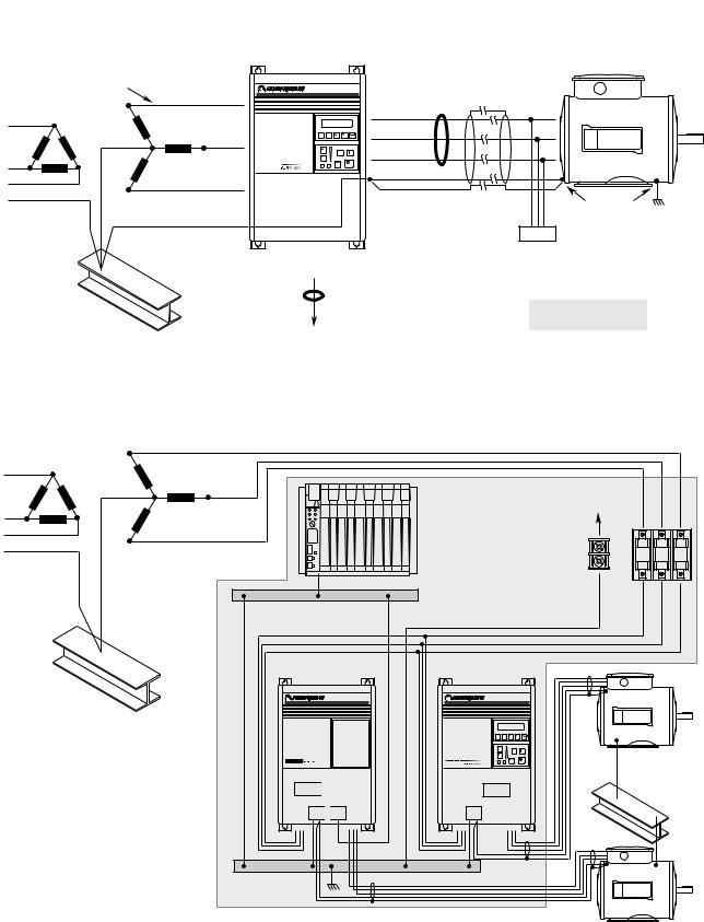
General Grounding
Conduit/4-Wire Cable |
|
|
|
Common |
|
|
|
|
|
|
Mode |
|
|
|
|
|
R (L1) |
|
|
|
|
|
|
|
|
|
Core* |
|
|
|
|
|
|
|
|
|
|
|
|
|
|
|
|
U (T1) |
|
|
|
|
S (L2) |
ESC SEL |
|
V (T2) |
|
|
|
|
|
|
W (T3) |
|
|
|
|
|
|
|
JOG |
|
|
|
|
|
T (L3) |
|
|
PE/Gnd. |
|
|
|
|
|
|
|
|
|
|
|
|
|
|
|
Shield |
|
Motor Frame |
|
|
PE |
|
|
|
|
PE |
|
|
|
|
|
|
|
||
|
|
|
|
|
|
Ground per |
|
|
|
RIO/DH+ |
|
|
Motor |
Local Codes |
|
|
|
or Analog |
|
|
Terminator* |
|
|
|
|
Common |
|
|
|
|
|
|
|
Mode Core* |
|
|
* Options that can be |
|
|
|
|
|
|
|
|
||
Nearest |
|
|
|
|
installed as needed. |
|
|
Building Structure Steel |
|
To Computer/Position Controller |
|
|
|
||
|
(for TE shield ground, see "Control and Signal Wiring") |
|
|
|
|||
Single-Point Grounding/Panel Layout
R (L1)
S (L2)
T (L3)
TE – Zero Volt Potential Bus
(Isolated from Panel)
1336 FORCE
Nearest
Building Structure Steel
Logic 

PE 
 TE
TE
To Nearest Building
Structure Steel
For Programmable Controller grounding recommendations, refer to publication 1770-4.1
1336 PLUS
ESC SEL
JOG
Nearest Building
Structure Steel
 Logic
Logic
PE
PE Ground Bus (Grounded to Panel)
Important: Grounding requirements will vary with the drives being used. Drives with True Earth (TE) terminals must have a zero potential bus, separate from potential earth (PE) ground bus. Note that buses can be tied together at one point in the control cabinet or brought back separately to the building ground grid (tied within 3 meters (10 feet)).
2–14 Installation/Wiring
Power Cabling |
Input and output power connections are performed through terminal |
|||||||||
|
block, TB1 (see Figure 2.1 for location). |
|||||||||
|
Important: For maintenance and setup procedures, the drive may be |
|||||||||
|
|
|
|
|
|
|
|
operated without a motor connected. |
||
|
Table 2.C |
|
|
|||||||
|
TB1 Signals |
|
|
|||||||
|
|
|
|
|
|
|
|
|
|
|
|
Terminal |
Description |
||||||||
|
|
|
|
|
|
|
|
|
|
|
|
PE |
|
|
|
|
|
|
Potential Earth Ground |
|
|
|
|
|||||||||
|
|
|
|
|
|
|
||||
|
|
|
|
|
|
|
||||
|
TE |
|
|
|
|
|
|
True Earth Ground |
|
|
|
|
|||||||||
|
|
|
|
|
|
|
|
|||
|
|
|
|
|
|
|
|
|||
|
R (L1), S (L2), T (L3) |
AC Line Input Terminals |
||||||||
|
+DC, -DC |
DC Bus Terminals |
||||||||
|
U (T1), V (T2), W (T3) |
Motor Connection |
||||||||
|
|
|
|
|
|
|
|
|
|
|
ATTENTION: The National Codes and standards (NEC,
!VDE, BSI etc.) and local codes outline provisions for safely installing electrical equipment. Installation must comply with specifications regarding wire types, conductor sizes, branch circuit protection and disconnect devices. Failure to do so may result in personal injury and/or equipment damage.
TB1 |
Power Terminal Block |
TB2 |
Control & Signal Wiring |
TB3 |
Control Interface Option |
TB4 |
24V DC Auxiliary Input |
TB6 |
High Voltage DC Auxiliary Input |
TB9 |
480 or 600V Auxiliary Output (F Frame Only) |
TE |
Control & Signal Shield Terminals |
|
TB3 |
Control Interface |
Option |
|
TB1 |
Frames A1-A4 1 |
|
|
|
TB4 |
|
|
TB6 |
TB2 |
Control Interface |
TB3 |
Option |
TB2 |
|
|
||
TB1 |
TB1 |
TB1 |
|
Frames B, C 1
Figure 2.1
Terminal Block Locations
|
TB3 |
Control Interface |
TB4 |
Option |
TB2 |
|
|
|
TE |
TB1 |
TB6 |
Location |
|
|
TB1 |
Frames D, E 1
R, S, T |
|
|
TB9 |
|
|
TB3 |
|
TB3 |
TB2 |
|
TB2 |
TE |
|
TE |
TB1 Location |
|
U, V, W |
TB1 |
TB1 |
|
|
& Brake |
|
|
Location |
|
|
|
Terminals |
Brake |
|
PE |
Terminals |
|
Ground |
Frame F 1 |
Frame G 1 |
|
1 Refer to page 1–1 for frame reference classifications and Figure 2.2 for TB1 details.

Installation/Wiring 2–15
Table 2.D
TB1 Specifications
Drive Frame |
Max./Min. Wire Size 1 |
Maximum Torque |
|
Size |
mm2 (AWG) |
N-m (lb.-in.) |
|
|
|
|
|
A1-A4 (page 2–21) |
5.3/0.8 (10/18) |
1.81 (16) |
|
B1 (page 2–21) |
8.4/0.8 (8/18) |
1.81 (16) |
|
B2 (page 2–21) |
13.3/0.5 (6/20) |
1.70 (15) |
|
C (page 2–21) |
26.7/0.8 (3/18) |
5.65 (50) |
|
D (page 2–22) 3, 4 |
120.0/2.1 (4/0 /14) |
6.00 (52) |
|
|
67.4/2.1 (00/14) 2 |
6.00 (52) |
|
E (page 2–22) 3, 5 |
253.0/2.1 (500 MCM/14) |
10.00 |
(87) |
F (page 2–23) 3 |
303.6/2.1 (600 MCM/14) |
23.00 |
(200) |
G (page 2–23) 3 |
303.6/2.1 (600 MCM/14) |
23.00 |
(200) |
1Wire sizes given are maximum/minimum sizes that TB1 will accept - these are not recommendations.Use Copper wire only. Wire gauge requirements and recommendations are based on 75 degree C. Do not reduce wire gauge when using higher temperature wire.
2Applies to 30 kW (40 HP) 200-240V, 45 & 56 kW (60 & 75 HP) 380-480V, 56 kW (75 HP) 500-600V drives only.
3These configurations of TB1 are stud type terminations and require the use of lug type connectors to terminate field installed conductors. Lug kits are available for use with these configurations. Wire size used is determined by selecting the proper lug based on the drive catalog number. Refer to Table 2.E.
4One TE terminal is present – Max./Min. Wire Size is the same as other terminals.
5Two TE terminals are present – Max./Min. Wire Size is the same as the D Frame terminal block.
Lug Kits
D, E, F and G Frame drives have stud type terminals and/or bus bars/ bolts that require standard “crimp type” connectors for cable termination. Connectors such as T & B Color-Keyed connectors (or equivalent) are recommended. The following table shows the lug selection for one possible cable choice. Connectors for each installation should be chosen based on desired cable sizes, the application requirements and all applicable national, state and local codes. See the minimum/ maximum values for wire size per Table 2.D

2–16 Installation/Wiring
Table 2.E
Lug Selection
|
AC Input R, S, T/Output U, V, W and PE |
DC+/DC– 2 |
|
|
TE |
|
|
|
|||||||
Drive Catalog |
Cable (per Phase) |
T&B Part No.3 |
Cable (per Phase) |
T&B Part No.3 |
Cable (per Phase) |
T&B Part No.3 |
|||||||||
Number |
Qty. mm2 (AWG) |
Qty. Number |
Qty. mm2 (AWG) |
Qty. Number |
Qty. mm2 (AWG) |
Qty. Number |
|||||||||
1336F-A040 |
(1) |
53.5 |
(1/0) |
(8) |
541531 |
(1) |
13.3 |
(6) |
(2) |
541351 |
(1) |
13.3 (6) |
(1) |
541351 |
|
1336F-A050 |
(1) |
85.0 |
(3/0) |
(8) |
541631 |
(1) |
13.3 |
(6) |
(2) |
541351 |
(1) |
13.3 (6) |
(1) |
541351 |
|
1336F-A060 |
(1) |
107.2 |
(4/0) |
(8) |
541681 |
(1) |
13.3 |
(6) |
(2) |
541351 |
(1) |
21.2 (4) |
(1) |
541391 |
|
1336F-A075 |
(2) |
53.5 |
(1/0) |
(8) |
54109T |
(1) |
33.6 |
(2) |
(2) |
54109 |
(1) |
21.2 (4) |
(1) |
541391 |
|
|
|
|
|
|
(8) |
54109B |
|
|
|
|
|
|
|
|
|
1336F-A100 |
(2) |
85.0 |
(3/0) |
(8) |
54111T |
(1) |
42.4 |
(1) |
(2) |
54148 |
(1) |
33.6 (2) |
(1) |
541421 |
|
|
|
|
|
|
(8) |
54111B |
|
|
|
|
|
|
|
|
|
1336F-A125 |
(2) |
107.2 |
(4/0) |
(8) |
54112T |
(1) |
67.4 |
(2/0) |
(2) |
54110 |
(1) |
33.6 (2) |
(1) |
541421 |
|
|
|
|
|
|
(8) |
54112B |
|
|
|
|
|
|
|
|
|
1336F-B060 |
(1) |
42.4 |
(1) |
(8) |
541471 |
(1) |
8.4 (8) |
(2) |
541311 |
(1) |
13.3 (6) |
(1) |
541351 |
||
1336F-B075 |
(1) |
53.5 |
(1/0) |
(8) |
541531 |
(1) |
13.3 |
(6) |
(2) |
541351 |
(1) |
13.3 (6) |
(1) |
541351 |
|
1336F-B100 |
(1) |
85.0 |
(3/0) |
(8) |
541631 |
(1) |
13.3 |
(6) |
(2) |
541351 |
(1) |
13.3 (6) |
(1) |
541351 |
|
1336F-B125 |
(1) |
107.2 |
(4/0) |
(8) |
541681 |
(1) |
26.7 |
(3) |
(2) |
541471 |
(1) |
21.2 (4) |
(1) |
541391 |
|
1336F-BX150 |
(1) |
107.2 |
(4/0) |
(8) |
541681 |
(1) |
26.7 |
(3) |
(2) |
541471 |
(1) |
21.2 (4) |
(1) |
541391 |
|
1336F-B150 |
(2) |
53.5 |
(1/0) |
(8) |
54109T |
(1) |
33.6 |
(2) |
(2) |
54110 |
(1) |
21.2 (4) |
(1) |
541391 |
|
|
|
|
|
|
(8) |
54109B |
|
|
|
|
|
|
|
|
|
1336F-B200 |
(2) |
85.0 |
(3/0) |
(8) |
54111T |
(1) |
42.4 |
(1) |
(2) |
54148 |
(1) |
26.7 (3) |
(1) |
541421 |
|
|
|
|
|
|
(8) |
54111B |
|
|
|
|
|
|
|
|
|
1336F-B250 |
(2) |
107.2 |
(4/0) |
(8) |
54112T |
(1) |
67.4 |
(2/0) |
(2) |
54110 |
(1) |
33.6 (2) |
(1) |
541421 |
|
|
|
|
|
|
(8) |
54112B |
|
|
|
|
|
|
|
|
|
1336F-BX250 |
(3) |
53.5 |
(1/0) |
(24) |
54109 |
(1) |
67.4 |
(2/0) |
(2) |
54110 |
NA |
|
NA |
|
|
1336F-BP/BPR250 |
(3) |
53.5 |
(1/0) |
(24) |
54109 |
(1) |
67.4 |
(2/0) |
(2) |
54110 |
NA |
|
NA |
|
|
1336F-B300 |
(3) |
67.4 |
(2/0) |
(24) |
54110 |
(1) |
42.4 |
(1) |
(2) |
54148 |
NA |
|
NA |
|
|
1336F-BP/BPR300 |
(3) |
67.4 |
(2/0) |
(24) |
54110 |
(1) |
42.4 |
(1) |
(2) |
54148 |
NA |
|
NA |
|
|
1336F-B350 |
(3) |
85.0 |
(3/0) |
(24) |
54111 |
(1) |
42.4 |
(1) |
(2) |
54148 |
NA |
|
NA |
|
|
1336F-BP/BPR350 |
(3) |
85.0 |
(3/0) |
(24) |
54111 |
(1) |
42.4 |
(1) |
(2) |
54148 |
NA |
|
NA |
|
|
1336F-B400 |
(3) |
107.2 |
(4/0) |
(24) |
54112 |
(1) |
42.4 |
(1) |
(2) |
54148 |
NA |
|
NA |
|
|
1336F-BP/BPR400 |
(3) |
107.2 |
(4/0) |
(24) |
54112 |
(1) |
42.4 |
(1) |
(2) |
54148 |
NA |
|
NA |
|
|
1336F-B450 |
(3) |
127.0 |
(250 MCM) |
(24) |
54174 |
(1) |
42.4 |
(1) |
(2) |
54148 |
NA |
|
NA |
|
|
1336F-BP/BPR450 |
(3) |
127.0 |
(250 MCM) |
(24) |
54174 |
(1) |
42.4 |
(1) |
(2) |
54148 |
NA |
|
NA |
|
|
1336F-B500 |
(3) |
152.0 |
(300 MCM) |
(24) |
54179 |
(1) |
53.5 |
(1/0) |
(2) |
54109 |
NA |
|
NA |
|
|
1336F-B600 |
(3) |
152.0 |
(300 MCM) |
(24) |
54179 |
(1) |
53.5 |
(1/0) |
(2) |
54109 |
NA |
|
NA |
|
|
1336F-C075 |
(1) |
33.6 |
(2) |
(8) |
541421 |
(1) |
13.3 |
(6) |
(2) |
541351 |
(1) |
8.4 (8) |
(1) |
541311 |
|
1336F-C100 |
(1) |
53.5 |
(1/0) |
(8) |
541531 |
(1) |
13.3 |
(6) |
(2) |
541351 |
(1) |
13.3 (6) |
(1) |
541351 |
|
1336F-C125 |
(1) |
67.4 |
(2/0) |
(8) |
541581 |
(1) |
26.7 |
(3) |
(2) |
541471 |
(1) |
13.3 (6) |
(1) |
541351 |
|
1336F-C150 |
(1) |
107.2 |
(4/0) |
(8) |
54111 |
(1) |
42.4 |
(1) |
(2) |
54148 |
(1) |
13.3 (6) |
(1) |
541351 |
|
1336F-C200 |
(2) |
67.4 |
(2/0) |
(8) |
54110T |
(1) |
42.4 |
(1) |
(2) |
54148 |
(1) |
26.7 (3) |
(1) |
541421 |
|
|
|
|
|
|
(8) |
54110B |
|
|
|
|
|
|
|
|
|
1336F-C250 |
(2) |
85.0 |
(3/0) |
(8) |
54111T |
(1) |
67.4 |
(2/0) |
(2) |
54110 |
(1) |
26.7 (3) |
(1) |
541421 |
|
|
|
|
|
|
(8) |
54111B |
|
|
|
|
|
|
|
|
|
1336F-CX300 |
(3) |
85.0 |
(3/0) |
(16) |
54111 |
|
|
|
|
|
NA |
|
NA |
|
|
1336F-C300 |
(3) |
85.0 |
(3/0) |
(16) |
54111 |
|
|
|
|
|
NA |
|
NA |
|
|
1336F-C350 |
(3) |
53.5 |
(1/0) |
(24) |
54109 |
|
|
|
|
|
NA |
|
NA |
|
|
1336F-C400 |
(3) |
67.4 |
(2/0) |
(24) |
54110 |
|
|
Consult Factory |
NA |
|
NA |
|
|||
1336F-C450 |
(3) |
85.0 |
(3/0) |
(24) |
54111 |
|
|
|
|
|
NA |
|
NA |
|
|
1336F-C500 |
(3) |
107.2 |
(4/0) |
(24) |
54112 |
|
|
|
|
|
NA |
|
NA |
|
|
1336F-C600 |
(3) |
127.0 |
(250 MCM) |
(24) |
54174 |
|
|
|
|
|
NA |
|
NA |
|
|
15/16” Stud. All other studs are 3/8”.
2Lugs shown for DC+/– are based on dynamic brake sizing of 50% of (motor rating X 1.25). Select proper lugs based on required braking torque. Refer to 1336-5.64 or 1336-5.65 for additional information.
3T & B COLOR-KEYED Connectors require T & B WT117 or TBM-6 Crimper tool or equivalent. Lugs should be crimped according to manufacturer’s tool instructions. If required, Rockwell Automation can supply lug kits for lugs shown above. Kits do not include crimping tools. Consult factory for kit information.

Installation/Wiring 2–17
Motor Cables
A variety of cable types are acceptable for drive installations. For many installations, unshielded cable is adequate, provided it can be separated from sensitive circuits. As an approximate guide, allow a spacing of 0.3 meters (1 ft.) for every 10 meters (32.8 ft.) of length. In all cases, long parallel runs must be avoided. Do not use cable with an insulation thickness less than or equal to 15 mils (0.4 mm/0.015 in.).
The cable should be 4-conductor with the ground lead being connected directly to the drive ground terminal (PE) and the motor frame ground terminal. See table below.
Unshielded
THHN, THWN or similar wire is acceptable for drive installation in dry environments provided adequate free air space and/or conduit fill rates limits are provided. Do not use THHN or similarly coated wire in wet areas. Any wire chosen must have a minimum insulation thickness of 15 mils and should not have large variations in insulation concentricity.
Shielded/Armored Cable
Shielded cable is recommended if sensitive circuits or devices are connected or mounted to the machinery driven by the motor (see table).
Recommended Shielded Wire
Location |
Rating/Type |
Description |
|
Standard |
600V, 90°C (194°F) |
• Four tinned copper conductors with XLP insulation. |
|
(Option 1) |
XHHW2/RHW-2 |
• Copper braid/aluminum foil combination shield and |
|
|
Anixter B209500- |
|
tinned copper drain wire. |
|
B209507, Belden 29501- |
• |
PVC jacket. |
|
29507, or equivalent |
|
|
Standard |
Tray rated 600V, 90° C |
• Three tinned copper conductors with XLPE insulation. |
|
(Option 2) |
(194° F) RHH/RHW-2 |
• 5 mil single helical copper tape (25% overlap min.) |
|
|
Anixter OLF-7xxxxx or |
|
with three bare copper grounds in contact with shield. |
|
equivalent |
• |
PVC jacket. |
Class I & II; |
Tray rated 600V, 90° C |
• Three bare copper conductors with XLPE insulation |
|
Division I & II |
(194° F) RHH/RHW-2 |
|
and impervious corrugated continuously welded alu- |
|
Anixter 7V-7xxxx-3G or |
|
minum armor. |
|
equivalent |
• Black sunlight resistant PVC jacket overall. |
|
|
|
• |
Three copper grounds on #10 AWG and smaller. |
Conduit
If metal conduit is preferred for cable distribution, the following guidelines must be followed.
•Drives are normally mounted in cabinets and ground connections are made at a common ground point in the cabinet. Normal installation of conduit provides grounded connections to both the motor frame ground (junction box) and drive cabinet ground. These ground connections help minimize interference. This is a noise reduction recommendation only, and does not affect the requirements for safety grounding (refer to pages 2–11 and 2–12).
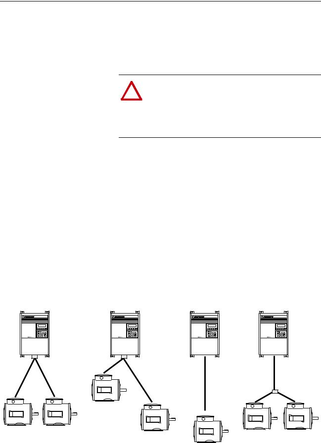
2–18 Installation/Wiring
•No more than three sets of motor leads can be routed through a single conduit. This will minimize “cross talk” that could reduce the effectiveness of the noise reduction methods described. If more than three drive/motor connections per conduit are required, shielded cable as described above must be used. If practical, each conduit should contain only one set of motor leads.
ATTENTION: To avoid a possible shock hazard caused by
!induced voltages, unused wires in the conduit must be grounded at both ends. For the same reason, if a drive sharing a conduit is being serviced or installed, all drives using this conduit should be disabled. This will eliminate the possible shock hazard from “cross coupled” drive motor leads.
Motor Lead Lengths
Installations with long cables to the motor may require the addition of output reactors or cable terminators to limit voltage reflections at the motor. Excessive cable charging current can also reduce the amount of current available to produce rated motor torque. Refer to Tables 2.F and 2.G for the maximum cable length allowed for various installation techniques. Shaded distances are restricted by cable capacitance charging current. The figure below demonstrates how total cable length is calculated. Failure to follow these guidelines can result in poor motor performance and nuisance drive overcurrent or overload tripping. For installations that exceed the recommended maximum lengths listed, contact the factory.
Please note that the cable lengths shown are guidelines. Your application may be restricted to a shorter cable length due to wire type, wire placement, line reactor and type of motor.
How to Measure Motor Cable Lengths Limited by Capacitance
91.4 (300) |
15.2 (50) |
|
|
|
|
|
152.4 (500) |
||
91.4 (300) |
167.6 (550) |
182.9 (600) |
||
|
||||
|
|
15.2 (50) |
15.2 (50) |
All examples represent motor cable length of 189.2 meters (600 feet).

|
|
|
|
|
|
|
|
|
|
|
|
Installation/Wiring |
2–19 |
||||
|
|
|
|
|
|
Table 2.F |
|
|
|
|
|
|
|
|
|
|
|
|
|
|
|
|
|
Maximum Motor Cable Length Restrictions in meters (feet) - 380V-480V Drives1 |
|||||||||||
|
|
|
No External Devices |
|
w/1204-TFB2 Term. |
w/1204-TFA1 Terminator |
|
Reactor at Drive2 |
|
||||||||
|
|
|
Motor |
|
|
|
Motor |
|
|
Motor |
|
|
|
|
Motor |
|
|
|
|
|
|
|
|
|
|
|
|
|
|
|
|
|
|
|
|
|
|
|
|
|
|
1600V or |
|
|
|
|
|
|
|
|
|
|
|
|
|
|
A |
B |
1329 |
1329R/L (1850V) |
A or B |
|
1329 |
A |
|
B |
|
1329 |
A |
B or 1329 |
|
|
|
|
|
|
|
|
|
|
|
|
|
|
|
|
|||
Drive |
Drive kW |
Motor kW |
Any |
Any |
Any |
Any |
Cable Type |
Any |
Cable Type |
Cable Type |
Any |
Any |
Any |
||||
Frame |
(HP) |
(HP) |
Cable |
Cable |
Cable |
Cable6 |
Shld.3 |
Unshld. |
Cable |
Shld.3 |
Unshld. |
Shld.3 |
Unshld. |
Cable |
Cable |
Cable |
|
A1 |
0.37 (0.5) |
0.37 (0.5) |
12.2 |
33.5 |
91.4 |
91.4 |
|
|
|
30.5 |
61.0 |
30.5 |
61.0 |
91.4 |
22.9 |
182.9 |
|
|
|
|
(40) |
(110) |
(300) |
(300) |
|
|
|
(100) |
(200) |
(100) |
(200) |
(300) |
(75) |
(600) |
|
|
0.75 (1) |
0.75 (1) |
12.2 |
33.5 |
91.4 |
91.4 |
|
|
|
30.5 |
30.5 |
30.5 |
30.5 |
91.4 |
22.9 |
182.9 |
|
|
|
|
(40) |
(110) |
(300) |
(300) |
|
|
|
(100) |
(100) |
(100) |
(100) |
(300) |
(75) |
(600) |
|
|
|
0.37 (0.5) |
12.2 |
33.5 |
91.4 |
91.4 |
Use |
1204-TFA1 |
30.5 |
61.0 |
30.5 |
61.0 |
91.4 |
22.9 |
182.9 |
|
|
|
|
|
(40) |
(110) |
(300) |
(300) |
|
|
|
(100) |
(200) |
(100) |
(200) |
(300) |
(75) |
(600) |
|
|
1.2 (1.5) |
1.2 (1.5) |
12.2 |
33.5 |
91.4 |
91.4 |
|
|
|
30.5 |
30.5 |
61.0 |
61.0 |
91.4 |
22.9 |
182.9 |
|
|
|
|
(40) |
(110) |
(300) |
(300) |
|
|
|
(100) |
(100) |
(200) |
(200) |
(300) |
(75) |
(600) |
|
|
|
0.75 (1) |
12.2 |
33.5 |
91.4 |
91.4 |
|
|
|
30.5 |
30.5 |
61.0 |
61.0 |
91.4 |
22.9 |
182.9 |
|
|
|
|
(40) |
(110) |
(300) |
(300) |
|
|
|
(100) |
(100) |
(200) |
(200) |
(300) |
(75) |
(600) |
|
|
|
0.37 (0.5) |
12.2 |
33.5 |
114.3 |
121.9 |
|
|
|
30.5 |
30.5 |
61.0 |
61.0 |
121.9 |
22.9 |
182.9 |
|
|
|
|
(40) |
(110) |
(375) |
(400) |
|
|
|
(100) |
(100) |
(200) |
(200) |
(400) |
(75) |
(600) |
|
A2 |
1.5 (2) |
1.5 (2) |
7.6 |
12.2 |
91.4 |
91.4 |
91.4 |
91.4 |
91.4 |
30.5 |
30.5 |
91.4 |
61.0 |
91.4 |
22.9 |
182.9 |
|
|
|
|
(25) |
(40) |
(300) |
(300) |
(300) |
(300) |
(300) |
(100) |
(100) |
(300) |
(200) |
(300) |
(75) |
(600) |
|
|
|
1.2 (1.5) |
7.6 |
12.2 |
114.3 |
182.9 |
91.4 |
182.9 |
182.9 |
30.5 |
30.5 |
91.4 |
61.0 |
182.9 |
22.9 |
182.9 |
|
|
|
|
(25) |
(40) |
(375) |
(600) |
(300) |
(600) |
(600) |
(100) |
(100) |
(300) |
(200) |
(600) |
(75) |
(600) |
|
|
|
0.75 (1) |
7.6 |
12.2 |
114.3 |
182.9 |
182.9 |
182.9 |
182.9 |
30.5 |
30.5 |
91.4 |
61.0 |
182.9 |
22.9 |
182.9 |
|
|
|
|
(25) |
(40) |
(375) |
(600) |
(600) |
(600) |
(600) |
(100) |
(100) |
(300) |
(200) |
(600) |
(75) |
(600) |
|
|
|
0.37 (0.5) |
7.6 |
12.2 |
114.3 |
182.9 |
182.9 |
182.9 |
182.9 |
30.5 |
30.5 |
91.4 |
61.0 |
182.9 |
22.9 |
182.9 |
|
|
|
|
(25) |
(40) |
(375) |
(600) |
(600) |
(600) |
(600) |
(100) |
(100) |
(300) |
(200) |
(600) |
(75) |
(600) |
|
|
2.2 (3) |
2.2 (3) |
7.6 |
12.2 |
91.4 |
91.4 |
182.9 |
182.9 |
182.9 |
|
|
|
|
|
22.9 |
182.9 |
|
|
|
|
(25) |
(40) |
(300) |
(300) |
(600) |
(600) |
(600) |
|
|
|
|
|
(75) |
(600) |
|
|
|
1.5 (2) |
7.6 |
12.2 |
114.3 |
182.9 |
182.9 |
182.9 |
182.9 |
|
|
|
|
|
22.9 |
182.9 |
|
|
|
|
(25) |
(40) |
(375) |
(600) |
(600) |
(600) |
(600) |
|
|
|
|
|
(75) |
(600) |
|
|
|
0.75 (1) |
7.6 |
12.2 |
114.3 |
182.9 |
182.9 |
182.9 |
182.9 |
|
|
|
|
|
22.9 |
182.9 |
|
|
|
|
(25) |
(40) |
(375) |
(600) |
(600) |
(600) |
(600) |
|
|
|
|
|
(75) |
(600) |
|
|
|
0.37 (0.5) |
7.6 |
12.2 |
114.3 |
182.9 |
182.9 |
182.9 |
182.9 |
|
|
|
|
|
22.9 |
182.9 |
|
|
|
|
(25) |
(40) |
(375) |
(600) |
(600) |
(600) |
(600) |
|
|
|
|
|
(75) |
(600) |
|
A3 |
3.7 (5) |
3.7 (5) |
7.6 |
12.2 |
114.3 |
182.9 |
182.9 |
182.9 |
182.9 |
|
|
|
|
|
22.9 |
182.9 |
|
|
|
|
(25) |
(40) |
(375) |
(600) |
(600) |
(600) |
(600) |
|
|
|
|
|
(75) |
(600) |
|
|
|
2.2 (3) |
7.6 |
12.2 |
114.3 |
Contact factory for |
182.9 |
182.9 |
182.9 |
|
|
|
|
|
22.9 |
182.9 |
|
|
|
|
(25) |
(40) |
(375) |
(600) |
(600) |
(600) |
|
|
|
|
|
(75) |
(600) |
|
|
|
|
|
|
|
|
advice on cable |
|
|
|
|
|
|
|
|
|
|
|
|
|
1.5 (2) |
7.6 |
12.2 |
114.3 |
182.9 |
182.9 |
182.9 |
|
|
|
|
|
22.9 |
182.9 |
|
|
|
|
|
(25) |
(40) |
(375) |
lengths over 182.9 |
(600) |
(600) |
(600) |
|
|
|
|
|
(75) |
(600) |
|
|
|
|
|
|
|
(600). |
|
|
|
|
|
|
|
|
|
|
|
|
|
0.75 (1) |
7.6 |
12.2 |
114.3 |
182.9 |
182.9 |
182.9 |
|
|
|
|
|
22.9 |
182.9 |
|
|
|
|
|
(25) |
(40) |
(375) |
|
(600) |
(600) |
(600) |
|
Use 1204-TFB2 |
|
(75) |
(600) |
|
||
|
|
0.37 (0.5) |
7.6 |
12.2 |
114.3 |
|
182.9 |
182.9 |
182.9 |
|
|
22.9 |
182.9 |
|
|||
|
|
|
|
|
|
|
|
|
|||||||||
|
|
|
(25) |
(40) |
(375) |
|
(600) |
(600) |
(600) |
|
|
|
|
|
(75) |
(600) |
|
A4 |
5.5-15 |
5.5-15 |
7.6 |
12.2 |
114.3 |
|
182.9 |
182.9 |
182.9 |
|
|
|
|
|
24.4 |
182.9 |
|
|
(7.5-20) |
(7.5-20) |
(25) |
(40) |
(375) |
|
(600) |
(600) |
(600) |
|
|
|
|
|
(80) |
(600) |
|
B |
11-22 |
11-22 |
7.6 |
12.2 |
114.3 |
|
182.9 |
182.9 |
182.9 |
|
|
|
|
|
24.4 |
182.9 |
|
|
(15-30) |
(15-30) |
(25) |
(40) |
(375) |
|
(600) |
(600) |
(600) |
|
|
|
|
|
(80) |
(600) |
|
C |
30-45 |
30-45 |
7.6 |
12.2 |
114.3 |
|
182.9 |
182.9 |
182.9 |
|
|
|
|
|
76.2 |
182.9 |
|
|
(X40-X60) |
(40-60) |
(25) |
(40) |
(375) |
|
(600) |
(600) |
(600) |
|
|
|
|
|
(250) |
(600) |
|
D |
45-112 |
45-112 |
12.2 |
30.5 |
114.3 |
|
182.9 |
182.9 |
182.9 |
|
|
|
|
|
61.0 |
182.9 |
|
|
(60-X150) |
(60-150) |
(40) |
(100) |
(375) |
|
(600) |
(600) |
(600) |
|
|
|
|
|
(200) |
(600) |
|
E |
112-187 |
112-187 |
12.2 |
53.3 |
114.3 |
|
182.9 |
182.9 |
182.9 |
|
|
|
|
|
182.9 |
182.9 |
|
|
(150-250) |
(150-250) |
(40) |
(175) |
(375) |
|
(600) |
(600) |
(600) |
|
|
|
|
|
(600) |
(600) |
|
F |
187-336 |
187-336 |
18.3 |
53.3 |
114.3 |
|
182.9 |
182.9 |
182.9 |
|
|
|
|
|
182.9 |
182.9 |
|
|
(250-450) |
(250-450) |
(60) |
(175) |
(375) |
|
(600) |
(600) |
(600) |
|
|
|
|
|
(600) |
(600) |
|
G |
187-448 |
187-448 |
18.3 |
53.3 |
114.3 |
|
182.9 |
182.9 |
182.9 |
|
|
|
|
|
182.9 |
182.9 |
|
|
(X250-600) |
(250-600) |
(60) |
(175) |
(375) |
|
(600) |
(600) |
(600) |
|
|
|
|
|
(600) |
(600) |
|
Type A Motor Characteristics: No phase paper or misplaced phase paper, lower quality insulation systems, corona inception voltages between 850 and 1000 volts. Type B Motor Characteristics: Properly placed phase paper, medium quality insulation systems, corona inception voltages between 1000 and 1200 volts.
1329R/L Motors: These AC variable speed motors are “Control-Matched” for use with Allen-Bradley Drives. Each motor is designed to meet or exceed the requirements of the Federal Energy Act of 1992. All 1329R/L motors are optimized for variable speed operation and include premium inverter grade insulation systems which meet or exceed NEMA MG1. Part 31.40.4.2.

2–20 Installation/Wiring
Table 2.G
Maximum Motor Cable Length Restrictions in meters (feet) - 500V-600V Drives4
|
|
|
No External Devices |
w/1204-TFB2 Terminator |
w/1204-TFA1 Terminator |
Reactor at Drive2 |
|
||||||||
|
|
|
Motor |
|
|
Motor |
|
|
Motor |
|
|
Motor |
|
|
|
|
|
|
|
|
|
|
|
|
|
|
|
|
|
|
|
|
|
|
|
|
|
|
|
1600V or |
|
|
1600V or |
|
|
|
1600V or |
|
|
|
|
|
1329R/L |
|
|
1329R/L |
|
|
1329R/L |
|
|
|
1329R/L |
|
|
|
A |
B |
Motors5 |
A |
B |
(1850V)5 |
A |
B |
(1850V)5 |
A |
|
B |
(1850V)5 |
Drive |
Drive kW |
Motor kW |
Any |
Any |
Any |
Any |
Any |
Any |
Any |
Any |
Any |
Any |
|
Any |
Any |
Frame |
(HP) |
(HP) |
Cable |
Cable |
Cable |
Cable |
Cable |
Cable |
Cable |
Cable |
Cable |
Cable |
|
Cable |
Cable |
A4 |
0.75 (1) |
0.75 (1) |
NR |
NR |
NA |
NR |
182.9 |
335.3 |
NR |
61.0 |
182.9 |
|
|
|
|
|
|
|
|
|
|
|
(600) |
(1100) |
|
(200) |
(600) |
|
|
|
|
|
|
0.37 (0.5) |
NR |
NR |
NA |
NR |
182.9 |
335.3 |
NR |
61.0 |
182.9 |
|
|
|
|
|
|
|
|
|
|
|
(600) |
(1100) |
|
(200) |
(600) |
|
|
|
|
|
1.5 (2) |
1.5 (2) |
NR |
NR |
NA |
NR |
182.9 |
335.3 |
NR |
61.0 |
182.9 |
|
|
|
|
|
|
|
|
|
|
|
(600) |
(1100) |
|
(200) |
(600) |
|
|
|
|
|
|
1.2 (1.5) |
NR |
NR |
NA |
NR |
182.9 |
335.3 |
NR |
61.0 |
182.9 |
|
|
|
|
|
|
|
|
|
|
|
(600) |
(1100) |
|
(200) |
(600) |
|
|
|
|
|
|
0.75 (1) |
NR |
NR |
182.9 |
NR |
182.9 |
335.3 |
NR |
61.0 |
182.9 |
|
|
|
|
|
|
|
|
|
(600) |
|
(600) |
(1100) |
|
(200) |
(600) |
|
|
|
|
|
|
0.37 (0.5) |
NR |
NR |
182.9 |
NR |
182.9 |
335.3 |
NR |
61.0 |
182.9 |
|
|
|
|
|
|
|
|
|
(600) |
|
(600) |
(1100) |
|
(200) |
(600) |
|
|
|
|
|
2.2 (3) |
2.2 (3) |
NR |
NR |
NA |
NR |
182.9 |
335.3 |
NR |
61.0 |
182.9 |
|
|
|
|
|
|
|
|
|
|
|
(600) |
(1100) |
|
(200) |
(600) |
|
|
|
|
|
|
1.5 (2) |
NR |
NR |
NA |
NR |
182.9 |
335.3 |
NR |
61.0 |
182.9 |
|
|
Not |
|
|
|
|
|
|
|
|
(600) |
(1100) |
|
(200) |
(600) |
|
Recommended |
||
|
|
0.75 (1) |
NR |
NR |
182.9 |
NR |
182.9 |
335.3 |
NR |
61.0 |
182.9 |
|
|
|
|
|
|
|
|
|
(600) |
|
(600) |
(1100) |
|
(200) |
(600) |
|
|
|
|
|
|
0.37 (0.5) |
NR |
NR |
182.9 |
NR |
182.9 |
335.3 |
NR |
61.0 |
182.9 |
|
|
|
|
|
|
|
|
|
(600) |
|
(600) |
(1100) |
|
(200) |
(600) |
|
|
|
|
|
3.7 (5) |
3.7 (5) |
NR |
NR |
NA |
NR |
182.9 |
335.3 |
NR |
61.0 |
182.9 |
|
|
|
|
|
|
|
|
|
|
|
(600) |
(1100) |
|
(200) |
(600) |
|
|
|
|
|
|
2.2 (3) |
NR |
NR |
NA |
NR |
182.9 |
335.3 |
NR |
61.0 |
182.9 |
|
|
|
|
|
|
|
|
|
|
|
(600) |
(1100) |
|
(200) |
(600) |
|
|
|
|
|
|
1.5 (2) |
NR |
NR |
182.9 |
NR |
182.9 |
335.3 |
NR |
61.0 |
182.9 |
|
|
|
|
|
|
|
|
|
(600) |
|
(600) |
(1100) |
|
(200) |
(600) |
|
|
|
|
|
|
0.75 (1) |
NR |
NR |
182.9 |
NR |
182.9 |
335.3 |
NR |
61.0 |
182.9 |
|
|
|
|
|
|
|
|
|
(600) |
|
(600) |
(1100) |
|
(200) |
(600) |
|
|
|
|
|
|
0.37 (0.5) |
NR |
NR |
182.9 |
NR |
182.9 |
335.3 |
NR |
61.0 |
182.9 |
|
|
|
|
|
|
|
|
|
(600) |
|
(600) |
(1100) |
|
(200) |
(600) |
|
|
|
|
|
5.5-15 |
5.5-15 |
NR |
9.1 |
182.9 |
91.4 |
182.9 |
182.9 |
NR |
61.0 |
182.9 |
30.5 |
|
91.4 |
182.9 |
|
(7.5-20) |
(7.5-20) |
|
(30) |
(600) |
(300) |
(600) |
(600) |
|
(200) |
(600) |
(100) |
|
(300) |
(600) |
C |
18.5-45 |
18.5-45 |
NR |
9.1 |
182.9 |
91.4 |
182.9 |
182.9 |
NR |
61.0 |
182.9 |
30.5 |
|
91.4 |
182.9 |
|
(25-60) |
(25-60) |
|
(30) |
(600) |
(300) |
(600) |
(600) |
|
(200) |
(600) |
(100) |
|
(300) |
(600) |
D |
56-93 |
56-93 |
NR |
9.1 |
182.9 |
91.4 |
182.9 |
182.9 |
NR |
61.0 |
182.9 |
61.0 |
|
91.4 |
182.9 |
|
(75-125) |
(75-125) |
|
(30) |
(600) |
(300) |
(600) |
(600) |
|
(200) |
(600) |
(200) |
|
(300) |
(600) |
E |
112-224 |
112-224 |
NR |
9.1 |
182.9 |
91.4 |
182.9 |
182.9 |
NR |
61.0 |
182.9 |
182.9 |
|
182.9 |
182.9 |
|
(150-X300) |
(150-X300) |
|
(30) |
(600) |
(300) |
(600) |
(600) |
|
(200) |
(600) |
(600) |
|
(600) |
(600) |
F |
261-298 |
261-298 |
NR |
9.1 |
182.9 |
91.4 |
182.9 |
182.9 |
NR |
61.0 |
182.9 |
182.9 |
|
182.9 |
182.9 |
|
(350-400) |
(350-400) |
|
(30) |
(600) |
(300) |
(600) |
(600) |
|
(200) |
(600) |
(600) |
|
(600) |
(600) |
G |
224-448 |
224-448 |
NR |
9.1 |
182.9 |
91.4 |
182.9 |
182.9 |
NR |
61.0 |
182.9 |
182.9 |
|
182.9 |
182.9 |
|
(300-600) |
(300-600) |
|
(30) |
(600) |
(300) |
(600) |
(600) |
|
(200) |
(600) |
(600) |
|
(600) |
(600) |
NR = Not Recommended
NA = Not Available at time of printing
1Values shown are for 480V nominal input voltage, drive carrier frequency of 2 kHz and ambient temperature at the motor of 40 degrees C. Consult factory regarding operation at carrier frequencies above 2 kHz. Multiply values by 0.85 for high line conditions. For input voltages of 380, 400 or 415V AC, multiply the table values by 1.25, 1.20 or 1.15, respectively.
2A 3% reactor reduces motor and cable stress but may cause a degradation of motor waveform quality. Reactors must have a turn-turn insulation rating of 2100 volts or higher.
3Includes wire in conduit.
4Values shown are for nominal input voltage and drive carrier frequency of 2 kHz. Consult factory regarding operation at carrier frequencies above 2 kHz. Multiply values by 0.85 for high line conditions.
5When used on 600V systems, 1329R/L motors have a corona inception voltage rating of approximately 1850V.
6These distance restrictions are due to charging of cable capacitance and may vary from application to application.
Loading...