


1756-HYD02
Table of contents
 Loading...
ControlLogix Hydraulic
Servo Module
User Manual
Catalog Numbers
1756-HYD02
Important User Information
Solid state equipment has operational characteristics differing from those of electromechanical equipment. Safety Guidelines for the
Application, Installation and Maintenance of Solid State Controls (publication SGI-1.1 available from your local Rockwell Automation sales
office or online at http://literature.rockwellautomation.com
wired electromechanical devices. Because of this difference, and also because of the wide variety of uses for solid state equipment, all
persons responsible for applying this equipment must satisfy themselves that each intended application of this equipment is acceptable.
In no event will Rockwell Automation, Inc. be responsible or liable for indirect or consequential damages resulting from the use or
application of this equipment.
The examples and diagrams in this manual are included solely for illustrative purposes. Because of the many variables and requirements
associated with any particular installation, Rockwell Automation, Inc. cannot assume responsibility or liability for actual use based on the
examples and diagrams.
No patent liability is assumed by Rockwell Automation, Inc. with respect to use of information, circuits, equipment, or software described in
this manual.
Reproduction of the contents of this manual, in whole or in part, without written permission of Rockwell Automation, Inc., is prohibited.
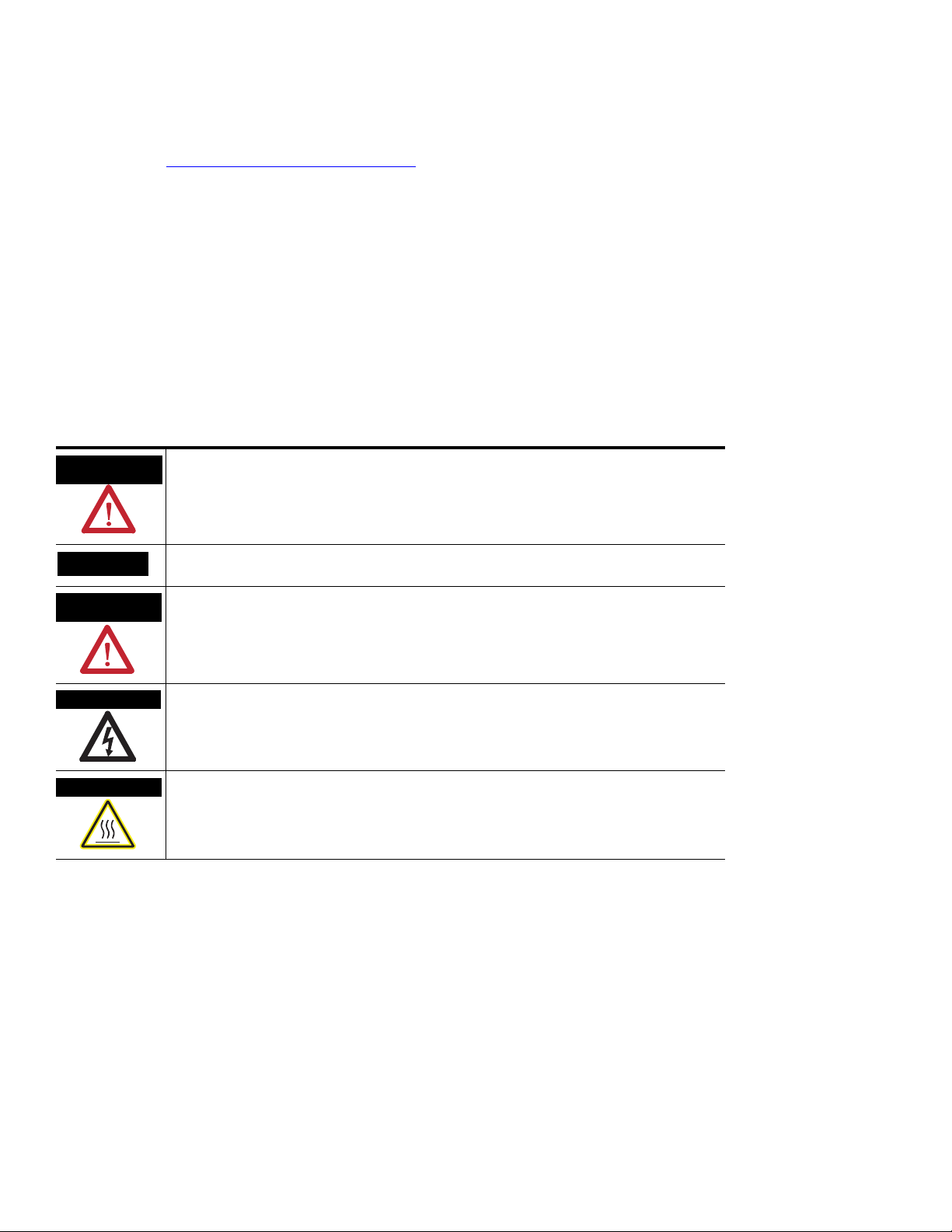
Throughout this manual, when necessary, we use notes to make you aware of safety considerations.
) describes some important differences between solid state equipment and hard-
WARNING
Identifies information about practices or circumstances that can cause an explosion in a
hazardous environment, which may lead to personal injury or death, property damage, or
economic loss.
IMPORTANT
ATTENTION
Identifies information that is critical for successful application and understanding of the product.
Identifies information about practices or circumstances that can lead to personal injury or death,
property damage, or economic loss. Attentions help you identify a hazard, avoid a hazard, and
recognize the consequence
SHOCK HAZARD
Labels may be on or inside the equipment, for example, a drive or motor, to alert people that
dangerous voltage may be present.
BURN HAZARD
Labels may be on or inside the equipment, for example, a drive or motor, to alert people that
surfaces may reach dangerous temperatures.
Allen-Bradley, Rockwell Automation, and TechConnect are trademarks of Rockwell Automation, Inc.
Trademarks not belonging to Rockwell Automation are property of their respective companies.

Table of Contents
Preface
What is the 1756-HYD02 Module?
Installing the 1756-HYD02 Module
Using This Manual . . . . . . . . . . . . . . . . . . . . . . . . . . . . . . . . . . . . . . . . . . 7
Who Should Use This Manual. . . . . . . . . . . . . . . . . . . . . . . . . . . . . . . . . 7
The Purpose of This Manual. . . . . . . . . . . . . . . . . . . . . . . . . . . . . . . . . . 7
Related Documentation . . . . . . . . . . . . . . . . . . . . . . . . . . . . . . . . . . . . . . 8
Chapter 1
What the Module Does . . . . . . . . . . . . . . . . . . . . . . . . . . . . . . . . . . . . . . 9
Using A ControlLogix Hydraulic Servo Module in the
ControlLogix System . . . . . . . . . . . . . . . . . . . . . . . . . . . . . . . . . . . . . . . 10
Physical Features of the ControlLogix Hydraulic Servo Module . 10
Certifying Agency Approvals. . . . . . . . . . . . . . . . . . . . . . . . . . . . . . . . . 11
Full Class I Division 2 Compliance. . . . . . . . . . . . . . . . . . . . . . . . . 11
Preventing Electrostatic Discharge . . . . . . . . . . . . . . . . . . . . . . . . . . . . 12
Removal and Insertion Under Power . . . . . . . . . . . . . . . . . . . . . . . . . . 12
Chapter Summary and What’s Next . . . . . . . . . . . . . . . . . . . . . . . . . . . 12
Chapter 2
What This Chapter Contains . . . . . . . . . . . . . . . . . . . . . . . . . . . . . . . . . 13
Note the Power Requirements . . . . . . . . . . . . . . . . . . . . . . . . . . . . . . . 13
Installing the Module . . . . . . . . . . . . . . . . . . . . . . . . . . . . . . . . . . . . . . . 14
Keying the Removable
Terminal Block. . . . . . . . . . . . . . . . . . . . . . . . . . . . . . . . . . . . . . . . . . . . 15
Connecting Wiring . . . . . . . . . . . . . . . . . . . . . . . . . . . . . . . . . . . . . . . . . 16
Two Types of RTBs (each RTB comes with housing) . . . . . . . . . 16
Wiring the 1756-HYD02 Module . . . . . . . . . . . . . . . . . . . . . . . . . . . . . 18
Wiring Registration Sensors . . . . . . . . . . . . . . . . . . . . . . . . . . . . . . 19
Wiring the Home Limit Switch Input. . . . . . . . . . . . . . . . . . . . . . . 20
Wiring the OK Contacts . . . . . . . . . . . . . . . . . . . . . . . . . . . . . . . . . 20
Connecting LDTs to Your Hydraulic Module . . . . . . . . . . . . . . . . 21
Assembling The Removable Terminal Block and the Housing. . . . . . 23
Choosing the Extended-Depth Housing . . . . . . . . . . . . . . . . . . . . . . . 24
Suggestions for Using the Extended-Depth Housing . . . . . . . . . . 25
Cabinet Size Considerations With the
Extended-Depth Housing . . . . . . . . . . . . . . . . . . . . . . . . . . . . . . . . 25
Installing the Removable Terminal Block. . . . . . . . . . . . . . . . . . . . . . . 26
Removing the Removable Terminal Block . . . . . . . . . . . . . . . . . . . . . . 28
Removing the Module from the Chassis. . . . . . . . . . . . . . . . . . . . . . . . 29
Chapter Summary and What’s Next . . . . . . . . . . . . . . . . . . . . . . . . . . . 30
3Publication 1756-UM525A-EN-P - June 2003 3

Table of Contents
Configuring the 1756-HYD02
Module
Using the 1756-HYD02 Module
Features
Chapter 3
Using RSLogix 5000 Configuration Software. . . . . . . . . . . . . . . . . . . . 31
Overview of the Configuration Process . . . . . . . . . . . . . . . . . . . . . . . . 32
Creating a New Module . . . . . . . . . . . . . . . . . . . . . . . . . . . . . . . . . . . . . 33
Configuring General Module Features . . . . . . . . . . . . . . . . . . . . . . . . . 35
Configuring the Axes Features . . . . . . . . . . . . . . . . . . . . . . . . . . . . . . . 36
Downloading New Configuration Data . . . . . . . . . . . . . . . . . . . . . . . . 37
Editing Configuration . . . . . . . . . . . . . . . . . . . . . . . . . . . . . . . . . . . . . . 38
Reconfiguring Module Parameters in Run Mode . . . . . . . . . . . . . . . . . 39
Reconfiguring Module Parameters in Program Mode . . . . . . . . . . . . . 39
Chapter Summary and What’s Next . . . . . . . . . . . . . . . . . . . . . . . . . . . 40
Chapter 4
What This Chapter Contains . . . . . . . . . . . . . . . . . . . . . . . . . . . . . . . . . 42
Using General Module Features . . . . . . . . . . . . . . . . . . . . . . . . . . . . . . 42
Servo Update Period . . . . . . . . . . . . . . . . . . . . . . . . . . . . . . . . . . . . 42
Module Fault Reporting . . . . . . . . . . . . . . . . . . . . . . . . . . . . . . . . . 43
Fully Software Configurable . . . . . . . . . . . . . . . . . . . . . . . . . . . . . . 43
Electronic Keying . . . . . . . . . . . . . . . . . . . . . . . . . . . . . . . . . . . . . . 44
Using Axes Features. . . . . . . . . . . . . . . . . . . . . . . . . . . . . . . . . . . . . . . . 52
General Tab . . . . . . . . . . . . . . . . . . . . . . . . . . . . . . . . . . . . . . . . . . . 52
Motion Planner Tab. . . . . . . . . . . . . . . . . . . . . . . . . . . . . . . . . . . . . 54
Units Tab . . . . . . . . . . . . . . . . . . . . . . . . . . . . . . . . . . . . . . . . . . . . . 56
Servo Tab . . . . . . . . . . . . . . . . . . . . . . . . . . . . . . . . . . . . . . . . . . . . . 57
Feedback Tab. . . . . . . . . . . . . . . . . . . . . . . . . . . . . . . . . . . . . . . . . . 58
Conversion Tab . . . . . . . . . . . . . . . . . . . . . . . . . . . . . . . . . . . . . . . . 59
Homing Tab. . . . . . . . . . . . . . . . . . . . . . . . . . . . . . . . . . . . . . . . . . . 60
Hookup Tab. . . . . . . . . . . . . . . . . . . . . . . . . . . . . . . . . . . . . . . . . . . 62
Tune Tab . . . . . . . . . . . . . . . . . . . . . . . . . . . . . . . . . . . . . . . . . . . . . 63
Dynamics Tab . . . . . . . . . . . . . . . . . . . . . . . . . . . . . . . . . . . . . . . . . 64
Gains Tab. . . . . . . . . . . . . . . . . . . . . . . . . . . . . . . . . . . . . . . . . . . . . 65
Output Tab. . . . . . . . . . . . . . . . . . . . . . . . . . . . . . . . . . . . . . . . . . . . 68
Limits Tab . . . . . . . . . . . . . . . . . . . . . . . . . . . . . . . . . . . . . . . . . . . . 70
Offset Tab . . . . . . . . . . . . . . . . . . . . . . . . . . . . . . . . . . . . . . . . . . . . 72
Fault Actions Tab . . . . . . . . . . . . . . . . . . . . . . . . . . . . . . . . . . . . . . 74
Tag Tab . . . . . . . . . . . . . . . . . . . . . . . . . . . . . . . . . . . . . . . . . . . . . . 76
Chapter Summary and What’s Next . . . . . . . . . . . . . . . . . . . . . . . . . . . 76
4 Publication 1756-UM525A-EN-P - June 2003

Troubleshooting the 1756-HYD02
Module
Specifications
Glossary
Table of Contents
Chapter 5
What This Chapter Contains . . . . . . . . . . . . . . . . . . . . . . . . . . . . . . . . . 77
Using the Status Indicators . . . . . . . . . . . . . . . . . . . . . . . . . . . . . . . . . . 77
Using the OK Indicator. . . . . . . . . . . . . . . . . . . . . . . . . . . . . . . . . . . . . 78
Using the FDBK Indicator . . . . . . . . . . . . . . . . . . . . . . . . . . . . . . . . . . 79
Using the DRIVE Indicator . . . . . . . . . . . . . . . . . . . . . . . . . . . . . . . . . 80
Using RSLogix 5000 to Troubleshoot the Module. . . . . . . . . . . . . . . . 81
Warning Signal in Controller Organizer . . . . . . . . . . . . . . . . . . . . . 81
Fault Message in Status Line . . . . . . . . . . . . . . . . . . . . . . . . . . . . . . 82
Notification in Axis Structure . . . . . . . . . . . . . . . . . . . . . . . . . . . . . 82
Chapter Summary and What’s Next . . . . . . . . . . . . . . . . . . . . . . . . . . . 82
Appendix A
Index
Publication 1756-UM525A-EN-P - June 2003 5

Table of Contents
6 Publication 1756-UM525A-EN-P - June 2003
Preface
Using This Manual
Who Should Use This
This preface describes how to use this manual.
To effectively use this manual, you should be able to program and operate the
Rockwell Automation ControlLogix controllers to efficiently use your
Manual
ControlLogix Hydraulic Servo module. In this manual, we also refer to the
module as the 1756-HYD02 module.
If you need more information about programming and operating the
ControlLogix controllers, refer to the Logix5000 Controller User Manual,
publication number
The Purpose of This Manual
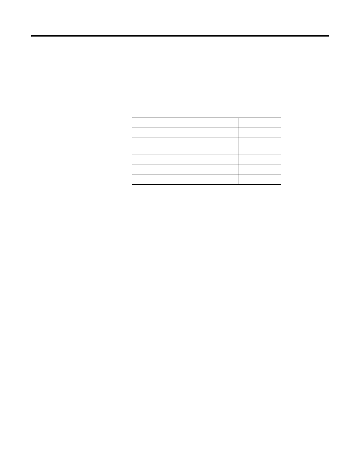
This manual describes how to set up, configure and troubleshoot your
1756-HYD02 module. The following table lists describes each section in this
manual:
1756-UM001
If you are looking for this information: See this section
Description of the module and what it does. Chapter 1
.
What is the 1756-HYD02 Module?
Step by step description of how to install and
wire the module.
Description of how to use RSLogix 5000
programming software to configure the
module.
Complete listing of the module’s features,
including the general module features and
features that specifically affect the data
coming from axes connected to either of the
module’s channels.
Description of how to troubleshoot any
problems with the module, including the use
of status indicators on the module and
software fault messages in RSLogix 5000.
Specifications for the module. Appendix A
Chapter 2
Installing the 1756-HYD02 Module
Chapter 3
Configuring the 1756-HYD02 Module
Chapter 4
Using the 1756-HYD02 Module Features
Chapter 5
Troubleshooting the 1756-HYD02 Module
Specifications
7Publication 1756-UM525A-EN-P - June 2003 7
Preface Preface
Related Documentation
Publication
Number
1756-IN580
1756-IN080
1756-IN613
1756-IN573
1756-IN574
1756-UM001
1756-RM003
The following table lists related ControlLogix documentation:
Publication Description
ControlLogix Hydraulic Servo Module
Installation Instructions
ControlLogix Chassis Installation Instructions Provides instructions for installing a
ControlLogix Power Supply Installation
Instructions
ControlLogix Redundant Power Supply
Installation Instructions
ControlLogix Redundant Power Supply Chassis
Adapter Module Installation Instructions
Logix5000 Controller User Manual Provides information for using your Logix5000
Logix5000 Controller Instruction Set Reference
Manual
Provides instructions for installing, wiring, and
troubleshooting your 1756-HYD02 module.
ControlLogix chassis
Provides instructions for installing a
ControlLogix power supply
Provides instructions for installing a
ControlLogix redundant power supply
Provides instructions for installing a
ControlLogix redundant power supply chassis
adapter module
controller and its components.
Provides descriptions of all the instructions
supported by the RSLogix 5000 programming
software.
To view or order the publications listed above, visit:
• http://literature.rockwellautomation.com
8 Publication 1756-UM525A-EN-P - June 2003
Chapter
What is the 1756-HYD02 Module?
This chapter describes the ControlLogix Hydraulic Servo module.
For more information about: See page:
What the Module Does 9
1
What the Module Does
Using A ControlLogix Hydraulic Servo Module in
the ControlLogix System
Certifying Agency Approvals 11
Preventing Electrostatic Discharge 12
Removal and Insertion Under Power 12
THe 1756-HYD02 module is typically used for accurate positioning and
control of a hydraulic cylinder. The module can be wired to a linear
displacement transducer (LDT) for feedback and a proportional or servo valve
for control of a hydraulic axis and connects to a hydraulic system to close a
high-speed position loop. Each Logix controller can support up to 16
1756-HYD02 modules. Each 1756-HYD02 module can control up to two
axes.
The 1756-HYD02 module monitors the position feedback via the linear
displacement transducer (LDT) input and generates an analog command
reference for the valve to make sure that the actuator (cylinder) follows the
profile. The 1756-HYD02 module closes the position loop at a programmed
rate using position feedback as the input and produces a +/-10V analog
output velocity command.
10
The module is programmed with motion instructions in the RSLogix 5000
programming software and must be in the same chassis as the ControlLogix
controller that controls the module. If you distribute motion control that uses
the 1756-HYD02 module across different locations, place a ControlLogix
controller in each chassis that has a 1756-HYD02 module. In this case, use a
1756-SYNCH module to synchronize motion between the multiple chassis.
Transducers connected to the 1756-HYD02 must accept external
interrogation signals. In this case, the transducer generates its position
information each time that it receives an interrogation pulse. Do not use
transducers configured for internal interrogation because they will not be
properly synchronized to the module.
9Publication 1756-UM525A-EN-P - June 2003 9
Chapter 1 What is the 1756-HYD02 Module?
Using A ControlLogix Hydraulic Servo Module in the ControlLogix System
A ControlLogix Hydraulic Servo module mounts in a ControlLogix chassis
and uses a removable terminal block (RTB) or interface module (IFM) to
connect all field-side wiring.
Before you install and use your module you should have already:
• installed and grounded a ControlLogix chassis and power supply. To
install these products, refer to the publications listed in on page 7.
• ordered and received an RTB or IFM and its components for your
application.
IMPORTANT
RTBs and IFMs are not included with your module purchase.
You must order them separately. For more information, contact
your local distributor or Rockwell Automation representative.
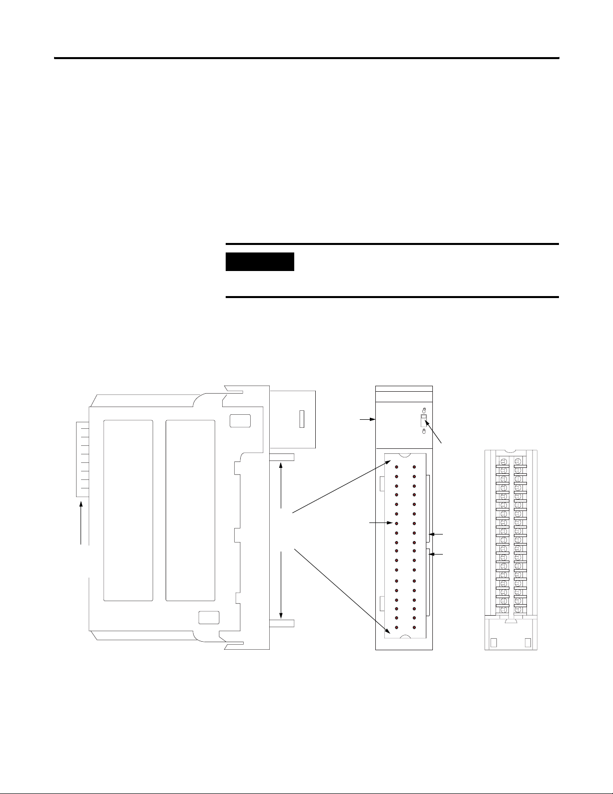
Physical Features of the ControlLogix Hydraulic Servo Module
ControlLogix
Backplane
Connector
Top and
bottom
guides
Indicators
Connector
pins
Removable
Terminal
Block
Locking tab
Slots for
keying the
RTB
41623
10 Publication 1756-UM525A-EN-P - June 2003
What is the 1756-HYD02 Module? Chapter 1
The table below lists the physical features on the ControlLogix Hydraulic
Servo module.
ControlLogix Hydraulic Servo Module Physical Features
Feature: Description:
ControlLogix backplane
connector
Connectors pins Input/output and grounding connections are made to the
Locking tab The locking tab anchors the RTB on the module, maintaining
Slots for keying Slots mechanically key the RTB to prevent you from making
Status indicators Indicators display the status of communication, module
Top and bottom guides Guides provide assistance in seating the RTB onto the
The interface to the ControlLogix system; it connects the
module to the backplane.
module through these pins with the use of an RTB.
wiring connections.
the wrong wire connections to your module.
health and presence of input/output devices. Use these
indicators to help in troubleshooting.
module.
Certifying Agency Approvals
If the ControlLogix Hydraulic Servo module has obtained any agency
approvals, for example, CE/CSA/UL, the module label is marked as such.
Full Class I Division 2 Compliance
The ControlLogix Hydraulic Servo module maintains CSA Class I Division 2
system certification. The module can be placed in an environment other than
only 100% hazard free.
IMPORTANT
The 1756-HYD02 module should not be pulled under power, nor
should a powered RTB be removed, in a Class I Division 2
environment.
Publication 1756-UM525A-EN-P - June 2003 11
Chapter 1 What is the 1756-HYD02 Module?
Preventing Electrostatic Discharge
Removal and Insertion Under Power
The 1756-HYD02 module is sensitive to electrostatic discharge.
ATTENTION
You can install or remove the module while chassis power is applied if you
observe the following precautions.
This equipment is sensitive to electrostatic discharge, which
can cause internal damage and affect normal operation. Follow
these guidelines when you handle this equipment:
• Touch a grounded object to discharge potential static.
• Wear an approved grounding wriststrap.
• Do not touch connectors or pins on component boards.
• Do not touch circuit components inside the equipment.
• If available, use a static-safe workstation.
• When not in use, store the equipment in appropriate static-safe
packaging.
Chapter Summary and What’s Next
WARNING
Repeated electrical arcing causes excessive wear to contacts on both the
module and its mating connector. Worn contacts may create electrical
resistance that can affect module operation.
We do not recommend removing and inserting the 1756-HYD02 module
while under power if the servo loop is closed. Make sure the servo loop is
open, that is, flashing green feedback indicator, before removing or inserting
the module under power.
In this chapter, you read a description of the 1756-HYD02 module. Chapter 2
describes
Installing the 1756-HYD02 Module
When you insert or remove the module while backplane power
is on, an electrical arc can occur. This could cause an explosion
in hazardous location installations. Be sure that power is
removed or the area is nonhazardous before proceeding.
However, as stated on the previous page, the 1756-HYD02
module should not be pulled under power, nor should a powered
RTB be removed, in a Class I Division 2 environment.
.
12 Publication 1756-UM525A-EN-P - June 2003

Installing the 1756-HYD02 Module
Chapter
2
What This Chapter Contains
This chapter describes how to install the 1756-HYD02 module.
The 1756-HYD02 module mounts in a ControlLogix chassis and uses a
removable terminal block (RTB) to connect all field-side wiring.
Before you install your module, make sure you:
For information about: See page:
Installing the Module 14
Keying the Removable Terminal Block 15
Connecting Wiring 16
Assembling The Removable Terminal Block and
the Housing
Installing the Removable Terminal Block 26
Removing the Removable Terminal Block 28
Removing the Module from the Chassis 29
• install and ground a ControlLogix chassis and power supply.
• order and receive an RTB, and its components, for your application.
23
For more information on all the ControlLogix chassis and power supplies, see
Note the Power
the ControlLogix Selection Guide, publication
This module receives power from the 1756 chassis power supply and requires
two sources of power from the backplane:
1756-SG001
.
Requirements
• 700mA at 5.1V
• 2.5 mA at 24V
Add this current to the requirements of all other modules in this chassis to
prevent overloading the backplane power supply.
13Publication 1756-UM525A-EN-P - June 2003 13
Chapter 2 Installing the 1756-HYD02 Module
Installing the Module
You can install or remove the module while chassis power is applied.
ATTENTION
The module is designed to support Removal and Insertion Under
Power (RIUP). However, when you remove or insert an RTB with
field-side power applied, unintended machine motion or
loss of process control can occur. Exercise extreme caution
when using this feature.
1. Align circuit board with top and bottom chassis guides.
Printed Circuit Board
20861-M
2. Slide module into chassis until module tabs ‘click’.
Locking Tab
20862-M
14 Publication 1756-UM525A-EN-P - June 2003
Installing the 1756-HYD02 Module Chapter 2
Keying the Removable Terminal Block
Key the RTB to prevent inadvertently connecting the incorrect RTB to your
module. When the RTB mounts onto the module, keyed positions match up.
For example, if you place a U-shaped keying band in position #4 on the
module, you cannot place a wedge-shaped tab in #4 on the RTB or your RTB
will not mount on the module.
Use a unique keying pattern for each slot in the chassis.
1. Insert the U-shaped band with the long side near the terminals.
2. Push the band onto the module until it snaps in place.
U-shaped
Keying Band
20850-M
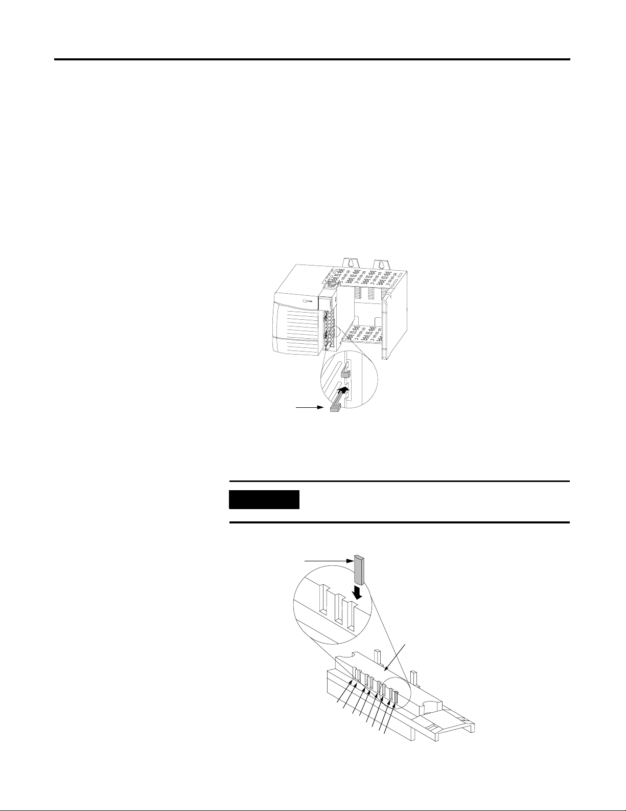
3. Key the RTB in positions that correspond to unkeyed module positions.
Insert the wedge-shaped tab on the RTB with the rounded edge first.
Push the tab onto the RTB until it stops.
IMPORTANT
When keying your RTB and module, you must begin with a
wedge-shaped tab in position #6 or #7.
Wedge–shaped
Keying Tab
Module side of RTB
0
1
2
3
4
5
6
7
Publication 1756-UM525A-EN-P - June 2003 15
20851–M
Chapter 2 Installing the 1756-HYD02 Module
Connecting Wiring
This module uses an RTB or a Bulletin 1492 Interface Module (IFM)
(1)
to
connect all field-side wiring. Use an extended-depth cover (1756-TBE) for
applications with heavy gauge wiring or requiring additional routing space. The
maximum wire gauge that can be used with the 1756-HYD02 module is #14
AWG (2.08 sq. mm) stranded.
If you are using an RTB to connect wiring to you module, follow the directions
beginning below.
An IFM has been prewired before you received it. If you are using an IFM to
connect wiring to the module, consult the documentation that came with it to
connect wiring, skip this section and move to page 23.
Two Types of RTBs (each RTB comes with housing)
• Cage Clamp - Catalog number 1756-TBCH
• Spring Clamp - Catalog number 1756-TBSH or TBS6H
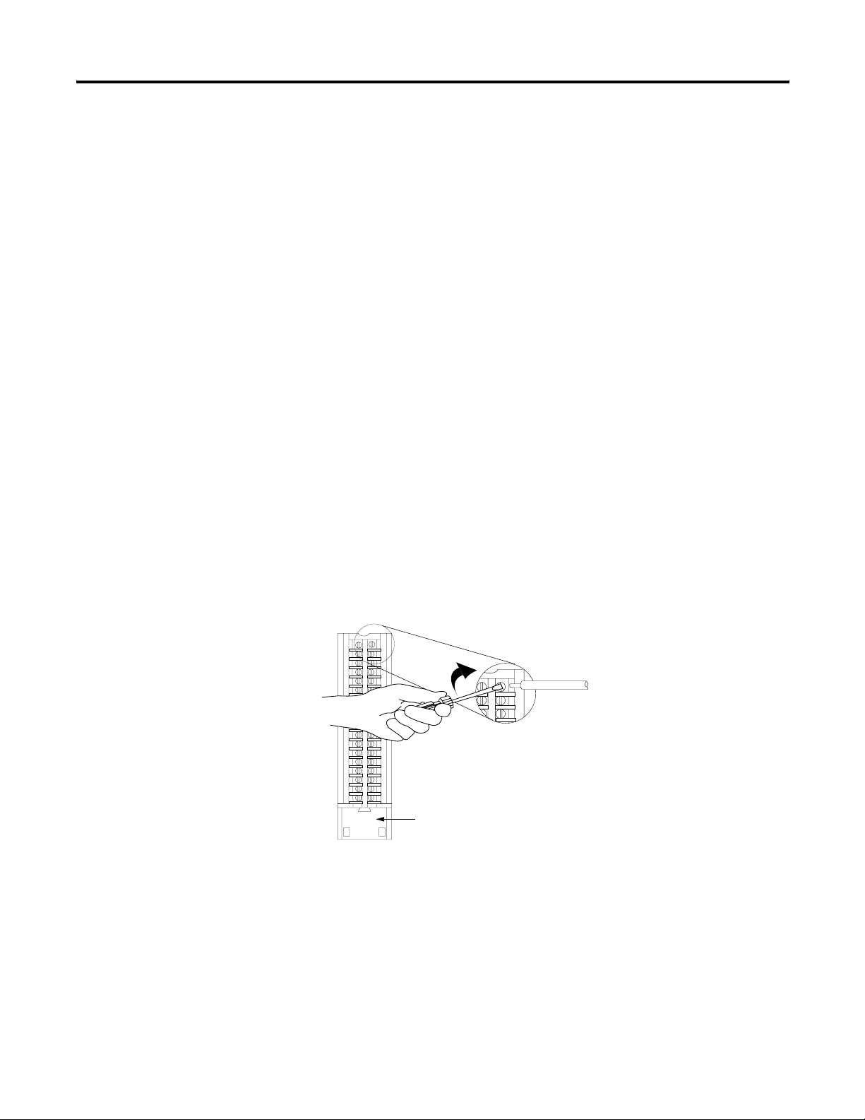
Cage Clamp
1. Insert the wire into the terminal.
2. Turn the screw clockwise to close the terminal on the wire.
Strain relief area
20859-M
(1)
The Bulletin 1492 IFM may not be used in any application that requires agency certification of the ControlLogix
system. Use of the IFM violates the UL, CSA and FM certifications of this product.
16 Publication 1756-UM525A-EN-P - June 2003
Installing the 1756-HYD02 Module Chapter 2
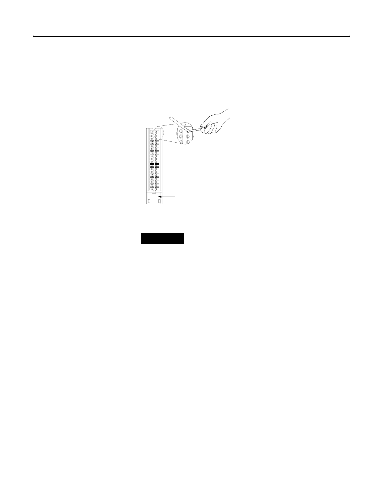
Spring Clamp
1. Insert the screwdriver into the outer hole of the RTB.
2. Insert the wire into the open terminal and remove the screwdriver.
Strain relief area
20860-M
Recommendations for Wiring Your RTB
TIP
Consider the following when wiring your RTB:
• Begin wiring the RTB at the bottom terminals and move up.
• Use a tie to secure the wires in the strain relief area of the RTB.
• The jumper bar part number is 97739201. Contact your local
Rockwell Automation sales representative to order additional
jumper bars, if necessary.
• Order and use an extended-depth housing, that is cat.
no.1756-TBE, for applications that require heavy gauge wiring. For
more information, see page 24.
Publication 1756-UM525A-EN-P - June 2003 17
Chapter 2 Installing the 1756-HYD02 Module
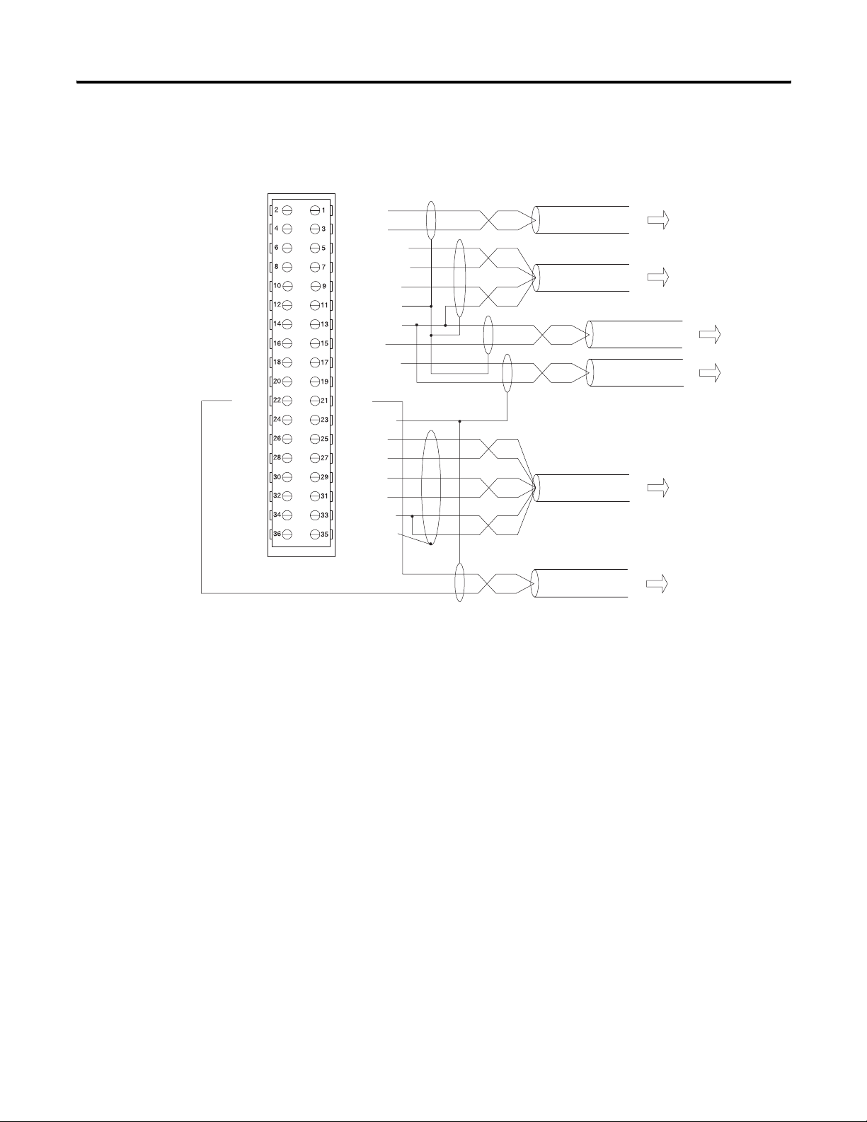
Wiring the 1756-HYD02 Module
+OUT-0
-OUT-0
+ENABLE-0
-ENABLE-0
DRVFLT-0
CHASSIS
IN_COM
HOME-0
REG24V-0
REG5V-0
CHASSIS
+INT-0
-INT-0
+RET-0
-RET-0
LDT CMN
CHASSIS
+OK
Use the wiring example in Figure to wire to your module.
+OUT-1
-OUT-1
+ENABLE-1
-ENABLE-1
DRVFLT-1
CHASSIS
IN_COM
HOME-1
REG24V-1
REG5V-1
-OK
CHASSIS
+INT-1
-INT-1
+RET-1
-RET-1
LDT CMN
CHASSIS
General cable C0720
General cable C0721
General cable C0720
General cable C0720
General cable C0722
To valve driver/amplifier
To hydraulic control unit
or
To valve or pump
To home
limit switch
To registration
sensor
To LDT
NOTES:
General cable C0720
1. This is a general wiring example illustrating Axis 1 wiring only. Other
configurations are possible with Axis wiring identical to Axis 1.
2. Make sure that any transducer connected to the 1756-HYD02 module
uses an external interrogation signal.
3. Do not exceed the specified isolation voltage between power sources.
To E-stop relay coil
43394
18 Publication 1756-UM525A-EN-P - June 2003
From 1756-HYD02
Installing the 1756-HYD02 Module Chapter 2
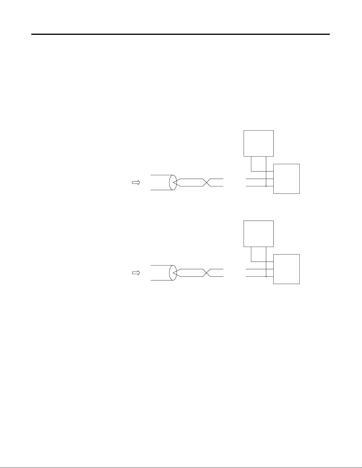
Wiring Registration Sensors
The registration inputs to the servo module can support 24V or 5V
registration sensors. These inputs should be wired to receive source current
from the sensor. Current sinking sensor configurations are not allowed
because the registration input common (IN_ COM) is shared with the other
24V servo module inputs.
- 24V Registration Sensor
24V dc
Field Power
General cable
C0720
REG24V
IN_COM
Supply
+
–
24 Volt
Registration
Sensor
Supply
Output
Common
43395
From 1756-HYD02
- 5V Registration Sensor
General cable
C0720
REG5V
IN_COM
5V dc
Field Power
Supply
+
–
5 Volt
Registration
Sensor
Supply
Output
Common
43395
Publication 1756-UM525A-EN-P - June 2003 19
Chapter 2 Installing the 1756-HYD02 Module
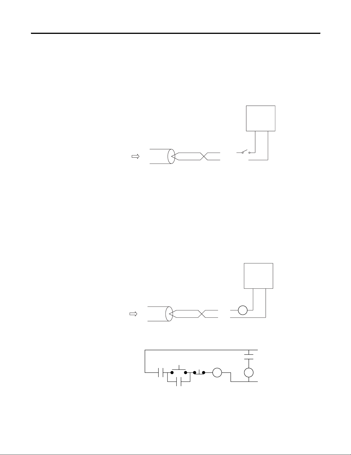
Wiring the Home Limit Switch Input
The home limit switch inputs to the servo module are designed for 24V
nominal operation. These inputs should be wired for current sourcing
operation.
24V dc
Field Power
Supply
+–
From 1756-HYD02
From 1756-HYD02
General cable
C0720
HOME
IN_COM
43396
Wiring the OK Contacts
A set of isolated solid- state OK relay contacts is provided for optional
interface to an E- stop string, which controls power to the associated pumps.
The OK contacts are rated to drive an external 24V pilot relay, for example,
Allen-Bradley 700-HA32Z24, whose contacts can be incorporated into the
E-Stop string.
24V dc
Field Power
Supply
+–
OK Pilot
Relay
General cable
C0720
+OK
-OK
43397
OK Pilot
Relay
Contacts
20 Publication 1756-UM525A-EN-P - June 2003
Start
CR1
Stop
CR1
CR1
M1
24V AC/DC
or 120VAC
typical
43398
Installing the 1756-HYD02 Module Chapter 2
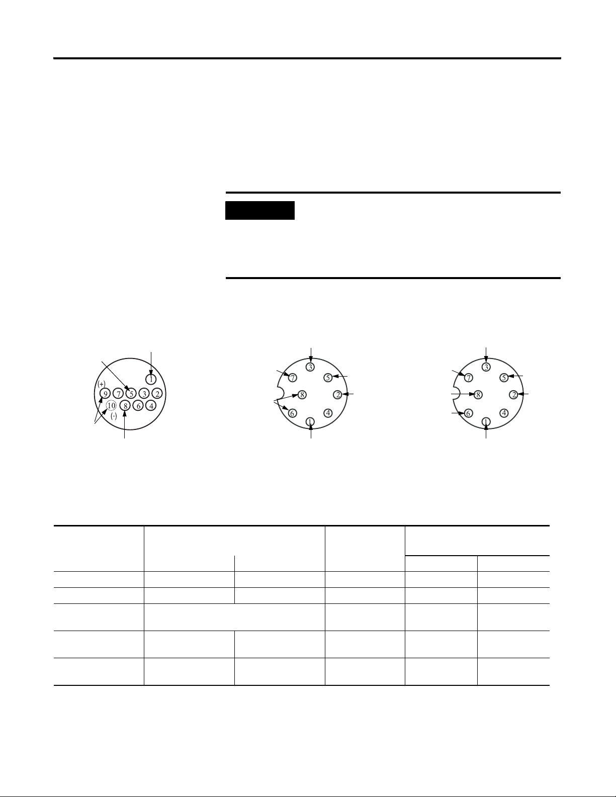
Connecting LDTs to Your Hydraulic Module
Because the number of LDTs that you can connect to your 1756-HYD02
module is continually changing, we cannot list all the available LDTs here.
Figure shows the connections for two example LDT types–Temposonic and
Balluff–that were available for connection to the 1756-HYD02 module at the
time of this printing.
+/-12V dc
Interrogate
Temposonics II,
RPM or DPM
Ground
Output Pulse
IMPORTANT
Remember, there are other suppliers with compatible LDTs.
Before connecting an LDT to your module, we recommend you
make sure it is the best available LDT for your application.
Also, when wiring an LDT to your module, always follow the
LDT manufacturer’s instructions on making connections.
24V Connections +/- 15V Connections
Interrogate (-)
+24V
Ground
Interrogate (+)
No shield connections on these examples
Pulse (-)
Output
Pulse (+)
Output
Table lists the LDT connections.
Balluff BTL type
+15V
-15V
Ground
Interrogate (-)
Interrogate (+)
Pulse (-)
Output
Pulse (+)
Output
43473
LDT Connections for Fabricating Your Own LDT Cable
Function
(1)
1756-HYD02 RTB Wiring (Numbers below
represent terminal numbers)
Temposonics II
RPM or DPM
(2)
Balluff
BTL type
Channel 0 Channel 1 24V dc +/- 15V dc
(+) Interrogate 26 25 9 - Yellow 1 - Yellow 1 - Yellow
(-) Interrogate 28 27 10 - Green 3 - Pink 3 - Pink
Power Supply N/A 5 - Red (+/-12V) 7 - Brown (+24V) 7 - Brown (+15V)
8 - White (-15V)
Ground 34 33 1 - White 6 - Blue
6 - Blue
8 - White
Output Pulse 30 (+)
32 (-)
(1)
(+) and (-) wires of the same function should be a twisted pair within the cable.
(2)
Do not connect to pins 2, 3, 4, 6 or 7
Publication 1756-UM525A-EN-P - June 2003 21
29 (+)
31 (-)
8 - Purple 2 - Gray (+)
5 - Green (-)
2 - Gray (+)
5 - Green (-)
Chapter 2 Installing the 1756-HYD02 Module
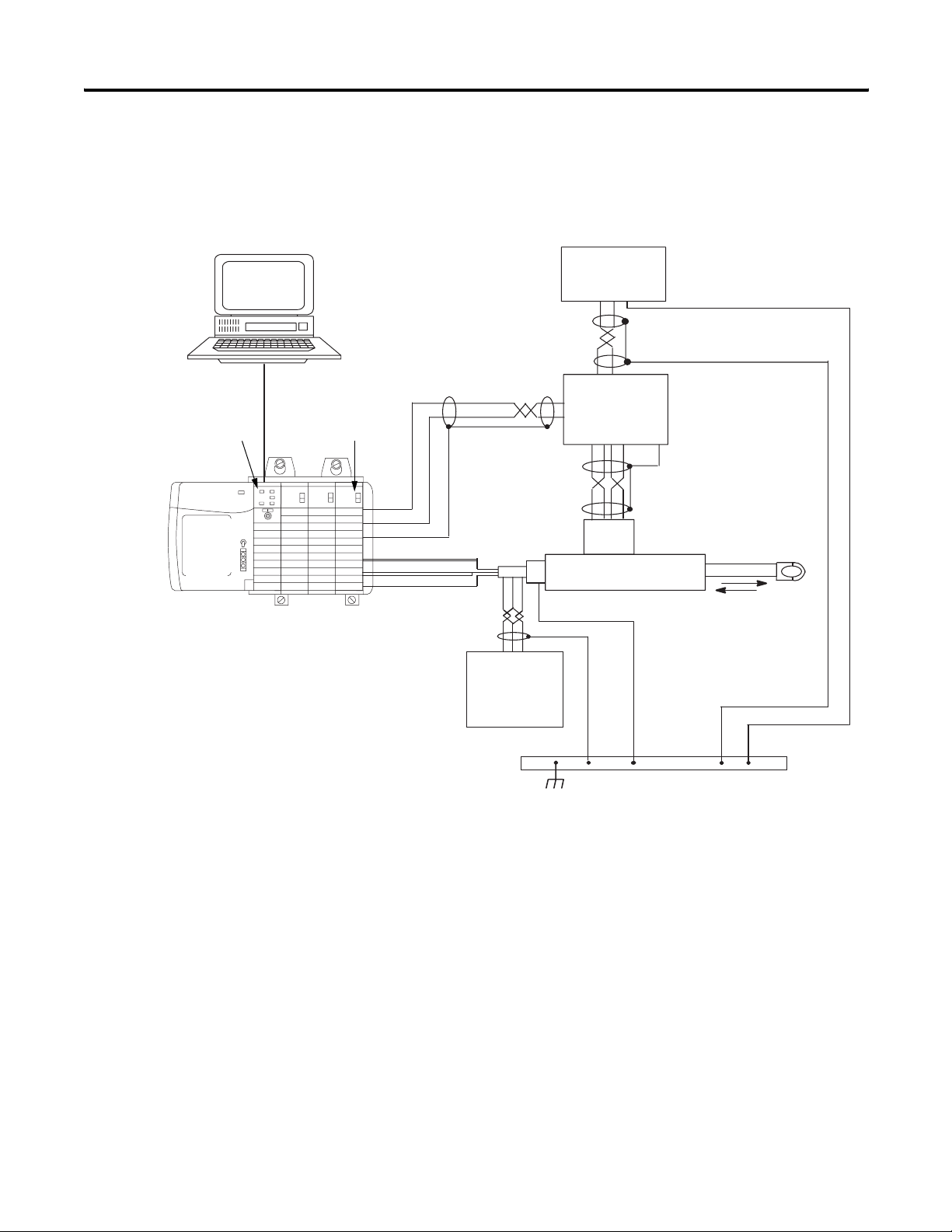
PC with
RSLogix 5000™
Figure shows an application wiring example using a 1-axis loop with a
differential LDT input. (The power supplies and servo amplifiers are
user-supplied.)
24V Power Supply
+–C
ControlLogix
controller
1756-HYD02
+ OUT
– OUT
CHASSIS
+INT & –INT
+RET & –RET
CHASSIS
Drive Output
+–C
+/– 15V dc
Power Supply
for LDTs
Servo or
Proportional
Amplifier
Valve
Piston-type Hydraulic
Cylinder and LDT
Earth Ground
IMPORTANT: This
module’s analog
output require an
external amplifier to
drive the valve.
43474
22 Publication 1756-UM525A-EN-P - June 2003
Installing the 1756-HYD02 Module Chapter 2
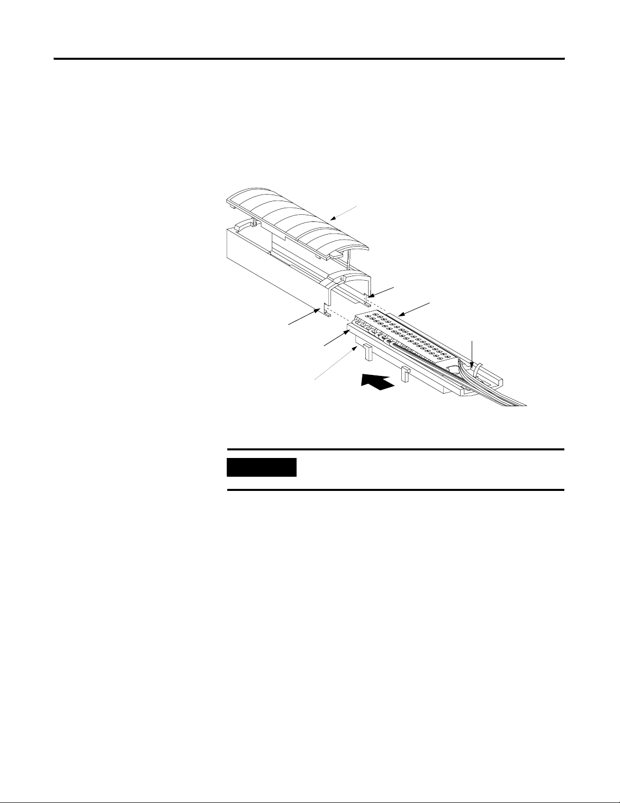
Assembling The Removable
Removable housing covers the wired RTB to protect wiring connections when
the RTB is seated on the module.
Terminal Block and the
Housing
1. Align the grooves at the bottom of each side of the housing with the
side edges of the RTB.
Housing
Groove
Side edge of RTB
Groove
Strain relief area
Side edge of RTB
RTB
2. Slide the RTB into the housing until it snaps into place.
IMPORTANT
If additional wire routing space is required for your application,
use extended-depth housing 1756-TBE.
20858-M
Publication 1756-UM525A-EN-P - June 2003 23
Chapter 2 Installing the 1756-HYD02 Module
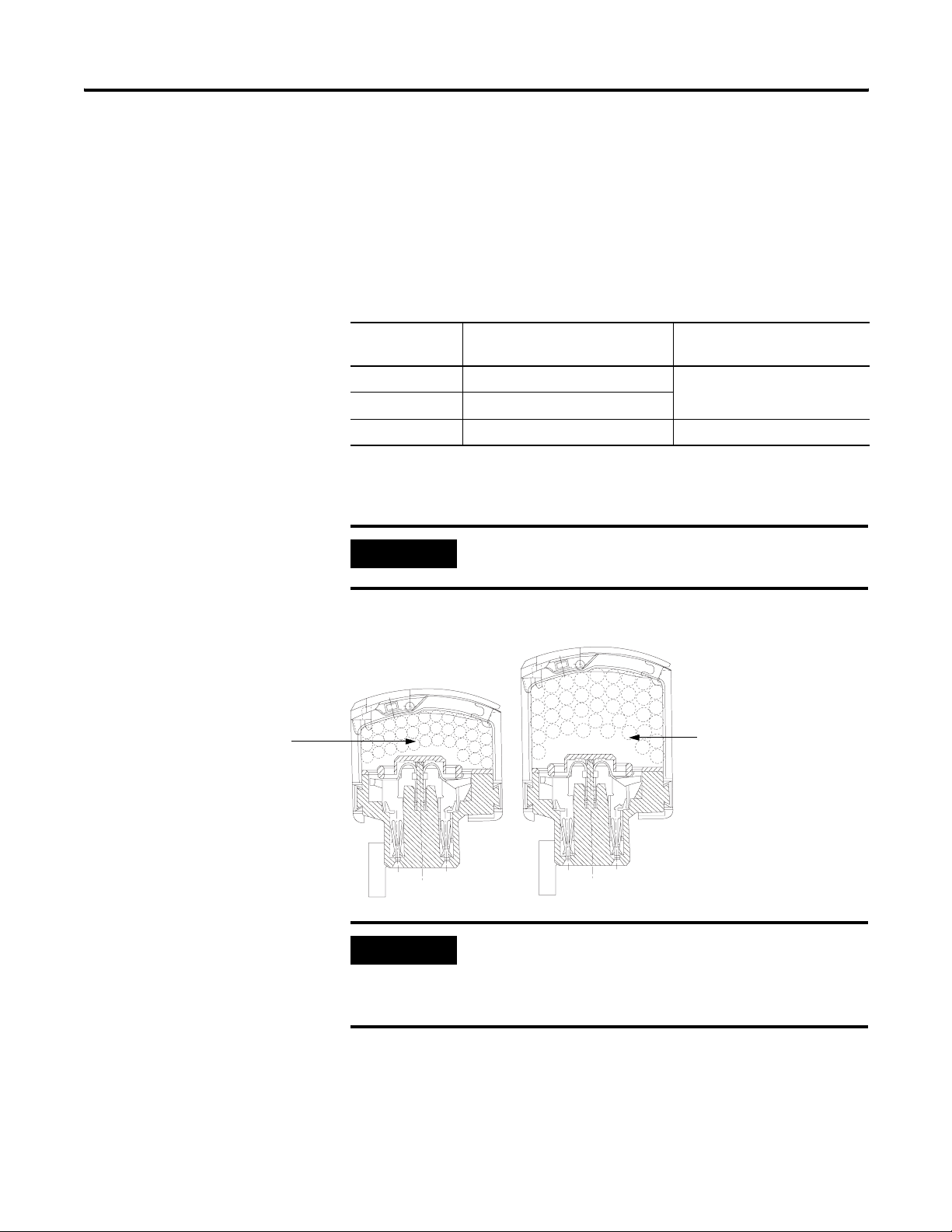
Choosing the Extended-Depth Housing
There are two housing options you must consider when wiring your
ControlLogix Hydraulic Servo module. When you order an RTB for your I/O
module, you receive a standard-depth housing with the RTB. If your
application uses heavy gauge wiring, you can order an extended-depth housing.
This housing does not come with an RTB.
You can use one of the housings listed below:
This housing: should be used with this RTB: and allows up to this
capacity of wires:
1756-TBCH Cage clamp 336 sq. mm
1756-TBS6H Spring clamp
1756-TBE Any RTB using heavy gauge wiring 628 sq. mm
The figure below shows the difference, in terms of capacity, between the
housing options.
IMPORTANT
The housings shown are used with a spring clamp RTB, but the
capacity for each remains the same regardless of RTB type.
Maximum Area = 336 sq. mm
36 - 18AWG wires
23 - 14AWG wires
Standard-Depth Housing Extended-Depth Housing
IMPORTANT
The housings use the following maximum areas:
• standard-depth housing maximum area = 336 sq. mm
• extended-depth housing maximum area = 628 sq. mm
Maximum Area = 628 sq. mm
40 - 14AWG wires
30484-M
24 Publication 1756-UM525A-EN-P - June 2003
Installing the 1756-HYD02 Module Chapter 2
Suggestions for Using the Extended-Depth Housing
12.7mm
(0.5in)
TIP
Consider the following when deciding to use an extended-depth
housing on your I/O module. It is recommended you use the 1756-TBE
when:
• using >36 18AWG wires
• using >23 14AWG wires
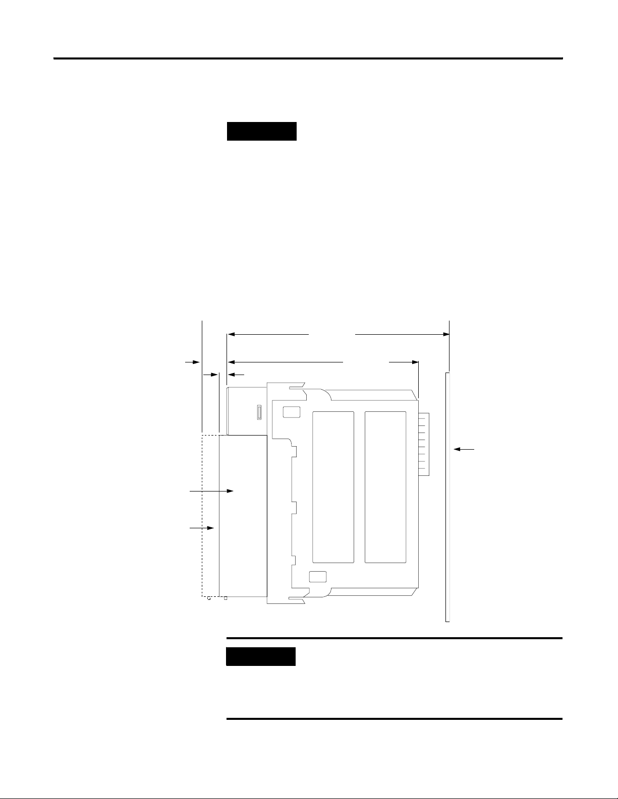
Cabinet Size Considerations With the Extended-Depth Housing
When you use an extended-depth housing (1756-TBE), the module depth is
increased. Figure shows the difference, in terms of depth, between a module
using a standard-depth housing and one using an extended-depth housing.
144.73mm
(5.698in)
131.75mm
3.18mm (0.125in)
(5.187in)
Standard-Depth Housing
Extended-Depth Housing
IMPORTANT
Rear Surface of
ControlLogix Chassis
41682
The depth from front of the module to the back of the chassis is
as follows:
• standard-depth housing = 147.91mm (5.823in)
• extended-depth housing = 157.43mm (6.198in)
Publication 1756-UM525A-EN-P - June 2003 25
Chapter 2 Installing the 1756-HYD02 Module
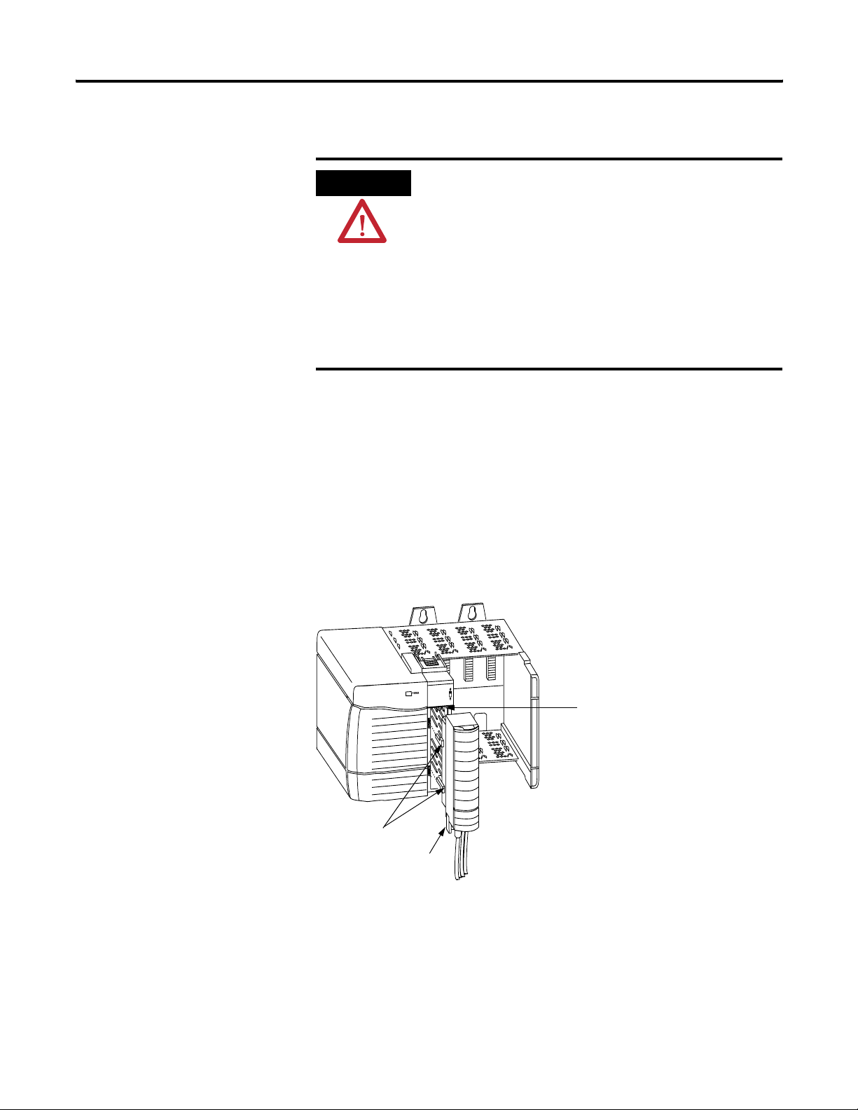
Installing the Removable Terminal Block
Install the RTB onto the module to connect wiring.
ATTENTION
Shock hazard exists. If the RTB is installed onto the module
while the field-side power is applied, the RTB will be
electrically live. Do not touch the RTB’s terminals. Failure to
observe this caution may cause personal injury.
The RTB is designed to support Removal and Insertion Under
Power (RIUP). However, when you remove or insert an RTB with
field-side power applied, unintended machine motion or
loss of process control can occur. Exercise extreme caution
when using this feature. It is recommended that field-side
power be removed before installing the RTB onto the module.
Before installing the RTB, make certain:
• field-side wiring of the RTB has been completed.
• the RTB housing is snapped into place on the RTB.
• the RTB housing door is closed.
• the locking tab at the top of the module is unlocked.
1. Align the top, bottom and left side guides of the RTB with the guides on
the module.
Left side guides
Bottom guide
Top guide
20853-M
26 Publication 1756-UM525A-EN-P - June 2003
Installing the 1756-HYD02 Module Chapter 2
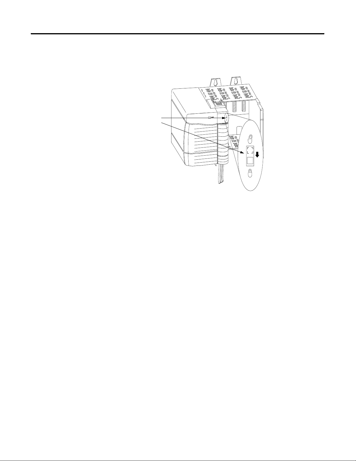
2. Press quickly and evenly to seat the RTB on the module until the latches
snap into place.
Locking tab
20854-M
3. Slide the locking tab down to lock the RTB onto the module.
Publication 1756-UM525A-EN-P - June 2003 27
Chapter 2 Installing the 1756-HYD02 Module
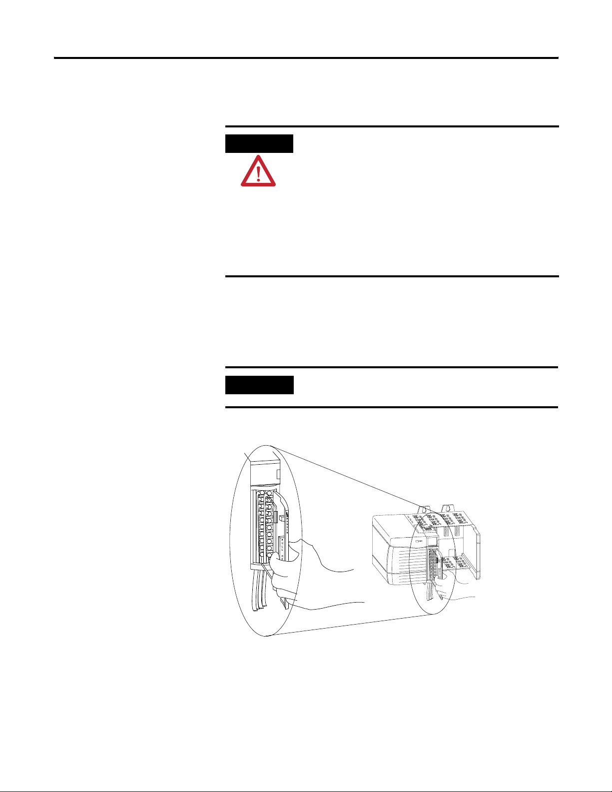
Removing the Removable Terminal Block
If you need to remove the module from the chassis, you must first remove the
RTB from the module.
ATTENTION
Shock hazard exists. If the RTB is removed from the module
while the field-side power is applied, the module will be
electrically live. Do not touch the RTB’s terminals. Failure to
observe this caution may cause personal injury.
The RTB is designed to support Removal and Insertion Under
Power (RIUP). However, when you remove or insert an RTB with
field-side power applied, unintended machine motion or
loss of process control can occur. Exercise extreme caution
when using this feature. It is recommended that field-side
power be removed before removing the module.
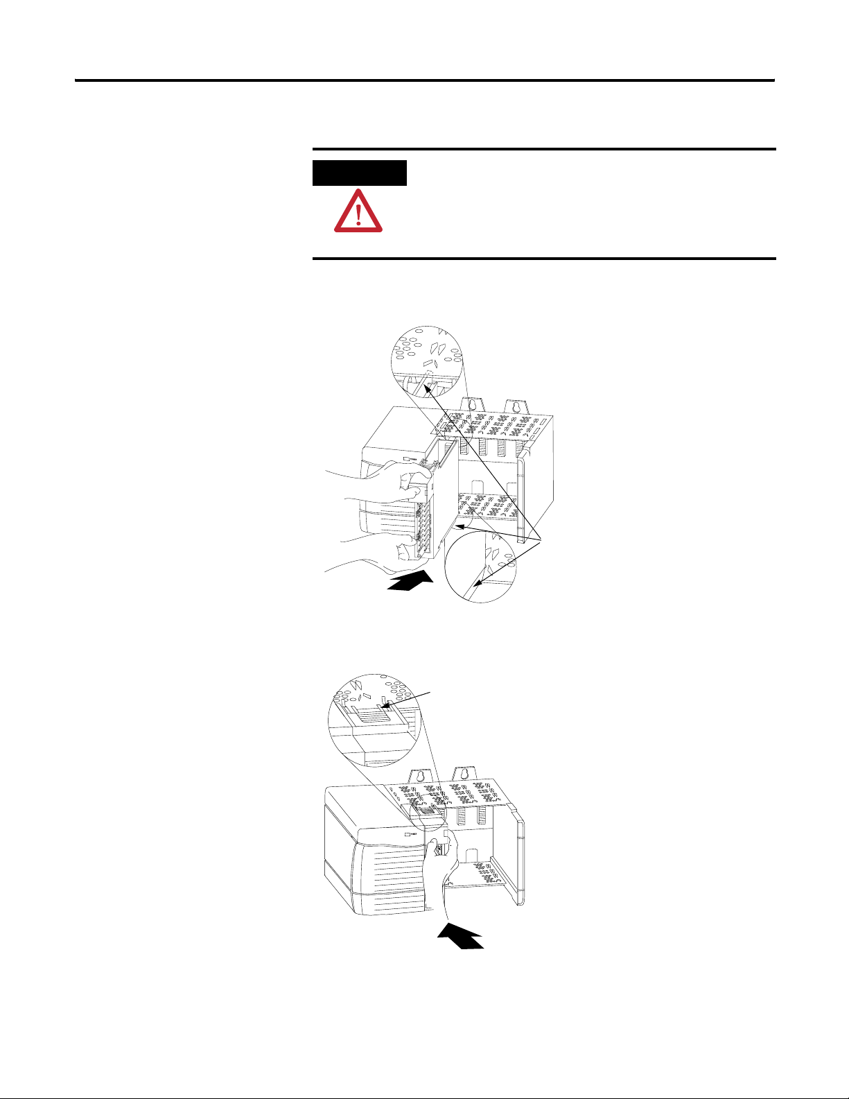
1. Unlock the locking tab at the top of the module.
2. Open the RTB door using the bottom tab.
3. Hold the spot marked PULL HERE and pull the RTB off the module.
IMPORTANT
Do not wrap your fingers around the entire door. A shock hazard
exists.
20855-M
28 Publication 1756-UM525A-EN-P - June 2003
Installing the 1756-HYD02 Module Chapter 2
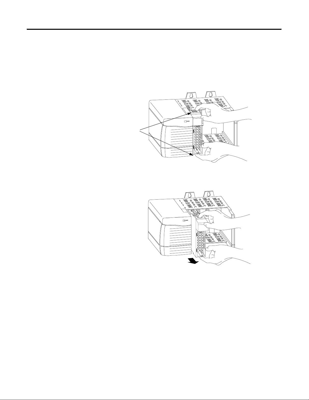
Removing the Module from the Chassis
Follow the steps below to remove the 1756-HYD02 module from the
ControlLogix chassis.
1. Push in the top and bottom locking tabs.
Locking tabs
20856-M
2. Pull module out of the chassis.
20857-M
Publication 1756-UM525A-EN-P - June 2003 29

Chapter 2 Installing the 1756-HYD02 Module
Chapter Summary and What’s Next
In this chapter, you read about Installing the 1756-HYD02 Module. Chapter 3
explains Configuring the 1756-HYD02 Module.
30 Publication 1756-UM525A-EN-P - June 2003
Loading...