


1756-OF8I
Table of contents
 Loading...
User Manual
ControlLogix Eight-channel Isolated Analog I/O Modules
Catalog Numbers 1756-IF8I, 1756-IRT8I, 1756-OF8I
Important User Information
IMPORTANT
Read this document and the documents listed in the additional resources section about installation, configuration, and
operation of this equipment before you install, configure, operate, or maintain this product. Users are required to
familiarize themselves with installation and wiring instructions in addition to requirements of all applicable codes, laws,
and standards.
Activities including installation, adjustments, putting into service, use, assembly, disassembly, and maintenance are required
to be carried out by suitably trained personnel in accordance with applicable code of practice.
If this equipment is used in a manner not specified by the manufacturer, the protection provided by the equipment may be
impaired.
In no event will Rockwell Automation, Inc. be responsible or liable for indirect or consequential damages resulting from the
use or application of this equipment.
The examples and diagrams in this manual are included solely for illustrative purposes. Because of the many variables and
requirements associated with any particular installation, Rockwell Automation, Inc. cannot assume responsibility or
liability for actual use based on the examples and diagrams.
No patent liability is assumed by Rockwell Automation, Inc. with respect to use of information, circuits, equipment, or
software described in this manual.
Reproduction of the contents of this manual, in whole or in part, without written permission of Rockwell Automation,
Inc., is prohibited.
Throughout this manual, when necessary, we use notes to make you aware of safety considerations.
WARNING: Identifies information about practices or circumstances that can cause an explosion in a hazardous environment,
which may lead to personal injury or death, property damage, or economic loss.
ATTENTION: Identifies information about practices or circumstances that can lead to personal injury or death, property
damage, or economic loss. Attentions help you identify a hazard, avoid a hazard, and recognize the consequence.
Identifies information that is critical for successful application and understanding of the product.
Labels may also be on or inside the equipment to provide specific precautions.
SHOCK HAZARD: Labels may be on or inside the equipment, for example, a drive or motor, to alert people that dangerous
voltage may be present.
BURN HAZARD: Labels may be on or inside the equipment, for example, a drive or motor, to alert people that surfaces may
reach dangerous temperatures.
ARC FLASH HAZARD: Labels may be on or inside the equipment, for example, a motor control center, to alert people to
potential Arc Flash. Arc Flash will cause severe injury or death. Wear proper Personal Protective Equipment (PPE). Follow ALL
Regulatory requirements for safe work practices and for Personal Protective Equipment (PPE).
Allen-Bradley, ControlLogix, Integrated Architecture, Logix Designer, Logix5000, Rockwell Software, Rockwell Automation, RSLogix, Studio 5000, an d Studio 5000 Log ix Designer are trademarks of Rockwell Automation,
Inc.
Trademarks not belonging to Rockwell Automation are property of their respective companies.

Table of Contents
Preface
Isolated Analog I/O Module
Operation in the
ControlLogix System
ControlLogix Isolated Analog I/O
Module Features
Studio 5000 Environment . . . . . . . . . . . . . . . . . . . . . . . . . . . . . . . . . . . . . . . . . . 7
Additional Resources . . . . . . . . . . . . . . . . . . . . . . . . . . . . . . . . . . . . . . . . . . . . . . . 8
Chapter 1
Before You Begin . . . . . . . . . . . . . . . . . . . . . . . . . . . . . . . . . . . . . . . . . . . . . . . . . . 9
Ownership . . . . . . . . . . . . . . . . . . . . . . . . . . . . . . . . . . . . . . . . . . . . . . . . . . . . . . 11
Configure a Module . . . . . . . . . . . . . . . . . . . . . . . . . . . . . . . . . . . . . . . . . . . . . . 11
Direct Connections . . . . . . . . . . . . . . . . . . . . . . . . . . . . . . . . . . . . . . . . . . . . . . 12
Input Module Operation . . . . . . . . . . . . . . . . . . . . . . . . . . . . . . . . . . . . . . . . . 14
Requested Packet Interval (RPI) . . . . . . . . . . . . . . . . . . . . . . . . . . . . . . . 14
Input Modules in a Local Chassis . . . . . . . . . . . . . . . . . . . . . . . . . . . . . . 15
Input Modules in a Remote Chassis. . . . . . . . . . . . . . . . . . . . . . . . . . . . 15
Triggering Event Tasks . . . . . . . . . . . . . . . . . . . . . . . . . . . . . . . . . . . . . . . 16
Output Module Operation . . . . . . . . . . . . . . . . . . . . . . . . . . . . . . . . . . . . . . . 17
Output Modules in a Local Chassis . . . . . . . . . . . . . . . . . . . . . . . . . . . . 17
Output Modules in a Remote Chassis . . . . . . . . . . . . . . . . . . . . . . . . . . 17
Listen-only Mode . . . . . . . . . . . . . . . . . . . . . . . . . . . . . . . . . . . . . . . . . . . . . . . . 18
Chapter 2
Common Analog I/O Features. . . . . . . . . . . . . . . . . . . . . . . . . . . . . . . . . . . . 20
CIP Sync Timestamp of Data . . . . . . . . . . . . . . . . . . . . . . . . . . . . . . . . . 20
Rolling Timestamp of Data . . . . . . . . . . . . . . . . . . . . . . . . . . . . . . . . . . . 21
Floating Point Data Format . . . . . . . . . . . . . . . . . . . . . . . . . . . . . . . . . . . 22
Module Resolution . . . . . . . . . . . . . . . . . . . . . . . . . . . . . . . . . . . . . . . . . . . 22
Module Quality Reporting . . . . . . . . . . . . . . . . . . . . . . . . . . . . . . . . . . . . 23
Calibration . . . . . . . . . . . . . . . . . . . . . . . . . . . . . . . . . . . . . . . . . . . . . . . . . . 24
Fault and Status Reporting . . . . . . . . . . . . . . . . . . . . . . . . . . . . . . . . . . . . 24
Configurable Software . . . . . . . . . . . . . . . . . . . . . . . . . . . . . . . . . . . . . . . . 25
Latching of Alarms . . . . . . . . . . . . . . . . . . . . . . . . . . . . . . . . . . . . . . . . . . . 26
Module Inhibiting. . . . . . . . . . . . . . . . . . . . . . . . . . . . . . . . . . . . . . . . . . . . 26
Electronic Keying . . . . . . . . . . . . . . . . . . . . . . . . . . . . . . . . . . . . . . . . . . . . 28
Exact Match . . . . . . . . . . . . . . . . . . . . . . . . . . . . . . . . . . . . . . . . . . . . . . . . . 30
Compatible Keying . . . . . . . . . . . . . . . . . . . . . . . . . . . . . . . . . . . . . . . . . . . 31
Disabled Keying. . . . . . . . . . . . . . . . . . . . . . . . . . . . . . . . . . . . . . . . . . . . . . 33
Relationship between Module Resolution and Scaling. . . . . . . . . . . . . . . 35
Module Resolution . . . . . . . . . . . . . . . . . . . . . . . . . . . . . . . . . . . . . . . . . . . 35
Scaling. . . . . . . . . . . . . . . . . . . . . . . . . . . . . . . . . . . . . . . . . . . . . . . . . . . . . . . 37
Calibration . . . . . . . . . . . . . . . . . . . . . . . . . . . . . . . . . . . . . . . . . . . . . . . . . . . . . . 38
Calibrated Accuracy. . . . . . . . . . . . . . . . . . . . . . . . . . . . . . . . . . . . . . . . . . . . . . 38
Calibrated Accuracy at 25 °C (77 °F). . . . . . . . . . . . . . . . . . . . . . . . . . . 38
Module Error over Full Temperature Range . . . . . . . . . . . . . . . . . . . . 39
Error Calculated over Hardware Range . . . . . . . . . . . . . . . . . . . . . . . . . . . . 39
Rockwell Automation Publication 1756-UM540A-EN-P - May 2014 3

Table of Contents
RTD and Thermocouple Error Calculations. . . . . . . . . . . . . . . . . . . . . . . . 39
RTD Error. . . . . . . . . . . . . . . . . . . . . . . . . . . . . . . . . . . . . . . . . . . . . . . . . . . 40
Thermocouple Error . . . . . . . . . . . . . . . . . . . . . . . . . . . . . . . . . . . . . . . . . . 41
Module Error at 25 °C (77 °F) . . . . . . . . . . . . . . . . . . . . . . . . . . . . . . . . . 42
Thermocouple Resolution . . . . . . . . . . . . . . . . . . . . . . . . . . . . . . . . . . . . . . . . 43
Chapter 3
1756-IF8I Isolated Analog
Input Module
1756-IRT8I Combined
Temperature-sensing
Isolated Analog Module
1756-IF8I Module Features . . . . . . . . . . . . . . . . . . . . . . . . . . . . . . . . . . . . . . . 45
Internal Loop Power Source . . . . . . . . . . . . . . . . . . . . . . . . . . . . . . . . . . . 46
Multiple Input Ranges . . . . . . . . . . . . . . . . . . . . . . . . . . . . . . . . . . . . . . . . 47
Notch Filter. . . . . . . . . . . . . . . . . . . . . . . . . . . . . . . . . . . . . . . . . . . . . . . . . . 48
Underrange/Overrange Detection . . . . . . . . . . . . . . . . . . . . . . . . . . . . . 51
Digital Filter . . . . . . . . . . . . . . . . . . . . . . . . . . . . . . . . . . . . . . . . . . . . . . . . . 52
Process Alarms . . . . . . . . . . . . . . . . . . . . . . . . . . . . . . . . . . . . . . . . . . . . . . . 53
Rate Alarm. . . . . . . . . . . . . . . . . . . . . . . . . . . . . . . . . . . . . . . . . . . . . . . . . . . 55
Sensor Offset. . . . . . . . . . . . . . . . . . . . . . . . . . . . . . . . . . . . . . . . . . . . . . . . . 55
Wire Off Detection. . . . . . . . . . . . . . . . . . . . . . . . . . . . . . . . . . . . . . . . . . . 56
Synchronized Sampling . . . . . . . . . . . . . . . . . . . . . . . . . . . . . . . . . . . . . . . 57
Module Block and Circuit Diagrams . . . . . . . . . . . . . . . . . . . . . . . . . . . . . . . 58
Field-side Circuit Diagrams. . . . . . . . . . . . . . . . . . . . . . . . . . . . . . . . . . . . 59
Wire the 1756-IF8I Module. . . . . . . . . . . . . . . . . . . . . . . . . . . . . . . . . . . . . . . 61
Fault and Status Reporting . . . . . . . . . . . . . . . . . . . . . . . . . . . . . . . . . . . . . . . . 64
Chapter 4
1756-IRT8I Module Features . . . . . . . . . . . . . . . . . . . . . . . . . . . . . . . . . . . . . 65
Multiple Input Ranges . . . . . . . . . . . . . . . . . . . . . . . . . . . . . . . . . . . . . . . . 66
Notch Filter. . . . . . . . . . . . . . . . . . . . . . . . . . . . . . . . . . . . . . . . . . . . . . . . . . 67
Underrange/Overrange Detection . . . . . . . . . . . . . . . . . . . . . . . . . . . . . 70
Digital Filter . . . . . . . . . . . . . . . . . . . . . . . . . . . . . . . . . . . . . . . . . . . . . . . . . 71
Process Alarms . . . . . . . . . . . . . . . . . . . . . . . . . . . . . . . . . . . . . . . . . . . . . . . 72
Rate Alarm. . . . . . . . . . . . . . . . . . . . . . . . . . . . . . . . . . . . . . . . . . . . . . . . . . . 74
Sensor Offset. . . . . . . . . . . . . . . . . . . . . . . . . . . . . . . . . . . . . . . . . . . . . . . . . 74
10 Ohm Copper Offset . . . . . . . . . . . . . . . . . . . . . . . . . . . . . . . . . . . . . . . 75
Wire Off Detection. . . . . . . . . . . . . . . . . . . . . . . . . . . . . . . . . . . . . . . . . . . 75
Temperature Units . . . . . . . . . . . . . . . . . . . . . . . . . . . . . . . . . . . . . . . . . . . 77
Sensor Types . . . . . . . . . . . . . . . . . . . . . . . . . . . . . . . . . . . . . . . . . . . . . . . . . 77
Thermocouple Wire Length Compensation . . . . . . . . . . . . . . . . . . . . 81
Synchronized Sampling . . . . . . . . . . . . . . . . . . . . . . . . . . . . . . . . . . . . . . . 81
Cold Junction Compensation . . . . . . . . . . . . . . . . . . . . . . . . . . . . . . . . . 82
Module Block and Circuit Diagrams . . . . . . . . . . . . . . . . . . . . . . . . . . . . . . . 87
Field-side Circuit Diagrams. . . . . . . . . . . . . . . . . . . . . . . . . . . . . . . . . . . . 88
Wire the 1756-IRT8I Module. . . . . . . . . . . . . . . . . . . . . . . . . . . . . . . . . . . . . 89
Fault and Status Reporting . . . . . . . . . . . . . . . . . . . . . . . . . . . . . . . . . . . . . . . . 92
4 Rockwell Automation Publication 1756-UM540A-EN-P - May 2014

Chapter 5
Table of Contents
1756-OF8I Isolated Analog Output
Module
Install ControlLogix Isolated
Analog I/O Modules
1756-OF8I Module Features. . . . . . . . . . . . . . . . . . . . . . . . . . . . . . . . . . . . . . 93
Multiple Output Ranges . . . . . . . . . . . . . . . . . . . . . . . . . . . . . . . . . . . . . . 94
Channel Offset. . . . . . . . . . . . . . . . . . . . . . . . . . . . . . . . . . . . . . . . . . . . . . . 94
Ramping/Rate Limiting. . . . . . . . . . . . . . . . . . . . . . . . . . . . . . . . . . . . . . . 95
Hold for Initialization . . . . . . . . . . . . . . . . . . . . . . . . . . . . . . . . . . . . . . . . 95
Clamping/Limiting. . . . . . . . . . . . . . . . . . . . . . . . . . . . . . . . . . . . . . . . . . . 96
Clamp/Limit Alarms . . . . . . . . . . . . . . . . . . . . . . . . . . . . . . . . . . . . . . . . . 97
Data Echo . . . . . . . . . . . . . . . . . . . . . . . . . . . . . . . . . . . . . . . . . . . . . . . . . . . 97
Module Block and Output Circuit Diagrams . . . . . . . . . . . . . . . . . . . . . . . 98
Field-side Circuit Diagrams . . . . . . . . . . . . . . . . . . . . . . . . . . . . . . . . . . . 99
Drive Different Loads
with the 1756-OF8I Module . . . . . . . . . . . . . . . . . . . . . . . . . . . . . . . . . . . . . 100
Wire the 1756-OF8I Module . . . . . . . . . . . . . . . . . . . . . . . . . . . . . . . . . . . . 100
Fault and Status Reporting. . . . . . . . . . . . . . . . . . . . . . . . . . . . . . . . . . . . . . . 102
Chapter 6
Install the I/O Module . . . . . . . . . . . . . . . . . . . . . . . . . . . . . . . . . . . . . . . . . . 106
Key the Removable Terminal Block. . . . . . . . . . . . . . . . . . . . . . . . . . . . . . . 108
Connect Wiring . . . . . . . . . . . . . . . . . . . . . . . . . . . . . . . . . . . . . . . . . . . . . . . . 109
Connect the Grounded End of the Cable. . . . . . . . . . . . . . . . . . . . . . 110
Connect the Ungrounded End of the Cable . . . . . . . . . . . . . . . . . . . 111
RTB Types . . . . . . . . . . . . . . . . . . . . . . . . . . . . . . . . . . . . . . . . . . . . . . . . . 112
RTB Wiring Recommendations . . . . . . . . . . . . . . . . . . . . . . . . . . . . . . 113
Assemble the RTB and the Housing . . . . . . . . . . . . . . . . . . . . . . . . . . . . . . 114
Choose Extended-depth Housing . . . . . . . . . . . . . . . . . . . . . . . . . . . . . . . . 115
Cabinet Size Considerations with Extended-depth Housing . . . . 116
Install the Removable Terminal Block . . . . . . . . . . . . . . . . . . . . . . . . . . . . 117
Remove the Removable Terminal Block. . . . . . . . . . . . . . . . . . . . . . . . . . . 118
Remove the Module from the Chassis. . . . . . . . . . . . . . . . . . . . . . . . . . . . . 119
Configure ControlLogix Isolated
AnalogI/O Modules
Chapter 7
Create a New Module . . . . . . . . . . . . . . . . . . . . . . . . . . . . . . . . . . . . . . . . . . . 122
Module Definition . . . . . . . . . . . . . . . . . . . . . . . . . . . . . . . . . . . . . . . . . . 124
Edit the Configuration . . . . . . . . . . . . . . . . . . . . . . . . . . . . . . . . . . . . . . . . . . 125
Connection Tab . . . . . . . . . . . . . . . . . . . . . . . . . . . . . . . . . . . . . . . . . . . . 126
Configuration Tab . . . . . . . . . . . . . . . . . . . . . . . . . . . . . . . . . . . . . . . . . . 127
Calibration Tab . . . . . . . . . . . . . . . . . . . . . . . . . . . . . . . . . . . . . . . . . . . . . 129
Alarm Configuration Tab. . . . . . . . . . . . . . . . . . . . . . . . . . . . . . . . . . . . 131
CJ Configuration Tab . . . . . . . . . . . . . . . . . . . . . . . . . . . . . . . . . . . . . . . 132
Limit Configuration Tab . . . . . . . . . . . . . . . . . . . . . . . . . . . . . . . . . . . . 133
Copy Channel Configuration . . . . . . . . . . . . . . . . . . . . . . . . . . . . . . . . . . . . 134
View the Module Tags. . . . . . . . . . . . . . . . . . . . . . . . . . . . . . . . . . . . . . . . . . . 136
Rockwell Automation Publication 1756-UM540A-EN-P - May 2014 5

Table of Contents
Chapter 8
Calibrate the ControlLogix Isolated
Analog I/O Modules
Troubleshoot Your Module
Difference between Calibrating an Input Module and
an Output Module . . . . . . . . . . . . . . . . . . . . . . . . . . . . . . . . . . . . . . . . . . . . . . 138
Calibrate in Program Mode. . . . . . . . . . . . . . . . . . . . . . . . . . . . . . . . . . . 139
Calibrate the Input Modules . . . . . . . . . . . . . . . . . . . . . . . . . . . . . . . . . . . . . 139
Calibrate the 1756-IF8I Module . . . . . . . . . . . . . . . . . . . . . . . . . . . . . . 139
Calibrate the 1756-IRT8I Module . . . . . . . . . . . . . . . . . . . . . . . . . . . . 144
Calibrate the Output Module . . . . . . . . . . . . . . . . . . . . . . . . . . . . . . . . . . . . 152
Calibrate the 1756-OF8I Module for a Current Output Type . . . 152
Chapter 9
Status Indicators for the 1756-IF8I Module . . . . . . . . . . . . . . . . . . . . . . . 157
Status Indicators for the 1756-IRT8I Module. . . . . . . . . . . . . . . . . . . . . . 158
Status Indicators for the 1756-OF8I Module . . . . . . . . . . . . . . . . . . . . . . 159
Use Logix Designer Application for Troubleshooting. . . . . . . . . . . . . . . 160
Troubleshoot Incorrect Readings on the Module. . . . . . . . . . . . . . . . . . . 162
1756-IRT8I Module - Incorrect Temperature Readings. . . . . . . . . 162
1756-IRT8I Module - Incorrect RTD Readings . . . . . . . . . . . . . . . . 165
1756-IF8I Module - Incorrect Input Voltage/Current Readings . 168
1756-OF8I Module - Incorrect Output Voltage/Current
Readings . . . . . . . . . . . . . . . . . . . . . . . . . . . . . . . . . . . . . . . . . . . . . . . . . . . . 171
Isolated Analog I/O Module Tag
Definitions
Choose the Correct Power Supply
1492 Analog Interface Modules
Appendix A
Access the Tags. . . . . . . . . . . . . . . . . . . . . . . . . . . . . . . . . . . . . . . . . . . . . . . . . . 173
1756-IF8I Module Tags. . . . . . . . . . . . . . . . . . . . . . . . . . . . . . . . . . . . . . . . . . 175
Configuration Tags . . . . . . . . . . . . . . . . . . . . . . . . . . . . . . . . . . . . . . . . . . 175
Input Tags . . . . . . . . . . . . . . . . . . . . . . . . . . . . . . . . . . . . . . . . . . . . . . . . . . 177
Output Tags . . . . . . . . . . . . . . . . . . . . . . . . . . . . . . . . . . . . . . . . . . . . . . . . 180
1756-IRT8I Module Tags. . . . . . . . . . . . . . . . . . . . . . . . . . . . . . . . . . . . . . . . 182
Configuration Tags . . . . . . . . . . . . . . . . . . . . . . . . . . . . . . . . . . . . . . . . . . 182
Input Tags . . . . . . . . . . . . . . . . . . . . . . . . . . . . . . . . . . . . . . . . . . . . . . . . . . 186
Output Tags . . . . . . . . . . . . . . . . . . . . . . . . . . . . . . . . . . . . . . . . . . . . . . . . 189
1756-OF8I Module Tags. . . . . . . . . . . . . . . . . . . . . . . . . . . . . . . . . . . . . . . . . 191
Configuration Tags . . . . . . . . . . . . . . . . . . . . . . . . . . . . . . . . . . . . . . . . . . 191
Input Tags . . . . . . . . . . . . . . . . . . . . . . . . . . . . . . . . . . . . . . . . . . . . . . . . . . 194
Output Tags . . . . . . . . . . . . . . . . . . . . . . . . . . . . . . . . . . . . . . . . . . . . . . . . 196
Appendix B
Power-sizing Chart . . . . . . . . . . . . . . . . . . . . . . . . . . . . . . . . . . . . . . . . . . . . . . 199
Appendix C
. . . . . . . . . . . . . . . . . . . . . . . . . . . . . . . . . . . . . . . . . . . . . . . . . . . . . . . . . . . . . . . . 201
Index
6 Rockwell Automation Publication 1756-UM540A-EN-P - May 2014
. . . . . . . . . . . . . . . . . . . . . . . . . . . . . . . . . . . . . . . . . . . . . . . . . . . . . . . . . . . . . . . . 203

Preface
This manual describes how to install, configure, and troubleshoot your
ControlLogix® isolated analog I/O module.
You must be able to program and operate a ControlLogix controller to efficiently
use your isolated analog I/O modules. If you need additional information, refer
to Additional Resources on page 8
ControlLogix isolated analog I/O modules convert analog signals to digital
values for inputs and convert digital values to analog signals for outputs.
Controllers use these signals for control purposes.
By using the producer/consumer network model, ControlLogix isolated analog
I/O modules produce information when needed while providing additional
system functions.
.
Studio 5000 Environment
The Studio 5000® Engineering and Design Environment combines engineering
and design elements into a common environment. The first element in the
Studio 5000 environment is the Logix Designer application. The Logix Designer
application is the rebranding of RSLogix
product to program Logix5000
safety, and drive-based solutions.
™ controllers for discrete, process, batch, motion,
™ 5000 software and continue to be the
The Studio 5000 environment is the foundation for the future of
Rockwell Automation® engineering design tools and capabilities. It is the one
place for design engineers to develop all the elements of their control system.
Rockwell Automation Publication 1756-UM540A-EN-P - May 2014 7

Preface
IMPORTANT
In addition to the Studio 5000 Logix Designer™ application, version 21 or later,
you can use your ControlLogix isolated analog I/O modules in RSLogix 5000
software, versions 18…20, projects.
You must install Add-on Profiles (AOP) to use the modules in any Logix
Designer application or RSLogix 5000 software project.
This publication describes configuration with Logix Designer application.
Some of the tasks that are described in this publication by using the Logix
Designer application have slightly different screens when completed by using
RSLogix 5000 software. The procedure order required to complete the tasks is
primarily the same regardless of the programming application used to do so.
Additional Resources
These documents contain additional information concerning related products
from Rockwell Automation.
Resource Documentation
1756 ControlLogix I/O Specifications, publication
1756-TD002
ControlLogix Digital I/O Modules User Manual,
publication 1756-UM058
1756 ControlLogix Chassis and Power Supplies
Installation Instructions, publication
1756-IN005
Integrated Architecture and CIP Sync
Configuration Application Technique,
publication IA-AT003
ControlLogix System User Manual, publication
1756 UM001
Industrial Automation Wiring and Grounding
Guidelines, publication 1770-4.1
Product Certifications website, http://
www.ab.com
Provides specifications for ControlLogix analog and digital I/O
modules as well as the accessories that can be used with each.
Provides information on how to install, configure, and troubleshoot
ControlLogix digital I/O modules.
Provides information on how to install a wide range o f ControlLogix
chassis, power supplies, and chassis adapter modules.
Describes how to configure CIP Sync with Integrated Architecture™
products and applications.
Describes how to install, configure, program, and operate a
ControlLogix system.
Provides general guidelines for installing a Rockwell Automation
industrial system.
Provides declarations of conformity, certificates, and other
certification details.
You can view or download Rockwell Automation publications at http:/
www.rockwellautomation.com/literature/.
To order paper copies of technical documentation, contact your local
Allen-Bradley distributor or Rockwell Automation sales representative.
8 Rockwell Automation Publication 1756-UM540A-EN-P - May 2014

Chapter 1
Isolated Analog I/O Module Operation in the
ControlLogix System
Top ic Pag e
Before You Begin 9
Ownership 11
Configure a Module 11
Direct Connections 12
Input Module Operation 14
Output Module Operation 17
Listen-only Mode 18
Before You Begin
ControlLogix controllers use isolated analog I/O modules to control devices in a
ControlLogix control system. The modules are installed in a ControlLogix
chassis and use a removable terminal block (RTB) or a Bulletin 1492 interface
(1)
module
cable to connect to field-side wiring.
The modules use the producer/consumer network communication model. This
communication is an intelligent data exchange between modules and other
system devices in which each module produces data without first being polled.
Before you install and use your module, complete the following tasks:
(2)
• Install and ground a 1756 ControlLogix chassis and power supply
. You
can use a standard power supply or a redundant power supply.
For more information on installing 1756 ControlLogix chassis and power
supplies, see Additional Resources on page 8
.
(1) The ControlLogix system has been agency certified using only the ControlLogix RTBs (catalog numbers 1756-TBCH, 1756-TBNH,
1756-TBSH and 1756-TBS6H). Any application that requires agency certification of the ControlLogix system using other wiring
termination methods can require application specific approval by the cert ifying agency.
(2) In addition to standard ControlLogix power supplies, ControlLogix Redundant Power Supplies are also available for your application.
For more information on these supplies, see the ControlLogix Selection Guide, publication 1756-SG001
distributor or Rockwell Automation representative.
Rockwell Automation Publication 1756-UM540A-EN-P - May 2014 9
, or contact your local
Chapter 1 Isolated Analog I/O Module Operation in the ControlLogix System
IMPORTANT
1
2
3
4
6
5
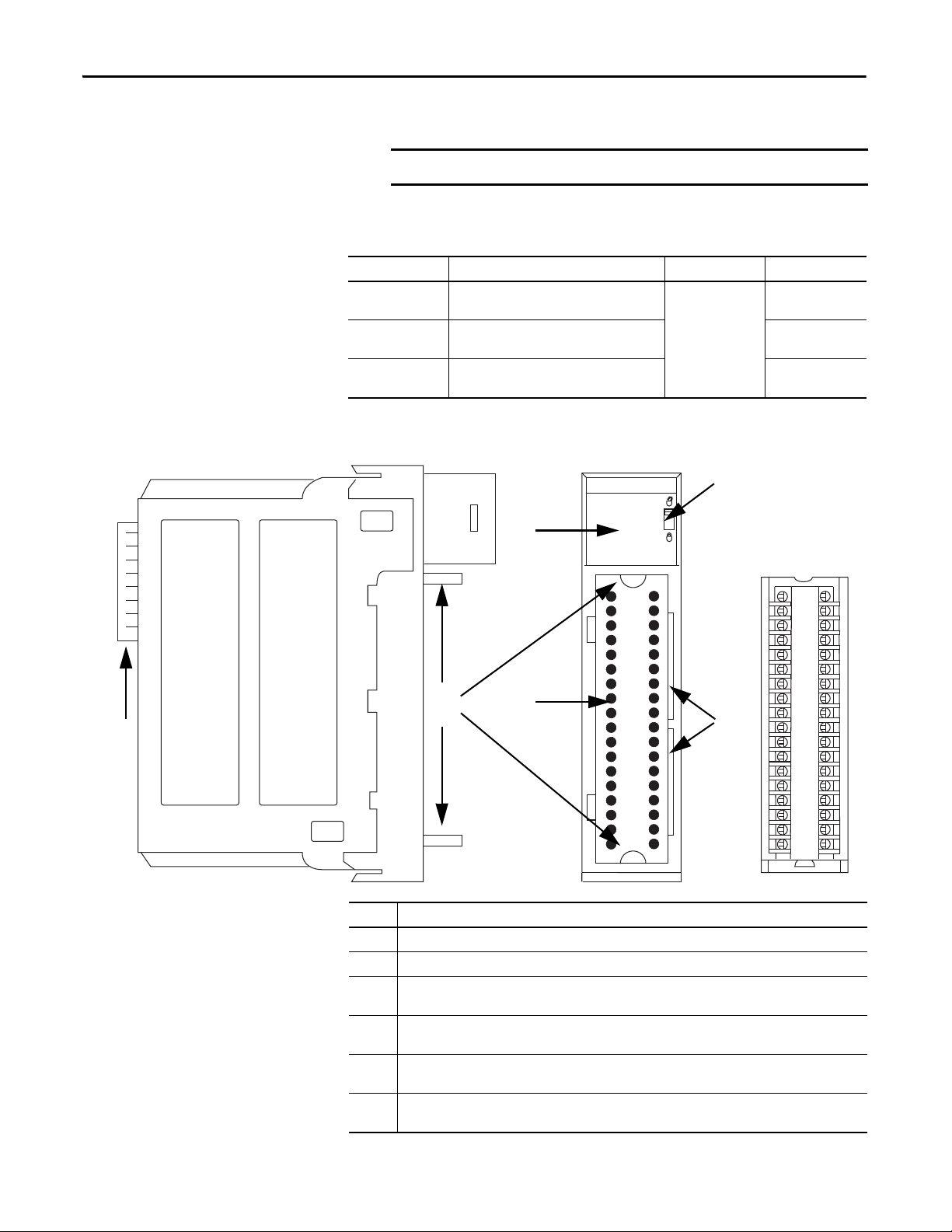
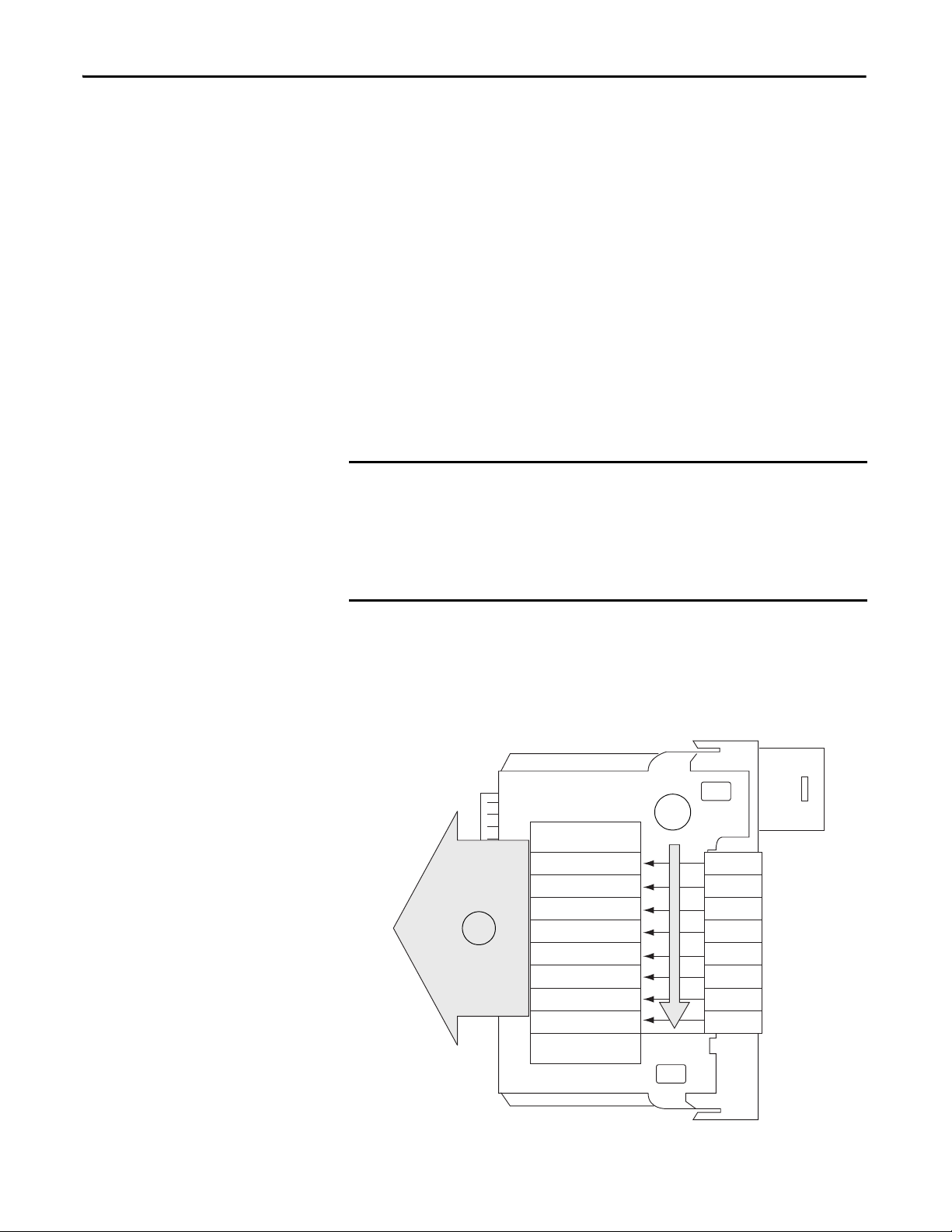
Removable Terminal Block
• Verify that you have an RTB or IFM and its components.
Table 1 - Types of ControlLogix Isolated Analog I/O Modules
Cat. No. Description RTB Used Page
1756-IF8I 8-point general purpose isolated analog
1756-IRT8I 8-point isolated combined temperature and mV
1756-OF8I 8-point general purpose isolated analog
Figure 1 - Parts Illustration of the ControlLogix Isolated Analog I/O Module
RTBs and IFMs are not included with your module purchase.
current/voltage input module
sensing input module
current/voltage output module
36-pin
(1756-TBCH or
1756-TBS6H)
45
65
93
Item Description
1 Backplane connector - Interface for the ControlLogix system that connects the module to the backplane.
2 Top and bottom guides - Guides provide assistance in seating the RTB or IFM cable onto the module.
3 Status indicators - Indicators display the status of communication, module health, and input/output
4 Connectors pins - Input/output, power, and grounding connections are made to the module through
5 Locking tab - The locking tab anchors the RTB or IFM cable on the module, maintaining wiring
6 Slots for keying - Mechanically keys the RTB to prevent inadvertently making the wrong wire connections
10 Rockwell Automation Publication 1756-UM540A-EN-P - May 2014
devices. Indicators help in troubleshooting anomalies.
these pins with the use of an RTB or IFM.
connections.
to your module.
Isolated Analog I/O Module Operation in the ControlLogix System Chapter 1
OKFORCE SDRUN
Logix5575
R
U
N
R
E
M
P
R
O
G
ANALOG INPUT
ST
FLT
O
K
ST
FLT
O
K
ANALOG OUTPUT
Controller I/O Modules
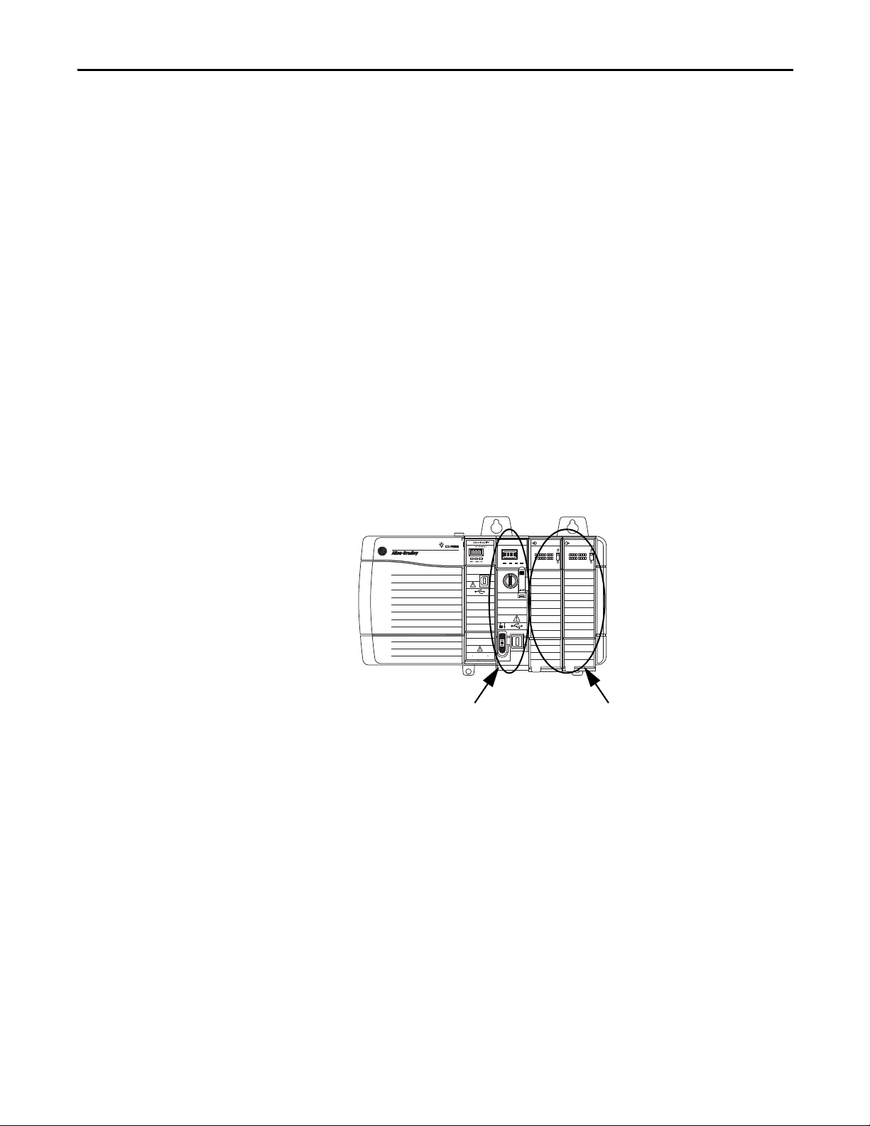
Ownership
Configure a Module
Every I/O module in the ControlLogix system must be owned by a ControlLogix
controller. This controller performs the following:
• Stores configuration data for every module that it owns.
• Resides in the local or remote chassis in regard to the I/O
module’s position.
• Sends the I/O module configuration data to define the module’s behavior
and begin operation in the control system.
Each ControlLogix I/O module must continuously maintain communication
with its owner to operate normally. Typically, each module in the system has only
one owner. Input modules can have more than one owner. Output modules,
however, are limited to a single owner.
You use the I/O configuration portion of the Logix Designer application to
configure each I/O module. An I/O module can reside in either of the following:
•Local chassis - The chassis in which the owner-controller resides.
Rockwell Automation Publication 1756-UM540A-EN-P - May 2014 11
Chapter 1 Isolated Analog I/O Module Operation in the ControlLogix System
OKFORCE SDRUN
Logix5575
R
U
N
R
E
M
P
R
O
G
ANALOG INPUT
ST
FLT
O
K
ST
FLT
O
K
ANALOG OUTPUT
ANALOG INPUT
ST
FLT
O
K
ST
FLT
O
K
ANALOG OUTPUT
ANALOG INPUT
ST
FLT
O
K
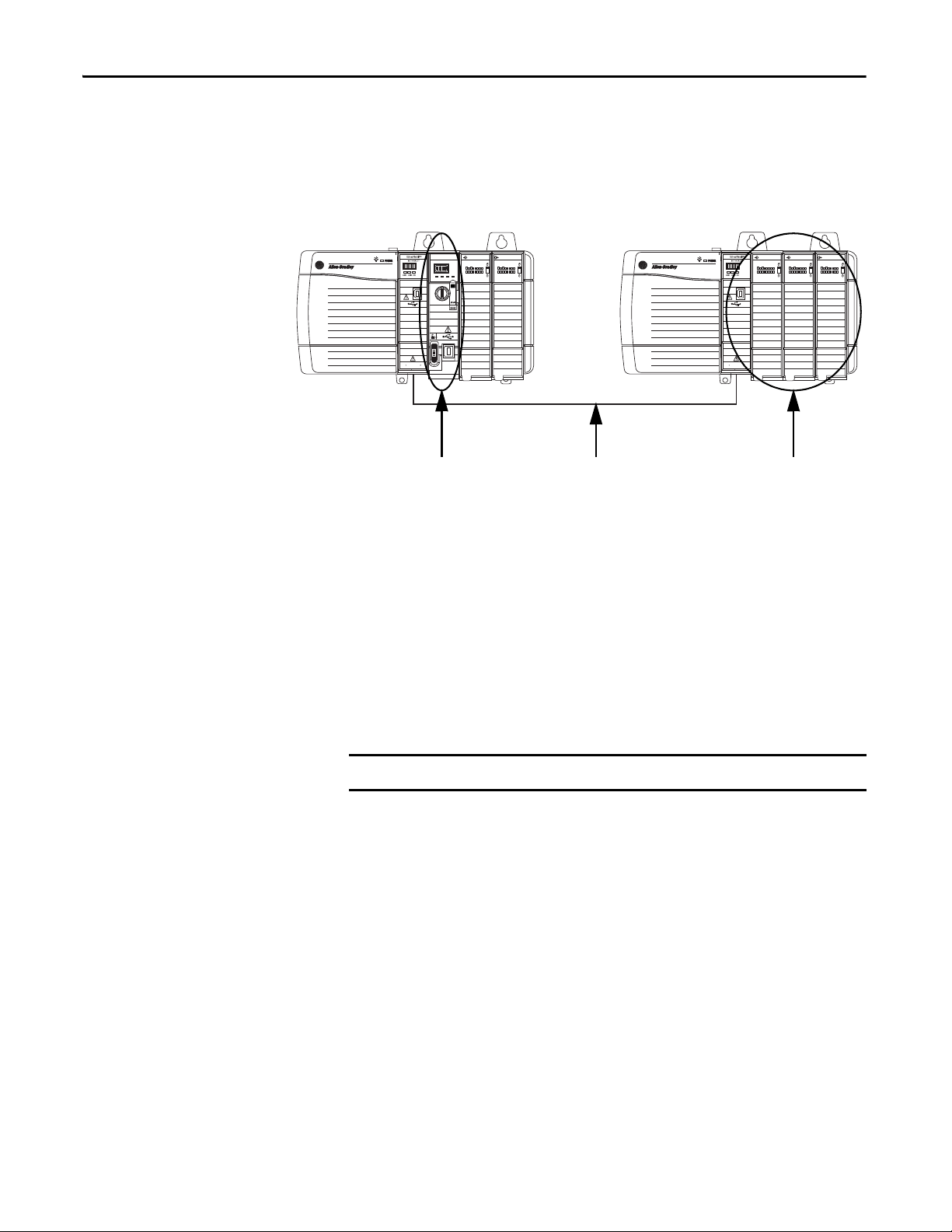
Control ler I/O Modules
Local Chassis Remote Chassis
EtherNet/IP Network
IMPORTANT
•Remote chassis - A chassis that does not contain the module’s ownercontroller but is connected to the local chassis over the EtherNet/IP
network or ControlNet network.
Direct Connections
The Logix Designer application transfers configuration data to the controller
during the program download. Subsequently, data is transferred to the I/O
modules in the local and remote chassis.
The I/O module can operate immediately after the project download from the
owner-controller is complete.
A direct connection is a real-time data transfer link between the controller and
the device that occupies the slot that the configuration references.
ControlLogix isolated analog I/O modules support only direct connections
When you download module configuration to a controller, the controller
attempts to establish a direct connection to each module referenced by the
configuration.
12 Rockwell Automation Publication 1756-UM540A-EN-P - May 2014

Isolated Analog I/O Module Operation in the ControlLogix System Chapter 1
If controller configuration refers to a chassis slot in the system, the controller
periodically checks for the presence of a device there. If a device is detected, the
controller sends the configuration, and one of the following occurs:
• If the configuration is appropriate to the module detected, a connection is
made and operation begins.
• If the configuration is not appropriate to the module detected, the data is
rejected and the Logix Designer application indicates that an error
occurred.
The configuration can be inappropriate for any of a number of reasons. For
example, a module’s configuration can include a mismatch in electronic
keying that prevents normal operation.
The controller maintains and monitors its connection with a module. Any break
in the connection, for example, the removal of the module from the chassis while
under power, causes a fault.
The Logix Designer application indicates that the fault occurred in the fault
status bits associated with the module. The Logix Designer application monitors
the fault status bits to annunciate the module’s failures.
Rockwell Automation Publication 1756-UM540A-EN-P - May 2014 13
Chapter 1 Isolated Analog I/O Module Operation in the ControlLogix System
IMPORTANT
On-Board Memory
Status Data
Channel Data
Channel Data
Channel Data
Channel Data
Channel Data
Channel Data
Ch 0
Ch 1
Ch 2
Ch 3
Ch 4
Ch 5
Timestamp
1
2
Channel Data
Channel Data Ch 6
Ch 7
Input Module Operation
In traditional I/O systems, controllers periodically poll input modules to obtain
their input status.
In the ControlLogix system, the controller does not poll the isolated analog input
modules. Instead, the modules broadcast their input data, that is, channel and
status data, to their backplane periodically.
Requested Packet Interval (RPI)
The RPI is a configurable parameter that defines a specific period of time at
which the module broadcasts input data to the backplane. Valid RPI values are
1…750 ms. The default value is 100 ms.
You set the RPI value at initial module configuration and adjust it as necessary
only when the controller is in Program mode.
Other ControlLogix analog input modules offer the Real Time Sample (RTS)
parameter that determines when channel data is scanned and stored on the
module’s on-board memory until broadcast to the chassis backplane.
The 1756-IF8I and 1756-IRT8I modules do not offer the RTS parameter.
With these modules, the channel sampling rate is exclusively determined by
the RPI value.
At the RPI, the following events occur.
1. The module scans its channels for input data.
2. The module broadcasts the data to its backplane.
14 Rockwell Automation Publication 1756-UM540A-EN-P - May 2014

Isolated Analog I/O Module Operation in the ControlLogix System Chapter 1
The input module broadcasts data to the chassis backplane immediately after
the scan:
• When the module resides in the local chassis, the controller receives the
data immediately.
• When the module resides in a remote chassis, the time elapsed before the
controller receives it depends on the configuration of the network
connecting the local and remote chassis.
For more information, see Input Modules in a Remote Chassis
.
Input Modules in a Local Chassis
When an input module resides in a local chassis, as shown on page 11, after the
input module broadcasts data to the chassis backplane, the controller receives
it immediately.
Input Modules in a Remote Chassis
When an input module resides in a remote chassis, as shown on page 12, it is
considered remote input module.
At the RPI, the following events occur.
1. The remote input module scans its channels for input data.
2. The remote input module broadcasts the data to its backplane.
3. The network communication module in the chassis with the I/O module
sends the data over the network to the controller.
Broadcast Method
The isolated analog input module broadcasts data by using one of the following
connection methods:
• Multicast - Data is sent to all network devices
• Unicast - Data is sent to a specific controller depending on the
module’s configuration
For more information on guidelines for specifying RPI rates, see the Logix5000
Controllers Design Considerations Reference Manual, publication
1756-RM094
Rockwell Automation Publication 1756-UM540A-EN-P - May 2014 15
.
Chapter 1 Isolated Analog I/O Module Operation in the ControlLogix System
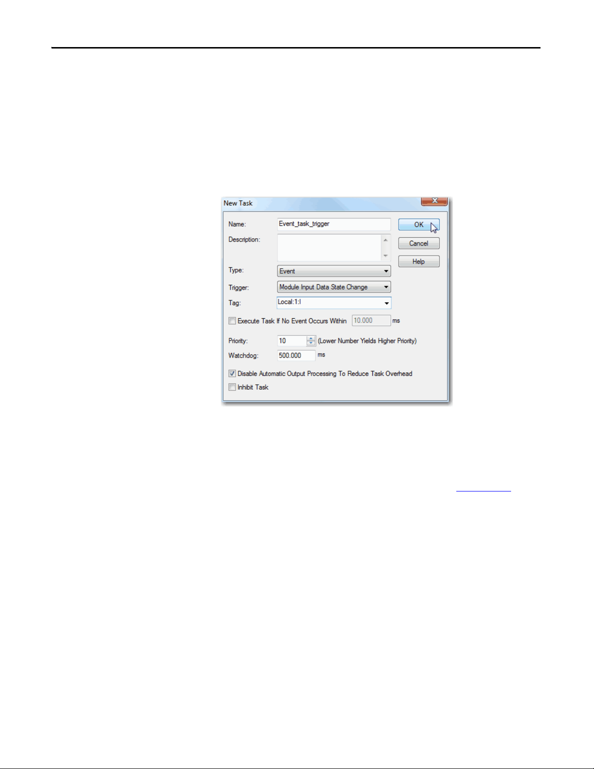
Triggering Event Tasks
ControlLogix isolated analog input modules can trigger an Event task. The Event
task causes the controller to execute a section of logic immediately when a
triggering event occurs. You can configure the Event task to be triggered if new
input data is sent at the RPI.
The following graphic shows an Event task dialog box in Logix Designer
application.
Event tasks are useful for synchronizing process variable (PV) samples and
proportional integral derivative (PID) calculations.
For more information on Event tasks, see the Logix5000 Controllers Tasks,
Programs, and Routines Programming Manual, publication 1756-PM005
.
16 Rockwell Automation Publication 1756-UM540A-EN-P - May 2014

Isolated Analog I/O Module Operation in the ControlLogix System Chapter 1
Output Module Operation
The RPI defines when a controller sends data to the isolated analog output
module and when the output module echoes data. The controller sends data to
an output module only at the RPI.
When an output module receives new data from the controller, the module
multicasts or ‘echoes’ a data value that corresponds to the signal present at its
terminals to the rest of the control system. This feature, called Data Echo
whether the output module resides in the local or remote chassis.
Depending on the value of the RPI, with respect to the length of the controller
program scan, the output module can receive and ‘echo’ data multiple times
during one program scan.
When the RPI is less than the program scan length, the module’s output channels
can change values multiple times during a single program scan. The controller
does not depend on reaching the end of the program to send data.
, occurs
Output Modules in a Local Chassis
When an output module resides in a local chassis, as shown on page 11, it receives
data almost immediately after the owner-controller sends it.
Output Modules in a Remote Chassis
When an output module resides in a remote chassis, as shown on page 12, and is
connected to the local chassis via an EtherNet/IP network, the following events
occur for the controller to send data to the output module.
1. The controller broadcasts data to its local chassis at one of the
following events:
• RPI value
• A programmed Immediate Output (IOT) instruction is executed.
An IOT sends data immediately and resets the RPI timer.
2. The 1756 ControlLogix EtherNet/IP communication module in the local
chassis broadcasts the data over the EtherNet/IP network.
3. After receiving the output data, the 1756 ControlLogix EtherNet/IP
communication in the remote chassis broadcasts the data to its backplane,
that is, the remote chassis.
4. The output module receives the data almost immediately after it is
broadcast to the remote chassis backplane.
Rockwell Automation Publication 1756-UM540A-EN-P - May 2014 17

Chapter 1 Isolated Analog I/O Module Operation in the ControlLogix System
IMPORTANT
Listen-only Mode
Any controller in the system can listen to the data from any I/O module, that is,
input data or ‘echoed’ output data, even if the controller does not own
the module.
During the I/O configuration process, you can specify a ‘Listen-Only’
connection. For more information on Connection options when configuring
your system, see page 125
When you choose a ‘Listen-Only’ connection, the controller and module
establish communication without the controller sending configuration data. In
this instance, another controller owns the I/O module.
.
If any controller uses a ‘Listen-Only’ connection to the module, none of the
other connections over the EtherNet/IP network can use the Unicast option.
The ‘Listen-Only’ controller receives multicast data from the I/O module as
long as a connection between a controller and I/O module is maintained
If the connection between all owner-controllers and the module is broken,
the module stops multicasting data and connections to all ‘Listening
controllers’ are also broken.
18 Rockwell Automation Publication 1756-UM540A-EN-P - May 2014

ControlLogix Isolated Analog I/O
Module Features
Top ic Pa ge
Common Analog I/O Features 20
Relationship between Module Resolution and Scaling 35
Calibrati on 38
Calibrated Accuracy 38
Error Calculated over Hardware Range 39
RTD and Thermocouple Error Calculations 39
Thermocouple Resolution 43
Chapter 2
ControlLogix isolated analog input modules convert an analog signal to a digital
value. The following are example analog signal types to which input modules
convert to digital values:
• Vo l t s
• Millivolts
• Milliamps
• Ohms
ControlLogix isolated analog output modules convert a digital value to an analog
signal. The following are example analog signal types to which output modules
convert digital values:
• Vo l t s
• Milliamps
Rockwell Automation Publication 1756-UM540A-EN-P - May 2014 19

Chapter 2 ControlLogix Isolated Analog I/O Module Features
Common Analog I/O Features
The ControlLogix isolated analog I/O modules have the following features:
• CIP Sync Timestamp of Data
• Rolling Timestamp of Data
• Floating Point Data Format
• Module Resolution
• Calibration
• Fault and Status Reporting
• Configurable Software
• Latching of Alarms
• Module Inhibiting
• Electronic Keying
CIP Sync Timestamp of Data
The control system uses a 64-bit system clock. The modules support CIP Sync
timestamping by using the 1588 protocol passed throughout the system. The
1588 protocol is defined in the IEEE 1588-2002 standard, publication Standard
for a Precision Clock Synchronization Protocol for Networked Measurement
and Control Systems.
Each input channel scan or new output application is stamped with a CIP Sync
timestamp and a single timestamp is returned to the controller for the module
with the input data transfer.
You can use this feature for the following:
• To identify the sequence of events in fault conditions or during normal
operation.
It is possible to use the system clock between multiple modules in the same
chassis or throughout a system in which a common Time Master is used.
• To measure the change between samples–which likely correlates closely
with the RPI if no samples are missed in the logic–and to detect when a
new sample is available for processing via the logic.
You can also use the 1588 Protocol to synchronize sampling for modules across
the entire system. By using the Synchronized Sampling feature, described in detail
on page 57
input samples precisely with each other when using the same RPI.
and page 81, you can configure multiple modules to coordinate their
20 Rockwell Automation Publication 1756-UM540A-EN-P - May 2014

ControlLogix Isolated Analog I/O Module Features Chapter 2
Synchronized Sampling lets you configure a test stand, for example, and take
many measurements simultaneously across many modules, if needed, while still
precisely coordinating the sampling. With these modules, the synchronized
sampling should coordinate within approximately ± 20 μs.
Rolling Timestamp of Data
The rolling timestamp is a continuously running 16-bit rolling timestamp that
counts in milliseconds from 0…32,767 ms; where 1 ms = 1 count.
Rolling Timestamp with the 1756-IF8I and 1756-IRT8I Modules
The 1756-IF8I and 1756-IRT8I modules scan their inputs at the RPI, update the
input data, and update the rolling timestamp value. Other ControlLogix analog
input modules scan their inputs at the RTS, not the RPI.
In either case, though, the controller program uses the last two rolling timestamp
values to calculate the interval between the receipt of data or the time at which
new data is received.
The rolling value is commonly used with instructions such as the PID and PIDE
instructions. Every time a rolling timestamp changes, a PID or PIDE instruction
is executed. When you configure a PID instruction for use with a 1756-IF8I and
1756-IRT8I module, set the loop update time equal to the module’s RPI value.
Rolling Timestamp with the 1756-OF8I Module
For the 1756-OF8I module, the rolling timestamp value is updated only when
new values are applied to the Digital to Analog Converter (DAC).
Rockwell Automation Publication 1756-UM540A-EN-P - May 2014 21

Chapter 2 ControlLogix Isolated Analog I/O Module Features
EXAMPLE
Floating Point Data Format
The modules return channel data to the owner-controller in the IEEE 32-bit
floating point data format. In your Logix Designer application, the data type is
REAL. You can configure the module to scan its channels and return data as
quickly as every 1 ms.
The floating point data format lets you change the data representation of the
selected channel. Although the full range of the module does not change, you can
scale your module to represent I/O data in specific terms for your application.
When you scale a channel, you select two points that represent signal units, that
is, a Low Signal and a High Signal. You also select two points that represent
engineering units, that is, Low Engineering and High Engineering.
The Low Signal point equates to the Low Engineering point and the High Signal
point matches the High Engineering point.
A 1756-IF8I module used in current mode maintains 0…21 mA range
capability. Your application uses a 4…20 mA transmitter.
• If you want to receive values in signal units, configure the module
as follows:
– Low Signal = 4 mA
– High Signal = 20 mA
– Low Engineering = 4 EU
– High Engineering = 20 EU
• If you want to receive values in terms of Percent of Full Scale, configure
the module as follows:
– Low Signal = 0 mA
– High Signal = 20 mA
– Low Engineering = 0%
– High Engineering = 100%
By default, module channels used in Current mode are scaled such at 4…20 mA
equate to 0…100% engineering units. Other module channels scale 1:1 with
respect to signal units and engineering units by default.
Module Resolution
The modules support the following resolutions:
• 1756-IF8I and 1756-IRT8I modules – 24-bit resolution
• 1756-OF8I module – 16-bit resolution
For more information on module resolution, see page 35
.
22 Rockwell Automation Publication 1756-UM540A-EN-P - May 2014

ControlLogix Isolated Analog I/O Module Features Chapter 2
Module Quality Reporting
The modules indicate the quality of channel data returned to the ownercontroller. Data quality represents accuracy. There are levels of data quality
reported via module input tags.
The following input tags indicate the level of data quality. In the tag names, x
represents the module channel number:
• I.Ch[x].Fault tag - This tag indicates that channel data can be completely
inaccurate and cannot be trusted for use in the application. If the tag is set
to 1, you cannot trust the data reported. You must troubleshoot the
module to correct the cause of the inaccuracy.
Common causes of inaccurate data include the following:
– An overrange or underrange condition exists.
– A wire off detection condition has occurred.
– A short circuit detection condition has occurred.
• I.Ch[x].Uncertain tag - This tag indicates that channel data can be
inaccurate but it is not known to what degree of inaccuracy. We
recommend that you do not use the data for control.
If the tag is set to 1, you know the data can be inaccurate but you must
troubleshoot the module to discover what degree of inaccuracy exists.
Common causes of uncertain data include the following:
– The channel is actively being calibrated.
– An invalid sensor offset value exists.
– The channel’s last data sample failed CRC while the most recent data
sample was valid and used.
We recommend that you monitor these tags in your program to make sure the
application is operating as expected with accurate channel input data.
Rockwell Automation Publication 1756-UM540A-EN-P - May 2014 23

Chapter 2 ControlLogix Isolated Analog I/O Module Features
Calibration
These modules use precise analog components that maintain their specifications
over time. The modules are calibrated at the factory and recalibration is not
required.
If desired, you can recalibrate the modules on a channel-by-channel or modulewide basis. For more information, see Calibrated Accuracy on page 38
choose to recalibrate the modules in the future.
if you
Fault and Status Reporting
The modules provide fault and status data along with channel data. Faults are
indicated via the status indicators on the front of the module as well as the
module tags. Status data is available via the module tags.
• For more information on fault and status reporting via module tags, see the
following:
– 1756-IF8I fault and status reporting - page 64
– 1756-IRT8I fault and status reporting - page 92
– 1756-OF8I fault and status reporting - page 102
• For more information on fault reporting via status indicators, see
Chapter 2, Troubleshoot Your Module on page 157
24 Rockwell Automation Publication 1756-UM540A-EN-P - May 2014

ControlLogix Isolated Analog I/O Module Features Chapter 2
IMPORTANT
Configurable Software
Use one of the following software applications with your module:
• RSLogix 5000 software, versions 18…20
• Logix Designer application, version 21 or later
You must install Add-on Profiles (AOP) to use the modules in any Logix
Designer application or RSLogix 5000 software project.
This publication describes configuration with Logix Designer
application. AOPs are available at:
https://download.rockwellautomation.com/esd/
download.aspx?downloadid=addonprofiles
All module feature configuration begins in the I/O configuration portion of the
Logix Designer application. In addition to enable or disable module features, you
can use the application to interrogate any module for the following
module information:
• Serial number
• Revision information
• Catalog number
• Vendor identification
• Error/fault information
• Diagnostic counters
For more information on configurable software and its use, see the
following sections:
• Preface
• Chapter 7, Configure ControlLogix Isolated Analog I/O Modules
• Chapter 8, Calibrate the ControlLogix Isolated Analog I/O Modules
• Chapter 9, Troubleshoot Your Module
Rockwell Automation Publication 1756-UM540A-EN-P - May 2014 25

Chapter 2 ControlLogix Isolated Analog I/O Module Features
IMPORTANT
IMPORTANT
Latching of Alarms
This feature latches a module alarm in the set position once the alarm is triggered.
The alarm remains on, even if the condition causing it to occur disappears, until
the alarm is unlatched.
You must manually unlatch the alarm. You can unlatch the alarm, by using one
of the following methods:
• While the project is online, click the Alarm Configuration tab on the
Module. Then click Unlatch to unlatch a specific alarm or Unlatch All to
unlatch all alarms.
• Change the module output tag for the alarm that you want to unlatch. For
example, the Ch[x].LLAlarmUnlatch tag to unlatch a Low Low Alarm.
For more information on module tags, see Appendix A, Isolated Analog I/O
Module Tag Definitions on page 173.
• Use a CIP Generic message.
For more information how to use a CIP Generic message, see Rockwell
Automation Knowledgebase article #63046, How to Reset Latched Status
of an Analog Module. You can access the article at: (Login required)
https://rockwellautomation.custhelp.com/
To see where to latch alarms, see page 131
and page 133.
Module Inhibiting
This feature suspends the connection between an owner-controller and a
module. This process can occur in either of the following ways:
• You write configuration for an I/O module but inhibit the module to
prevent it from communicating with the owner-controller.
In this case, the owner does not establish a connection and configuration is
not sent to the module until the connection is uninhibited.
• A controller owns a module and has downloaded configuration to it. Data
is currently being exchanged over the connection between the devices.
In this case, when you inhibit the module and the owner-controller
behaves as if the connection to the module does not exist.
Whenever you inhibit an output module, it enters Program mode and all
outputs change to the state configured for the Program mode. For example,
if an output module is configured so that the state of the outputs go to zero
(0) during Program mode, whenever that module is inhibited, the outputs
go to zero (0).
26 Rockwell Automation Publication 1756-UM540A-EN-P - May 2014

ControlLogix Isolated Analog I/O Module Features Chapter 2
The following examples are instances where you need to use module inhibiting:
• Multiple controllers own an analog input module. A configuration change
is required. You must make the change in the program in all controllers.
In this case, complete the following tasks.
a. Inhibit the module.
b. Change configuration in all controllers.
c. Uninhibit the module.
• You want to upgrade the module. We recommend you complete the
following tasks.
a. Inhibit the module.
b. Perform the upgrade.
c. Uninhibit the module.
• The program includes a module that you do not physically possess and you
do not want the controller to continually look for a module that does not
exist.
Inhibit the module until it physically resides in the proper slot.
To see where to inhibit a module connection, see page 126
.
Rockwell Automation Publication 1756-UM540A-EN-P - May 2014 27

Chapter 2 ControlLogix Isolated Analog I/O Module Features
Electronic Keying
The electronic keying feature automatically compares the expected module, as
shown in the I/O Configuration tree, to the physical module before I/O
communication begins. You can use electronic keying to help prevent
communication to a module that does not match the type and revision expected.
For each module in the I/O Configuration tree, the user-selected keying option
determines if, and how, an electronic keying check is performed. Typically, three
keying options are available:
• Exact Match
• Compatible Keying
• Disable Keying
You must carefully consider the benefits and implications of each keying option
when selecting between them. For some specific module types, fewer options are
available.
Electronic keying is based on a set of attributes unique to each product revision.
When a Logix5000 controller begins communicating with a module, this set of
keying attributes is considered.
Attribute Description
Vendor The manufacturer of the module, for example, Rockwell Automation/Allen-Bradley.
Product Type The general type of the module, for example, communication adapter, AC drive, or digital
Product Code The specific type of module, generally represented by its catalog number, for example,
Major Revision A number that represents the functional capabilities and data exchange formats of the
Minor Revision A number that indicates the module’s specific firmware revision. Minor Revisions
I/O.
1756-IRT8I.
module. Typically, although not always, a later, that is higher, Major Revision supports at
least all of the data formats supported by an earlier, that is lower, Major Revision of the
same catalog number and, possibly, additional ones.
typically do not impact data compatibility but can indicate performance or behavior
improvement.
28 Rockwell Automation Publication 1756-UM540A-EN-P - May 2014
ControlLogix Isolated Analog I/O Module Features Chapter 2
IMPORTANT
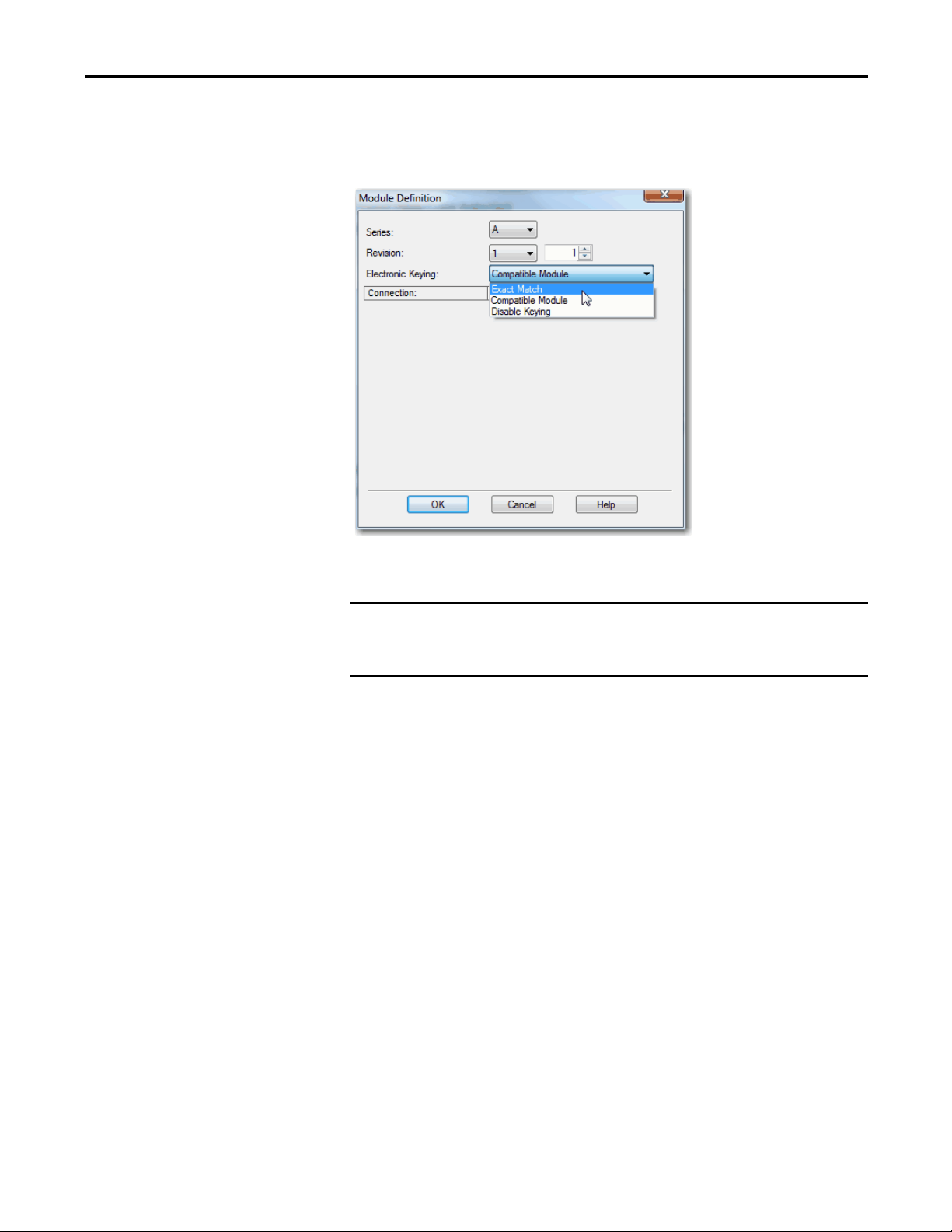
You can find revision information on the Module Definition dialog box.
Figure 2 - Module Definition Dialog Box
Changing electronic keying selections online can cause the I/O
communication connection to the module to be disrupted and can result in
a loss of data.
Rockwell Automation Publication 1756-UM540A-EN-P - May 2014 29
Chapter 2 ControlLogix Isolated Analog I/O Module Features
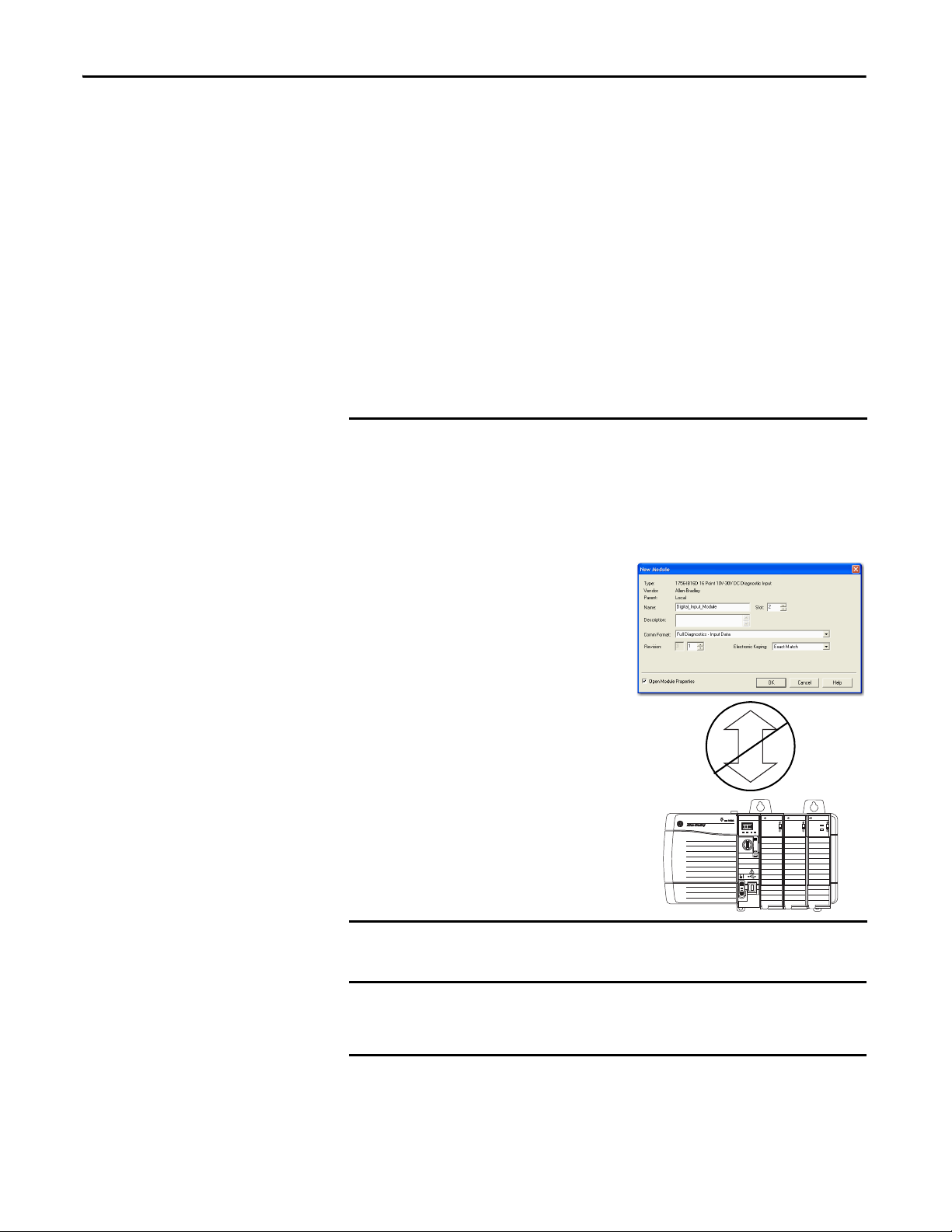
EXAMPLE
IMPORTANT
Module Configuration
Vendor = Allen-Bradley
Product Type = Digital Input Module
Catalog Number = 1756-IB16D
Major Revision = 3
Minor Revision = 1
Physical Module
Vendor = Allen-Bradley
Product Type = Digital Input Module
Catalog Number = 1756-IB16D
Major Revision = 3
Minor Revision = 2
Communication is prevented
Exact Match
Exact Match Keying requires all keying attributes, that is, Vendor, Product Type,
Product Code (catalog number), Major Revision, and Minor Revision, of the
physical module and the module created in the software to match precisely to
establish communication. If any attribute does not match precisely, I/O
communication is not permitted with the module or with modules connected
through it, as in the case of a communication module.
Use Exact Match keying when you need the system to verify that the module
revisions in use are exactly as specified in the project, such as for use in highlyregulated industries. Exact Match keying is also necessary to enable Automatic
Firmware Update for the module via the Firmware Supervisor feature from a
Logix5000 controller.
In the following scenario, Exact Match keying prevents I/O
communication:
The module configuration is for a 1756-IB16D module with module revision
3.1. The physical module is a 1756-IB16D module with module revision 3.2.
In this case, communication is prevented because the Minor Revision of the
module does not match precisely.
30 Rockwell Automation Publication 1756-UM540A-EN-P - May 2014
Logix5575
ST01234567
FLT0 12 3 4 5 6 7
ST 89 10 111213 1415
FLT89101112131415
OKFORCE SDRUN
M
E
R
P
N
R
O
U
G
R
ANALOG INPUT
DC INPUT
DC INPUT
CAL
ST0 1 2 34 5 6 7
O
O
K
K
ST 89 1011 121314 15
OK
DIAGNOSTIC
Changing electronic keying selections online can cause the I/O
Communication connection to the module to be disrupted and can result in
a loss of data.
Loading...