


 Loading...
Installation Instruction
Powermonitor 3000
(Catalog Numbers: 1404-M4, 1404-M5, 1404-M6, 1404-M8)
Inside. . . |
|
Important User Information............................................................... |
2 |
European Communities (EC) Directive Compliance........................ |
3 |
Using This Installation Instruction .................................................... |
4 |
Safety Considerations......................................................................... |
6 |
Product Description ........................................................................... |
7 |
Master Module.................................................................................... |
8 |
Display Module ................................................................................ |
10 |
LED Indicators.................................................................................. |
11 |
Quick Start Guidelines..................................................................... |
15 |
Installation ........................................................................................ |
15 |
System Accuracy Considerations..................................................... |
17 |
Wiring ............................................................................................... |
19 |
Wiring Diagrams .............................................................................. |
23 |
Communication Wiring.................................................................... |
38 |
Maintenance ..................................................................................... |
51 |
Catalog Number Explanation .......................................................... |
55 |
Dimension Drawings ....................................................................... |
56 |
Product Approvals ........................................................................... |
57 |
Technical Specifications................................................................... |
59 |
Publication 1404-IN007D-EN-P - October 2004

2 Powermonitor 3000
Important User Information Solid state equipment has operational characteristics differing from those of electromechanical equipment. Safety Guidelines for the Application,
Installation and Maintenance of Solid State Controls (Publication SGI-1.1 available from your local Rockwell Automation sales office or online at http://www.ab.com/manuals/gi) describes some important differences between solid state equipment and hard-wired electromechanical devices. Because of this difference, and also because of the wide variety of uses for solid state equipment, all persons responsible for applying this equipment must satisfy themselves that each intended application of this equipment is acceptable.
In no event will Rockwell Automation, Inc. be responsible or liable for indirect or consequential damages resulting from the use or application of this equipment.
The examples and diagrams in this manual are included solely for illustrative purposes. Because of the many variables and requirements associated with any particular installation, Rockwell Automation, Inc. cannot assume responsibility or liability for actual use based on the examples and diagrams.
No patent liability is assumed by Rockwell Automation, Inc. with respect to use of information, circuits, equipment, or software described in this manual.
Reproduction of the contents of this manual, in whole or in part, without written permission of Rockwell Automation, Inc. is prohibited.
Throughout this manual we use notes to make you aware of safety considerations.
WARNING
Identifies information about practices or circumstances that can cause an explosion in a hazardous environment, which may lead to personal injury or death, property damage, or economic loss.
IMPORTANT
Identifies information that is critical for successful application and understanding of the product.
ATTENTION
Identifies information about practices or circumstances that can lead to personal injury or death, property damage, or economic loss. Attentions help you:
• identify a hazard
• avoid a hazard
• recognize the consequence
SHOCK HAZARD Labels may be located on or inside the drive to alert people that dangerous voltage may be present.
BURN HAZARD |
Labels may be located on or inside the drive to alert |
|
people that surfaces may be dangerous temperatures. |
Publication 1404-IN007D-EN-P - October 2004

Powermonitor 3000 3
European Communities (EC)
Directive Compliance
If this product has the CE mark, it is approved for installation within the European Union and EEA regions. It has been designed and tested to meet the following directives.
EMC Directive
This product is tested to meet the Council Directive 89/336/EEC Electromagnetic Compatibility (EMC) by applying the following standards, in whole or in part, documented in a technical construction file:
•EN 50081-2 EMC — Generic Emission Standard, Part 2 — Industrial Environment
•EN 50082-2 EMC — Generic Immunity Standard, Part 2 — Industrial Environment
This product is intended for use in an industrial environment.
Low Voltage Directive
This product is tested to meet Council Directive 73/23/EEC Low Voltage, by applying the safety requirements of IEC 1010-1, Safety Requirements for Electrical Equipment for Measurement, Control, and Laboratory Use.
This equipment is classified as an open style device. Open style devices must be provided with environmental and safety protection by proper mounting in enclosures designed for specific application conditions. See NEMA Standards publication 250 and IEC publication 529, as applicable, for explanations of the degrees of protection provided by different types of enclosure.
Publication 1404-IN007D-EN-P - October 2004

4 Powermonitor 3000
Using This Installation |
What This Manual Doesn’t Contain |
|
Instruction |
This manual does not contain the following information. Except as |
|
|
||
|
noted, refer to the Powermonitor 3000 User Manual, Publication |
|
|
1404-UM001 for detailed information on the topics in this list. |
|
|
• Information on metering functionality and measurements |
|
|
• Use of the Display Module for configuration, monitoring and |
|
|
commands |
|
|
• Discussion of communications options, functionality, |
|
|
configuration and operation |
|
|
• Setpoint configuration and operation |
|
|
• Discrete I/O configuration and operation |
|
|
• Data logging including Event Log, Trend Log, Min/Max Log, |
|
|
Load Factor Log |
|
|
• Advanced features including Oscillography, Harmonic Analysis |
|
|
and Transient Detection |
|
|
• Powermonitor 3000 data tables |
|
|
• Sample ladder diagrams for communicating with the |
|
|
Powermonitor 3000 using various communications options |
|
|
• Display module installation instructions (refer to Publication |
|
|
1404-IN005) |
|
|
For More Information on Additional Power Quality Products |
|
|
Table 1 Related Documentation |
|
|
|
|
|
For this information: |
Refer to Publication: |
|
|
|
|
Powermonitor 3000 User Manual |
1404-UM001 |
|
|
|
|
Powermonitor 3000 Display Module Installation |
1404-IN005 |
|
Instructions |
|
|
|
|
|
Bulletin 1403 Powermonitor II Tutorial |
1403–1.0.2 |
|
|
|
|
Ethernet Series B Release Note |
1404-RN008 |
|
|
|
Publication 1404-IN007D-EN-P - October 2004

Powermonitor 3000 5
Terms and Conventions
In this manual, the following terms and conventions are used:
Table 2
Abbreviation |
Term |
|
|
AWG |
American Wire Gage |
|
|
CSA |
Canadian Standards Association |
|
|
CT |
Current Transformer |
|
|
DM |
Display Module |
|
|
EMI |
Electromagnetic Interference |
|
|
ID |
Identification |
|
|
IEC |
International Electrotechnical Commission |
|
|
LED |
Light Emitting Diode |
|
|
NEMA |
National Electrical Manufacturers Association |
|
|
PLC |
Programmable Logic Controller |
|
|
PT |
Potential Transformer |
|
(Also known as VT in some countries) |
|
|
RAM |
Random Access Memory |
|
|
RFI |
Radio Frequency Interference |
|
|
R I/O |
Remote Input/Output |
|
|
RMS |
Root–mean–square |
|
|
SLC |
Small Logic Controller |
|
|
SPDT |
Single Pole Double Throw |
|
|
UL |
Underwriters Laboratories |
|
|
VA |
Volt–ampere |
|
|
VAR |
Volt–ampere Reactive |
|
|
CIP |
Control and Information Protocol |
|
|
NAP |
Network Access Port |
|
|
Publication 1404-IN007D-EN-P - October 2004

6 Powermonitor 3000
Safety Considerations
ATTENTION
Only qualified personnel, following accepted safety procedures, should install, wire and service the Powermonitor 3000 and its associated components. Before beginning any work, disconnect all sources of power and verify that they are de-energized and locked out. Failure to follow these instructions may result in personal injury or death, property damage or economic loss.
ATTENTION |
Never open a current transformer (CT) secondary |
|||
circuit with primary current applied. Wiring between |
||||
|
|
|
||
|
|
|
||
|
|
|
the CTs and the Powermonitor 3000 should include a |
|
|
|
|
shorting terminal block in the CT secondary circuit. |
|
|
|
|
Shorting the secondary with primary current present |
|
|
|
|
allows other connections to be removed if needed. |
|
|
|
|
An open CT secondary with primary current applied |
|
|
|
|
produces a hazardous voltage, which can lead to |
|
|
|
|
personal injury, death, property damage or economic |
|
|
|
|
loss. |
|
|
|
|
|
|
|
The Powermonitor 3000 is not designed for nor |
|
IMPORTANT |
||
intended for use as a circuit protective device. Do |
||
|
||
|
||
|
not use this equipment in place of a motor overload |
|
|
relay or circuit protective relay. |
|
|
|
|
The relay output contacts and solid-state KYZ output |
|
IMPORTANT |
||
contacts on the Powermonitor 3000 may be used to |
||
|
||
|
||
|
control other devices through setpoint control or |
|
|
communications. The response of these outputs to a |
|
|
communications failure is configurable by the user. |
|
|
Refer to Publication 1404-UM001 for information on |
|
|
configuring the outputs. Be sure to evaluate the |
|
|
safety impact of the output configuration on your |
|
|
plant or process. |
|
|
|
Publication 1404-IN007D-EN-P - October 2004

Powermonitor 3000 7
Other Warnings
Product Description
ATTENTION |
Electrostatic discharge can damage integrated circuits |
|
or semiconductors. Follow these guidelines when |
||
|
||
|
||
|
you handle the module. |
• Touch a grounded object to discharge static potential.
•Wear an approved wrist strap-grounding device.
•Do not open the module or attempt to service internal components.
•If available, use a static safe workstation.
•When not in use, keep the module in its static shield bag.
The Bulletin 1404 Powermonitor 3000 is uniquely designed and developed to meet the needs of both producers of and users of electric power. A Powermonitor 3000 system consists of:
•Master Module which provides metering and native RS-485 communications
•Optional Display Module for configuration, commands and data display
•Optional communications port to serve data to other devices using a choice of networks
•Optional external devices and applications that display and utilize data for reporting, control and management of power and energy usage
The Powermonitor 3000 is a microprocessor-based monitoring and control device ideally suited for a variety of applications including:
•Load Profiling - Using the configurable trending utility to log power parameters such as real power, apparent power and demand, for analysis of power usage by loads over time.
•Demand Management - Understanding when and why demand charges occur allows you to make informed decisions that reduce your electrical power costs.
•Cost Allocation - Knowing your actual energy costs promotes manufacturing efficiencies.
Publication 1404-IN007D-EN-P - October 2004

8 Powermonitor 3000
Master Module
•Distribution System Monitoring - Using power parameters to show power flow, system topology and distribution equipment status.
•Emergency Load Shedding - Monitoring power usage to preserve system stability in the event of sudden utility outage.
•Power System Control - Managing system voltage, harmonic distortion and power factor.
The Powermonitor 3000 is a sophisticated modern alternative for traditional electro-mechanical metering devices. A single Powermonitor 3000 can replace many individual transducers and meters. The Powermonitor 3000 is operator-friendly and provides the user with easy to understand, accurate information in a compact economical package.
The Master Module contains the main microprocessor-based monitoring functions, including terminations for power system connections, status inputs, control outputs, a native RS-485 communications port and a port for the Display Module
Configuration
Although the Powermonitor 3000 ships from the factory with default settings, you will need to configure it for your particular requirements. You may configure the Powermonitor 3000 using the optional Display Module. Alternately, you may use an external device or application to write configuration, operational parameters and commands to the Master Module through its native or optional communications port. Refer to the Powermonitor 3000 User Manual, publication 1404-UM001 for additional detail.
Optional external applications that you may use for Powermonitor 3000 configuration include RSPower32™ and RSEnergyMetrix™ software operating on a personal computer. Contact your local Rockwell Automation sales office or distributor, or visit http://www.software.rockwell.com/ for more information on available software packages.
Publication 1404-IN007D-EN-P - October 2004

Powermonitor 3000 9
Communications
Every Powermonitor 3000 comes with a native RS-485
communications port. The RS-485 port may be configured to use the Allen-Bradley DF1 half-duplex slave protocols or Modbus RTU
slave. The native port is suitable for communicating to master devices including:
• PLC-5 , SLC 500 and ControlLogix processors
• RSLinx software with DDE/OPC server functionality
•Modbus RTU Master devices
•Other third-party devices
•Software that you develop
You may also specify Powermonitor 3000 units with optional communications ports including:
•Serial RS-232 (DF1 half-duplex or Modbus RTU slave)
•Remote I/O
•DeviceNet
•EtherNet/IP
•ControlNet
A Powermonitor 3000 may be easily integrated into a programmable controller or computer based control and monitoring system, using any of the communications methods listed above.
Publication 1404-IN007D-EN-P - October 2004

10 Powermonitor 3000
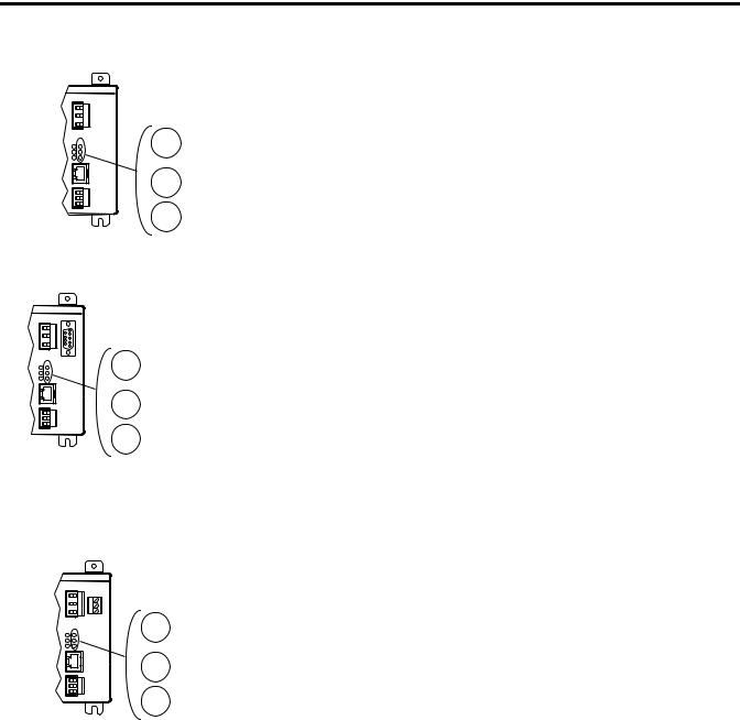
Figure 3 Master Module with Communication Options
|
Removable Status Input |
|
|
Connector |
|
Terminal Blocks |
|
|
|
LED Indicators |
|
Powermonitor 3000 |
Powermonitor 3000 |
|
|
Display Module Port |
NAP Port |
|
|
|
Optional |
|
ControlNet |
|
Channel A |
|
RS-232 Port |
|
|
|
|
|
|
|
ControlNet |
|
RS-485 (Native) |
Channel B |
|
|
|
|
Communications Port |
|
|
|
|
Auxiliary |
|
Powermonitor 3000 |
Powermonitor 3000 |
Powermonitor 3000 |
Port (not |
Powermonitor 3000 |
|
|
|
||
|
|
|
used) |
|
Optional |
Optional |
|
Optional |
Optional |
Remote I/O |
DeviceNet |
|
Ethernet |
Ethernet |
Port |
Port |
|
10BaseT |
10BaseT |
|
|
|
Port |
Port |
|
|
|
(Series A) |
(Series B) |
Display Module
The Bulletin 1404 Display Module is an optional user interface device. The Display Module provides the most economical and simplest method for setting up and configuring the Master Module for operation.
The Display Module has a highly visible, two-line LED display and four operator buttons with tactile feedback. Use the buttons and display to navigate through a series of menus for configuration, commands and data display.
Publication 1404-IN007D-EN-P - October 2004
Powermonitor 3000 11
LED Indicators
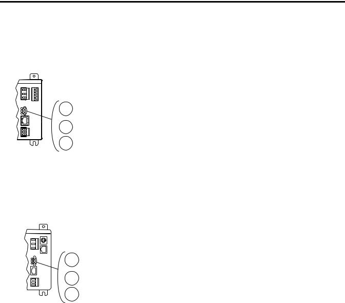
Figure 5 LED Indicators
Powermonitor 3000
MODULE
STATUS
RX
RS-485
TX
The Display Module is shipped with a 3-meter (10 ft) long, shielded 4-pair cable that provides power and serial communications between the Master Module and the Display Module. The Display Module fits into a standard ANSI four inch analog meter cutout for panel mounting. Only one Display Module may be connected to a Master Module, although you may use one Display Module to configure and monitor any number of Master Modules; one at a time.
Figure 4 Display Module
The Powermonitor 3000 is equipped with six bi-color light emitting diodes (LED’s) arranged as shown in Figure 5.
The three LED’s on the left display the same information on Powermonitor 3000 modules with any communication option including native RS-485 communications only. The three LED’s on the right have different labels and different indications depending on the communications option selected, as shown in the charts below.
Table 6 LED Indicators All Powermonitor 3000 Models
LED |
LED Color |
LED State and Communications |
|
|
Condition |
|
|
|
Module Status |
Off |
Control power is off or insufficient |
|
Steady Red |
Major fault; internal self-test has failed. If a |
|
|
power cycle does not correct the problem, |
|
|
call customer support |
|
|
|
|
Steady Green |
Powermonitor 3000 is operating normally |
|
|
|
RS-485 RX |
Off |
The RS-485 bus is idle; no active data is |
|
|
present |
|
|
|
|
Flashing Green |
Active data is present on the RS-485 bus |
|
|
|
RS-485 TX |
Off |
Powermonitor 3000 is not transmitting data |
|
|
onto the RS-485 bus |
|
|
|
|
Flashing Green |
Powermonitor 3000 is transmitting data |
|
|
onto the RS-485 bus |
|
|
|
Publication 1404-IN007D-EN-P - October 2004
12 Powermonitor 3000
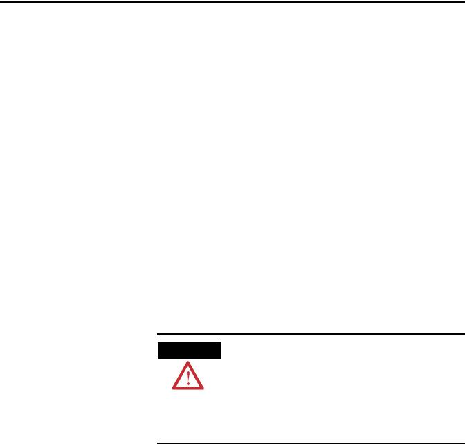
Powermonitor 3000
F1
F2
F3
Powermonitor 3000
F1
RXTX }RS-232
Powermonitor 3000
F1
F2
R I/O
Table 7 Native RS-485 Communications only (catalog numbers ending in -000)
LED |
LED Color |
LED State and Communications |
|
|
Condition |
|
|
|
F1 |
Off |
Not Used |
|
|
|
F2 |
Off |
Not Used |
|
|
|
F3 |
Off |
Not Used |
|
|
|
Table 8 RS-232 Optional Communications (catalog numbers ending in -232)
LED |
LED Color |
LED State and Communications |
|
|
Condition |
|
|
|
F1 |
Off |
Not Used |
|
|
|
RS-232 RX |
Off |
The RS-232 bus is idle; no active data is |
|
|
present |
|
|
|
|
Flashing Green |
Powermonitor 3000 is receiving data. |
|
|
|
RS-232 TX |
Off |
The Powermonitor 3000 is not transmitting |
|
|
any data onto the RS-232 bus |
|
|
|
|
Flashing Green |
The Powermonitor 3000 is transmitting |
|
|
data. |
|
|
|
Table 9 Remote I/O Optional Communications (catalog numbers ending in -RIO)
LED |
LED Color |
LED State and Communications |
|
|
Condition |
|
|
|
F1 |
Off |
Not Used |
|
|
|
F2 |
Off |
Not Used |
|
|
|
R I/O |
Off |
Remote I/O communications has not been |
|
|
established |
|
|
|
|
Flashing Green |
Remote I/O communications has been |
|
|
established but there are errors |
|
|
|
|
Steady Green |
Remote I/O communications has been |
|
|
established |
|
|
|
Publication 1404-IN007D-EN-P - October 2004
Powermonitor 3000 13
Powermonitor 3000
F1
F2
NETWORK
STATUS
Powermonitor 3000
LINK
RX
TX
Table 10 DeviceNet Optional Communications (catalog numbers ending in -DNT)
LED |
LED Color |
LED State and Communications |
|
|
Condition |
|
|
|
F1 |
Off |
Not Used |
|
|
|
F2 |
Off |
Not Used |
|
|
|
NETWORK STATUS |
Off |
Power is off or the Powermonitor 3000 is |
|
|
not online |
|
|
|
|
Flashing Green |
Network status is OK, no connections |
|
|
established |
|
|
|
|
Steady Green |
Network status is OK, connections |
|
|
established |
|
|
|
|
Flashing Red |
Recoverable communications failure; port is |
|
|
restarting |
|
|
|
|
Steady Red |
Non-recoverable communications error; |
|
|
check wiring and configuration parameters |
|
|
|
Table 11 Ethernet Optional Communications (Series A catalog numbers ending in -ENT)
LED |
LED Color |
LED State and Communications |
|
|
Condition |
|
|
|
LINK |
Off |
Ethernet connection is inactive |
|
|
|
|
Steady Green |
Ethernet connection is active |
|
|
|
RX |
Off |
Ethernet is idle, no active data present on |
|
|
port |
|
|
|
|
Flashing Red |
Active data is present on Ethernet port |
|
|
|
TX |
Off |
Powermonitor 3000 is not transmitting any |
|
|
data through the Ethernet port |
|
|
|
|
Flashing Red |
Powermonitor 3000 is transmitting data |
|
|
|
Publication 1404-IN007D-EN-P - October 2004

14 Powermonitor 3000
Powermonitor 3000
Powermonitor 3000

 LNK
LNK

 ACT
ACT
F1
F2
NETWORK STATUS
CHAN A
CHAN B
NETWORK STATUS
Table 12 Ethernet/IP Optional Communications (Series B catalog numbers ending in -ENT)
LED |
LED Color |
LED State and Communications |
|
|
Condition |
|
|
|
LNK |
Off |
No valid physical Ethernet connection |
|
|
|
|
Steady Green |
Valid physical Ethernet connection |
|
|
|
ACT |
Strobing or |
Powermonitor 3000 transmitting onto |
|
|
Ethernet |
|
Solid Yellow |
|
|
|
|
F1 |
Off |
Not Used |
|
|
|
F2 |
Off |
Not Used |
|
|
|
NETWORK STATUS |
Off |
No power |
|
|
|
|
Flashing Green |
No established connections |
|
|
|
|
Steady Green |
Connected; has at least one established |
|
|
connection |
|
|
|
|
Flashing Red |
Connection timeout; one or more |
|
|
connections to this device has timed-out |
|
|
|
|
Steady Red |
Duplicate IP; the IP address assigned to this |
|
|
device is already in use |
|
|
|
|
Flashing Green/Red |
Selftest; this device is performing a |
|
|
power-up self test |
|
|
|
Table 13 ControlNet Optional Communications (catalog numbers ending in -CNT)
LED |
LED Color |
LED State and Communications |
|
|
|
Condition |
|
|
|
|
|
CHAN A and |
Off |
No power or Channel disabled |
|
CHAN B |
|
|
|
Steady Red |
Faulted unit |
||
|
|||
|
|
|
|
|
Alternating |
Self-test |
|
|
red/green |
|
|
|
|
|
|
|
Alternating red/off |
Incorrect node configuration |
|
|
|
|
|
|
Steady green |
Normal operation |
|
|
|
|
|
|
Flashing green/off |
Temporary errors or node is not configured |
|
|
|
to go on-line |
|
|
|
|
|
|
Flashing red/off |
Media fault or no other nodes present on |
|
|
|
network |
|
|
|
|
|
|
Flashing red/green |
Incorrect network configuration |
|
|
|
|
|
Status |
Off |
Normal operation |
|
|
|
|
|
|
Flashing green |
Communication card power-up self-test |
|
|
|
|
Publication 1404-IN007D-EN-P - October 2004

Powermonitor 3000 15
Quick Start Guidelines
Installation
The Powermonitor 3000 may be used in many electric power monitoring and control systems. Whether your Powermonitor 3000 is a complete power and energy monitor or a component in a plantor enterprise-wide energy management system, there are a few basic steps to follow to make your unit operational.
1.Install your Powermonitor 3000 master module within a suitable enclosure. Refer to Installation on page 15.
2.Install your optional Display Module. Refer to the Installation Instructions included with the Display Module, publication 1404-IN005.
3.Determine your Wiring Mode and install wiring between the Powermonitor 3000 and your power system. Connect control power wiring, preferably from a separate source of control power. If used, connect wiring to the status inputs, Form C control relay, and KYZ solid-state outputs. Refer to Wiring of Master Module on page 20.
4.Configure the potential transformer (PT) and current transformer (CT) ratios to match those used in your power system connections. Configure the Voltage Mode of the Powermonitor 3000 to match your power system configuration.
5.Configure Powermonitor 3000 communications. This step varies depending upon the communications option you have selected.
6.Configure other optional performance features such as Setpoint Control, Data Logging, etc.
Refer to the Powermonitor 3000 User Manual, publication 1404-UM001, for complete information on configuring and operating your Powermonitor 3000.
Only qualified personnel should install, wire, service and maintain this equipment. Refer to and follow the safety guidelines found starting at page 6 and pay attention to all warnings and notices in these instructions.
Publication 1404-IN007D-EN-P - October 2004

16 Powermonitor 3000
Prevent Electrostatic Discharge
ATTENTION |
Electrostatic discharge can damage integrated circuits |
|
or semiconductors. Follow these guidelines when |
||
|
||
|
||
|
you handle the module. |
• Touch a grounded object to discharge static potential.
• Wear an approved wrist strap grounding device.
• Do not open the module or attempt to service internal components.
• If available, use a static safe work station.
• When not in use, keep the module in its static shield bag.
Mounting of Master Module
Mount the Powermonitor 3000 Master Module in a suitable protective enclosure. Select an enclosure that will protect the Master Module from atmospheric contaminants such as oil, water, moisture, dust corrosive vapors and other harmful airborne substances. The enclosure should also protect against personnel contact with energized circuits. The ambient temperature within the enclosure must remain within the limits listed in the Specifications, page 61.
Select an enclosure that will provide adequate clearance for ventilation and wiring for the Powermonitor 3000 and other equipment to be installed within the enclosure. See Figure 41 and Figure 42 for dimensions and spacing guidelines for the Powermonitor 3000.
Mount the Master Module so that the metal grounding clips on the bottom of the mounting feet make direct contact with the enclosure mounting panel. If the mounting panel is painted, scrape or sand the paint down to bare metal. Use star washers to assure good long-term electrical contact with the mounting panel. Ensure that the mounting panel is properly connected to a low-impedance earth ground.
Mount the enclosure in a position that allows full access to the Powermonitor 3000 Master Module. Install the Master Module with the ventilation slots in the bottom and top of the unit unobstructed to assure adequate free convection cooling of its internal electronic components.
Publication 1404-IN007D-EN-P - October 2004

Powermonitor 3000 17
System Accuracy
Considerations
|
Use caution not to block the ventilation slots of the |
|
IMPORTANT |
||
Master Module. All wiring and other obstructions |
||
|
||
|
||
|
must be a minimum of 50 mm (2.0 inches) from the |
|
|
top and bottom of the unit. |
|
|
|
See Figure 41 on page 56 for mounting hole dimensions. Mount the Master Module with four (4) No. 8-32 UNC or M4 screws with flat washers and lock washers.
User supplied potential transformers (PTs) and current transformers (CTs), as well as wiring from the CTs to the Powermonitor, may reduce the accuracy of your Powermonitor 3000 system. The quality of the Powermonitor 3000’s measurements can be no better than the quality of the signals presented to its input terminals. It is the user’s responsibility to select transformers that are adequate for the desired metering accuracy.
ANSI/IEEE C57.13, Requirements for Instrument Transformers, defines three classes of transformer accuracy: class 1.2, class 0.6, and class 0.3. The application should dictate the transformer accuracy class to be used.
PTs and CTs may introduce errors in three areas: ratio errors, phase errors, and bandwidth errors.
Ratio Errors
The voltage ratio of a PT is the number of primary turns of wire divided by the number of secondary turns. Manufacturing tolerances may cause the ratio to be slightly different than the design specifies, causing an error affecting the voltage input to the Powermonitor 3000.
Likewise, the current ratio of a CT is a function of the ratio of the number of turns of wire on the primary and secondary. Some error in this ratio is quite common in commercial grade PTs and CTs.
Other errors include magnetic core losses, winding impedance, and the burden, or load, on the transformer secondary. The combination of these errors is known as “Ratio Error”. You may compensate for Ratio Error, if known, by adjusting the Basic Configuration entries for PT and CT primary or secondary voltages.
Publication 1404-IN007D-EN-P - October 2004

18 Powermonitor 3000
For a PT the Ratio Error increases as the transformer’s load current increases, so its total load impedance should be as high as possible. Conversely, a CT’s Ratio Error increases as the voltage supported by the transformer secondary increases, so its total load impedance, including the impedance of the wire connecting the CTs to the metering device, should be as low as possible. This is why #12 AWG or larger is usually recommended for wiring CTs with a 5 amp secondary rating.
Phase Error
Phase shift between the primary to secondary signals is another source of inaccuracy introduced by the user-supplied PTs and CTs. Phase shift is generally not of concern for simple voltage or current measurements. When these signals are combined, for instance when calculating line to line voltage or phase power, the effect of phase shift can become significant. The difference in phase error among different transformers causes measurement errors. If all the PTs and CTs introduced a five-degree phase shift, there would be no error in the measured quantities. If on the other hand the PTs had a phase error of one degree and the CTs had a phase error of six degrees, there would be a five-degree phase error in the power calculation. This would show up as power factor and reactive power (VAR) errors. Phase errors can not be corrected by adjusting the Powermonitor 3000 configuration since the errors change based on varying conditions of the power system.
A typical PT phase error varies from ±1° to ±0.25° depending on the PT’s accuracy class. Applying higher than rated voltage increases the phase error and may saturate the transformer and cause even larger errors.
The phase error in a CT increases as its current decreases, and is lowest when the current is greater than 80% of the CT rating. Because significant phase error can occur when CT current is less than 20% of rated current, CTs sized for protection do not perform well when used for metering.
The phase error of both PTs and CTs are also affected by the power factor of the load on the secondary. For best accuracy, loads should be resistive, with PT loads as high as possible and CT loads as low as possible.
Publication 1404-IN007D-EN-P - October 2004
Powermonitor 3000 19
Bandwidth Error
For fundamental 50 Hz or 60 Hz measurements, bandwidth error has no affect on accuracy. However, for waveforms with significant harmonic content, the user-supplied PTs and CTs may attenuate higher harmonics. Most instrument quality PTs have a flat frequency response out to 3 kHz, or the 50th harmonic on a 60 Hz system. Current transformers, especially older, existing units, tend to be less linear, with a flat response only out to 300 Hz, or the fifth (60 Hz) harmonic. Wide-band instrument CTs are available for improved frequency response. Bandwidth error cannot be corrected by adjusting the Powermonitor 3000 configuration.
In addition, operation of either the PTs or CTs at extremely low frequencies may also cause saturation and resulting magnitude and phase errors.
For more detailed information on instrument transformer accuracy and power measurement, refer to publication 1403-1.0.2, “Bulletin 1403 Powermonitor II Tutorial”.
Wiring
ATTENTION
Only qualified personnel, following accepted safety procedures, should install, wire and service the Powermonitor 3000 and its associated components. Before beginning any work, disconnect all sources of power and verify that they are de-energized and locked out. Failure to follow these instructions may result in personal injury or death, property damage or economic loss.
Wiring of the Powermonitor 3000 includes the following steps:
•Connection of voltage and current signals from PTs and CTs
•Connection of control power
•Connection of status inputs and status/control outputs
•Communications wiring
Please follow these guidelines to help assure reliable, trouble-free operation of your Powermonitor 3000.
Publication 1404-IN007D-EN-P - October 2004

20 Powermonitor 3000
•Install and connect all wiring in a neat and workmanlike manner. Use wire tags to identify connections. Bundle wiring neatly and maintain a minimum of 50 mm (2.0 inches) clearance from the Master Module ventilation slots to avoid a buildup of heat within the unit
•Furnish and install properly-selected fuses for voltage signals and control power
•Use 600 volt wiring rated at 75°C (167°F) or higher. We strongly recommend the use of flame-retardant wire rated VW-1 by Underwriters Laboratories
•Use a shorting terminal block (provided by customer) for CT wiring, to permit servicing connected equipment such as the Powermonitor 3000 Master Module without de-energizing the power system
•Use ring lugs or locking spade lugs for voltage and current connections to provide additional wiring security and safety
•Pay careful attention to correct phasing and polarity for proper operation
•Connect the Master Module to a low-impedance earth ground using its grounding terminal and a dedicated grounding wire at least as large as the largest current-carrying wire connected to the Master Module. Keep grounding wiring as short as possible. To obtain maximum EMI immunity, the Master Module mounting feet should make electrical contact with the mounting panel. Refer to Mounting of Master Module on page 16 for additional information.
•Connect all equipment ground terminals (Master Module, PT and CT secondary) to a single point, low impedance earth ground
For information on wire sizes and types for grounding electrical equipment, refer to publication 1770-4.1, Industrial Automation Wiring and Grounding Guidelines for Noise Immunity or the National Electric Code published by National Fire Protection Association (NFPA).
Wiring of Master Module
Terminal Blocks Wire Sizes and Screw Torques - Observe all wire lug sizes and screw torques. Refer to Technical Specifications on page 59.
Publication 1404-IN007D-EN-P - October 2004
Loading...