


 Loading...
MicroLogix™
Ethernet Interface
1761-NET-ENI and
1761-NET-ENIW
User Manual

Important User Information Solid state equipment has operational characteristics differing from those of electromechanical equipment. Safety Guidelines for the Application,
Installation and Maintenance of Solid State Controls (Publication SGI-1.1 available from your local Rockwell Automation sales office or online at http://www.ab.com/manuals/gi) describes some important differences
between solid state equipment and hard-wired electromechanical devices. Because of this difference, and also because of the wide variety of uses for solid state equipment, all persons responsible for applying this equipment must satisfy themselves that each intended application of this equipment is acceptable.
In no event will Rockwell Automation, Inc. be responsible or liable for indirect or consequential damages resulting from the use or application of this equipment.
The examples and diagrams in this manual are included solely for illustrative purposes. Because of the many variables and requirements associated with any particular installation, Rockwell Automation, Inc. cannot assume responsibility or liability for actual use based on the examples and diagrams.
No patent liability is assumed by Rockwell Automation, Inc. with respect to use of information, circuits, equipment, or software described in this manual.
Reproduction of the contents of this manual, in whole or in part, without written permission of Rockwell Automation, Inc. is prohibited.
Throughout this manual we use notes to make you aware of safety considerations.
WARNING
Identifies information about practices or circumstances that can cause an explosion in a hazardous environment, which may lead to personal injury or death, property damage, or economic loss.
IMPORTANT
Identifies information that is critical for successful application and understanding of the product.
ATTENTION
Identifies information about practices or circumstances that can lead to personal injury or death, property damage, or economic loss. Attentions help you:
• identify a hazard
• avoid a hazard
• recognize the consequence
SHOCK HAZARD Labels may be located on or inside the drive to alert people that dangerous voltage may be present.
BURN HAZARD |
Labels may be located on or inside the drive to alert |
|
people that surfaces may be dangerous temperatures. |

Summary of Changes
The information below summarizes the changes to this manual since the last printing.
To help you find new and updated information in this release of the manual, we have included change bars as shown to the right of this paragraph.
Information on 1761-NET-ENI and 1761-NET-ENIW, series D, has been added throughout the manual. The table below lists the sections that document new features and additional or updated information on existing features.
For this information: |
See |
|
|
how to obtain a manual from Rockwell Automation |
P-2 |
|
|
Series D LED description |
page 1-3 |
|
|
Ethernet Settings |
page 1-6 |
|
|
Series D Enhancements |
page 1-8 |
|
|
Using the RSLinx Ethernet/IP driver with series B ENIs and higher |
page 3-5 |
|
|
Download location for ENI/ENIW Configuration Utility |
page 4-1 |
|
|
Download location for Com Port Redirector software |
page 4-1 |
|
|
Updated examples and information on making configuration settings |
pages 4-2 to 4-4 |
using the ENI/ENIW Configuration Utility, including series D |
|
configuration options |
|
|
|
Series D Email Authentication |
pages 4-5 and |
|
6-2 |
|
|
Updated information on using the ENI/ENIW Configuration Utility over |
page 4-6 |
RS-232 |
|
|
|
New information on using the ENI/ENIW Configuration Utility over |
pages 4-8 |
Ethernet (series D only), including using the Com Port Redirector |
|
software |
|
|
|
Updated information on configuration node functions |
page 4-12 |
|
|
Configuring Email Authentication options for series D ENI/ENIWs |
pages 4-20 to |
|
4-21 |
|
|
Configuring Ethernet speed and duplex settings for series D |
page 4-22 |
ENI/ENIWs |
|
|
|
Series D Web Page Enhancements |
chapter 7 |
|
|
LED sequence at power-up for series A/B/C/D |
page 9-2 |
|
|
Troubleshooting using the LED indicators series A/B/C/D |
page 9-3 |
|
|
Series C and D Ethernet specifications |
page A-1 |
|
|
Updated information on configuration via BOOTP |
Appendix B |
|
|
1761-NET-ENI/ENIW performance considerations |
Appendix C |
|
|
Publication 1761-UM006E-EN-P - August 2005

2 Summary of Changes
Publication 1761-UM006E-EN-P - August 2005

|
Table of Contents |
|
|
Preface |
|
|
Who Should Use this Manual. . . . . . . . . . . . . . . . . . . . . . . |
P-1 |
|
Purpose of this Manual . . . . . . . . . . . . . . . . . . . . . . . . . . . |
P-1 |
|
Related Documentation . . . . . . . . . . . . . . . . . . . . . . . . |
P-2 |
|
Common Techniques Used in this Manual . . . . . . . . . . . . . |
P-2 |
|
Your Questions or Comments on this Manual. . . . . . . . . . . |
P-3 |
|
Chapter 1 |
|
Product Overview |
EtherNet/IP Connectivity . . . . . . . . . . . . . . . . . . . . . . . . . . |
1-1 |
|
Hardware Features . . . . . . . . . . . . . . . . . . . . . . . . . . . . . . |
1-2 |
|
Product Drawing . . . . . . . . . . . . . . . . . . . . . . . . . . . . . |
1-2 |
|
LED Indicators . . . . . . . . . . . . . . . . . . . . . . . . . . . . . . . |
1-2 |
|
Default Settings . . . . . . . . . . . . . . . . . . . . . . . . . . . . . . |
1-5 |
|
Operating Modes . . . . . . . . . . . . . . . . . . . . . . . . . . . . . . . |
1-7 |
|
Messaging . . . . . . . . . . . . . . . . . . . . . . . . . . . . . . . . . . |
1-7 |
|
Email. . . . . . . . . . . . . . . . . . . . . . . . . . . . . . . . . . . . . . |
1-7 |
|
Device Compatibility . . . . . . . . . . . . . . . . . . . . . . . . . . . . . |
1-7 |
|
Series B Enhancements . . . . . . . . . . . . . . . . . . . . . . . . . . . |
1-7 |
|
Series C Enhancements . . . . . . . . . . . . . . . . . . . . . . . . . . . |
1-8 |
|
Series D Enhancements . . . . . . . . . . . . . . . . . . . . . . . . . . . |
1-8 |
|
Ethernet Networks . . . . . . . . . . . . . . . . . . . . . . . . . . . . . . |
1-8 |
|
Basic Ethernet Topology . . . . . . . . . . . . . . . . . . . . . . . |
1-8 |
|
Web Server Functionality. . . . . . . . . . . . . . . . . . . . . . . . . . |
1-9 |
|
Chapter 2 |
|
Installation and Wiring |
European Communities (EC) Directive Compliance . . . . . . |
2-1 |
|
EMC Directive . . . . . . . . . . . . . . . . . . . . . . . . . . . . . . . |
2-1 |
|
Low Voltage Directive . . . . . . . . . . . . . . . . . . . . . . . . . |
2-1 |
|
Safety Considerations . . . . . . . . . . . . . . . . . . . . . . . . . . . . |
2-2 |
|
External Power Supply Wiring . . . . . . . . . . . . . . . . . . . . . . |
2-3 |
|
Mounting . . . . . . . . . . . . . . . . . . . . . . . . . . . . . . . . . . . . . |
2-3 |
|
DIN Rail Mounting . . . . . . . . . . . . . . . . . . . . . . . . . . . . |
2-4 |
|
Panel Mounting . . . . . . . . . . . . . . . . . . . . . . . . . . . . . . |
2-4 |
|
ENI/ENIW Port Identification. . . . . . . . . . . . . . . . . . . . . . . |
2-5 |
|
Ethernet Connections . . . . . . . . . . . . . . . . . . . . . . . . . . . . |
2-5 |
|
Ethernet 8-Pin 10/100-Base-T Connector (Port 1). . . . . . |
2-5 |
|
Ethernet Cables . . . . . . . . . . . . . . . . . . . . . . . . . . . . . . |
2-6 |
|
Maintain ENI and ENIW Cable Connections . . . . . . . . . |
2-6 |
|
RS-232 Port Connections . . . . . . . . . . . . . . . . . . . . . . . . . . |
2-7 |
|
RS-232 Connector . . . . . . . . . . . . . . . . . . . . . . . . . . . . |
2-7 |
|
RS-232 Cables . . . . . . . . . . . . . . . . . . . . . . . . . . . . . . . |
2-7 |
Publication 1761-UM006E-EN-P - August 2005

iv |
Table of Contents |
|
|
Operation
ENI/ENIW Configuration (Nodes 241 to 254)
Chapter 3
Operation Overview . . . . . . . . . . . . . . . . . . . . . . . . . . . . . 3-1 Allocation of Ethernet Connections . . . . . . . . . . . . . . . . . . 3-1 ENI and ENIW Functional Overview . . . . . . . . . . . . . . . . . 3-2 General Ethernet Information . . . . . . . . . . . . . . . . . . . . . . 3-2 RSLinx/RSWho Connectivity Example Using ENI/ENIW Interface . . . . . . . . . . . . . . . . . . . . . . . . . . . . . . . . . . . . . . 3-2
PC Connected Directly to Ethernet (RSLinx on Ethernet) 3-4 PC Connected to Ethernet via the ENI or ENIW. . . . . . . 3-8
Chapter 4
Configuration Methods . . . . . . . . . . . . . . . . . . . . . . . . . . . 4-1 ENI/ENIW Configuration Utility . . . . . . . . . . . . . . . . . . . . . 4-1 Make Configuration Settings . . . . . . . . . . . . . . . . . . . . . 4-2 Save to ENI/ENIW RAM or ENI/ENIW ROM . . . . . . . . . 4-4 Email Settings . . . . . . . . . . . . . . . . . . . . . . . . . . . . . . . 4-5 Message Routing . . . . . . . . . . . . . . . . . . . . . . . . . . . . . 4-5 Reset . . . . . . . . . . . . . . . . . . . . . . . . . . . . . . . . . . . . . . 4-6 Use the Configuration Utility Over RS-232 . . . . . . . . . . . 4-6
Use the Configuration Utility Over Ethernet
(Series D only). . . . . . . . . . . . . . . . . . . . . . . . . . . . . . . 4-8 Controller Messaging. . . . . . . . . . . . . . . . . . . . . . . . . . . . . 4-12 ENI/ENIW Configuration Parameters . . . . . . . . . . . . . . . . . 4-12 Node 254 - Ethernet Hardware Address . . . . . . . . . . . . 4-13 Node 253 - Baud Rate . . . . . . . . . . . . . . . . . . . . . . . . . 4-14 Node 252 - BOOTP Configuration . . . . . . . . . . . . . . . . 4-15 Node 251 - Email Server. . . . . . . . . . . . . . . . . . . . . . . . 4-15 Node 250 - TCP/IP Configuration . . . . . . . . . . . . . . . . . 4-15 Node 249 - From String . . . . . . . . . . . . . . . . . . . . . . . . 4-19 Node 248 - Save/Reset Function . . . . . . . . . . . . . . . . . . 4-19 Node 245 - Configuration Security Mask . . . . . . . . . . . . 4-20
Node 244 - SMTP Email Authentication Checkbox
(Series D Only) . . . . . . . . . . . . . . . . . . . . . . . . . . . . . . 4-20 Node 243 - SMTP Email Authentication Password
(Series D Only) . . . . . . . . . . . . . . . . . . . . . . . . . . . . . . 4-21 Node 242 - SMTP Email Authentication Username
(Series D Only) . . . . . . . . . . . . . . . . . . . . . . . . . . . . . . 4-21 Node 241 - Ethernet Speed and Duplex Setting
(Series D Only) . . . . . . . . . . . . . . . . . . . . . . . . . . . . . . 4-22 Configuring ENI/ENIW Data Parameters. . . . . . . . . . . . . . . 4-22 Configuring ENI/ENIW String Parameters . . . . . . . . . . . . . . 4-24 Configuring the ENI/ENIW Email From String . . . . . . . . 4-24
Publication 1761-UM006E-EN-P - August 2005

Table of Contents |
v |
|
|
Peer-to-Peer Messaging
EMail Messages (Node 50 to 99)
1761-NET-ENIW Web Server
Capabilities
Connecting CompactLogix Controllers on Ethernet
Chapter 5
Messaging Between the ENI/ENIW and DF1 Devices . . . . . 5-1 Message to Configuration Nodes (Nodes 100 to 149) and Sending a Message to a Destination Controller (Nodes 0 to 49) . . . . 5-2
Chapter 6
Overview . . . . . . . . . . . . . . . . . . . . . . . . . . . . . . . . . . . . . 6-1 Configuring Email . . . . . . . . . . . . . . . . . . . . . . . . . . . . . . . 6-2 SMTP Email Address . . . . . . . . . . . . . . . . . . . . . . . . . . 6-2 Destination Addresses . . . . . . . . . . . . . . . . . . . . . . . . . 6-3 Message Text. . . . . . . . . . . . . . . . . . . . . . . . . . . . . . . . 6-3 Message Fields (to, from, subject) . . . . . . . . . . . . . . . . . 6-4 Sending an Email Message. . . . . . . . . . . . . . . . . . . . . . . . . 6-4
Chapter 7
Web Browser Compatibility . . . . . . . . . . . . . . . . . . . . . . . . 7-1 Series D ENIW Web Pages. . . . . . . . . . . . . . . . . . . . . . . . . 7-1 Home Page. . . . . . . . . . . . . . . . . . . . . . . . . . . . . . . . . . . . 7-2 Defining URL Links . . . . . . . . . . . . . . . . . . . . . . . . . . . . . . 7-3 Displaying Device Data . . . . . . . . . . . . . . . . . . . . . . . . . . . 7-5
String Data . . . . . . . . . . . . . . . . . . . . . . . . . . . . . . . . . 7-5 Integer Data . . . . . . . . . . . . . . . . . . . . . . . . . . . . . . . . 7-6 Floating-point Data . . . . . . . . . . . . . . . . . . . . . . . . . . . 7-7 Writing Data to the ENIW. . . . . . . . . . . . . . . . . . . . . . . 7-8 Auto-Refresh of Data View Pages . . . . . . . . . . . . . . . . . 7-9
ENIW Update Timer . . . . . . . . . . . . . . . . . . . . . . . . . . . . . 7-9 Posting Data to the Device . . . . . . . . . . . . . . . . . . . . . . . . 7-10 Setting Passwords for Data View Pages . . . . . . . . . . . . . 7-10 Posting Data . . . . . . . . . . . . . . . . . . . . . . . . . . . . . . . . 7-10 Display Event Data . . . . . . . . . . . . . . . . . . . . . . . . . . . . . . 7-11 Display Diagnostic Data . . . . . . . . . . . . . . . . . . . . . . . . . . 7-12 Display Configuration . . . . . . . . . . . . . . . . . . . . . . . . . . . . 7-13
Use the ENIW Utility to Configure the ENIW’s Web Server Functionality. . . . . . . . . . . . . . . . . . . . . . . . . . . . . . . . . . . 7-14
Configure the Home Page . . . . . . . . . . . . . . . . . . . . . . 7-14 Configure Data View Pages . . . . . . . . . . . . . . . . . . . . . 7-14
Chapter 8
System Diagram . . . . . . . . . . . . . . . . . . . . . . . . . . . . . . . . 8-2
Purpose . . . . . . . . . . . . . . . . . . . . . . . . . . . . . . . . . . . . . . 8-3
Scope . . . . . . . . . . . . . . . . . . . . . . . . . . . . . . . . . . . . . . . . 8-3
General CompactLogix Messaging Guidelines. . . . . . . . . . . 8-4
Configure ENI #1 . . . . . . . . . . . . . . . . . . . . . . . . . . . . . . . 8-5
Configure ENI #2 . . . . . . . . . . . . . . . . . . . . . . . . . . . . . . . 8-7
Configure ENI #2 Via the ENI/ENIW Configuration Utility 8-8
Publication 1761-UM006E-EN-P - August 2005

vi |
Table of Contents |
|
|
Troubleshooting
Specifications
BOOTP Configuration Method (default)
1761-NET-ENI/ENIW Performance
Considerations
Configuration Via Ladder Logic. . . . . . . . . . . . . . . . . . . 8-10 Download To The CompactLogix Controller Through Two Series A ENIs . . . . . . . . . . . . . . . . . . . . . . . . . . . . . . . . . . . . . . . 8-17 Download to the CompactLogix Controller Through a ENI/ENIW Series B/C/D via Ethernet . . . . . . . . . . . . . . . . . . . . . . . . . 8-19 Create MSG Programs for the SLC 5/05 and the ControlLogix Controllers . . . . . . . . . . . . . . . . . . . . . . . . . . . . . . . . . . . . 8-21
Chapter 9
Network Troubleshooting . . . . . . . . . . . . . . . . . . . . . . . . . 9-1 Maintain ENI/ENIW Cable Connections. . . . . . . . . . . . . 9-1 Using ENI/ENIW with Routers . . . . . . . . . . . . . . . . . . . . . . 9-1 LED Sequence at Power-Up. . . . . . . . . . . . . . . . . . . . . . . . 9-2 Troubleshooting Using the LED Indicators . . . . . . . . . . . . . 9-3 Error Codes Generated by the ENI/ENIW. . . . . . . . . . . . . . 9-6
Appendix A
Physical Specifications. . . . . . . . . . . . . . . . . . . . . . . . . . . . A-1
Series C and D Ethernet Specifications . . . . . . . . . . . . . . . . A-1
MicroLogix Web Site . . . . . . . . . . . . . . . . . . . . . . . . . . . . . A-1
Dimensions. . . . . . . . . . . . . . . . . . . . . . . . . . . . . . . . . . . . A-2
Appendix B
ENI/ENIW BOOTP Operation . . . . . . . . . . . . . . . . . . . . . . B-2
Using the Rockwell BOOTP/DHCP Utility . . . . . . . . . . . . . B-3
Appendix C
Ethernet/IP Connections . . . . . . . . . . . . . . . . . . . . . . . . . . C-1
Packet Size Limitations . . . . . . . . . . . . . . . . . . . . . . . . . C-1
Data Throughput . . . . . . . . . . . . . . . . . . . . . . . . . . . . . C-2
Glossary
Index
Publication 1761-UM006E-EN-P - August 2005

Preface
Who Should Use this Manual
Purpose of this Manual
Read this preface to familiarize yourself with the rest of the manual. It provides information concerning:
•who should use this manual
•the purpose of this manual
•related documentation
•conventions used in this manual
•Rockwell Automation support
Use this manual if you are responsible for designing, installing, programming, or troubleshooting control systems that use Allen-Bradley Controllers on Ethernet.
You should have a basic understanding of Allen-Bradley programmable controllers and Ethernet networking. You should understand programmable controllers and be able to interpret the ladder logic instructions required to control your application. If you do not, contact your local Allen-Bradley representative for information on available training courses before using this product.
This manual is a reference guide for the Ethernet Interface (ENI) and Web-enabled Ethernet Interface (ENIW). It describes the procedures you use to install and configure the ENI and ENIW.
Publication 1761-UM006E-EN-P - August 2005

Preface |
2 |
|
|
Related Documentation
The following documents contain additional information concerning
Rockwell Automation products. To obtain a copy, contact your local
Rockwell Automation office or distributor.
For |
Read this Document |
Document Number |
|
|
|
Instructions on installing a 1761-NET-ENI or 1761-NET-ENIW Interface |
Ethernet Interface Installation |
1761-IN007 |
Converter. |
Instructions |
|
|
|
|
Information on DF1 open protocol. |
DF1 Protocol and Command Set |
1770-6.5.16 |
|
Reference Manual |
|
|
|
|
In-depth information on designing, implementing, and maintaining an |
EtherNet/IP Media Planning and |
ENET-IN001 |
industrial control system using EtherNet/IP (Ethernet Industrial Protocol) |
Installation Manual |
|
|
|
|
In-depth information on grounding and wiring Allen-Bradley |
Allen-Bradley Programmable |
1770-4.1 |
programmable controllers |
Controller Grounding and Wiring |
|
|
Guidelines |
|
|
|
|
A description of important differences between solid-state |
Application Considerations for |
SGI-1.1 |
programmable controller products and hard-wired electromechanical |
Solid-State Controls |
|
devices |
|
|
|
|
|
An article on wire sizes and types for grounding electrical equipment |
National Electrical Code - Published by the National Fire |
|
|
Protection Association of Boston, MA. |
|
|
|
|
A glossary of industrial automation terms and abbreviations |
Allen-Bradley Industrial Automation |
AG-7.1 |
|
Glossary |
|
|
|
|
Common Techniques Used in this Manual
If you would like a manual, you can:
•download a free electronic version from the internet at www.rockwellautomation.com/literature.
•purchase a printed manual by contacting your local Allen-Bradley distributor or Rockwell Automation sales office.
The following conventions are used throughout this manual:
•Bulleted lists such as this one provide information, not procedural steps.
•Numbered lists provide sequential steps or hierarchical information.
•Italic type is used for emphasis.
•ENI/ENIW is used when information and instructions are applicable to both the 1761-NET-ENI and 1761-NET-ENIW. In cases where information applies to only one type of interface, the appropriate model and series is identified.
Publication 1761-UM006E-EN-P - August 2005
Preface 3
Your Questions or Comments on this Manual
If you find a problem with this manual, or you have any suggestions for how this manual could be made more useful to you, please contact us at the address below:
Rockwell Automation
Automation Control and Information Group
Technical Communication, Dept. A602V
P.O. Box 2086
Milwaukee, WI 53201-2086
or visit our internet page at:
http://www.rockwellautomation.com
Publication 1761-UM006E-EN-P - August 2005

Preface 4
Publication 1761-UM006E-EN-P - August 2005

Chapter 1
Product Overview
This chapter gives an overview of the Ethernet Network Interface. The following topics are covered:
•EtherNet/IP Connectivity
•Hardware Features
•Operating Modes
•Device Compatibility
•Enhancements by Series
•Ethernet Networks
•Web-Server Functionality
EtherNet/IP Connectivity |
The 1761-NET-ENI and 1761-NET-ENIW provide EtherNet/IP |
|
connectivity for all MicroLogix controllers, CompactLogix controllers, |
|
and other DF1 full-duplex devices. The Ethernet Network Interface, |
|
ENI or ENIW, allows you to easily connect non-Ethernet controllers |
|
onto new or existing Ethernet networks and upload/download |
|
programs, communicate between controllers, and generate email |
|
messages via SMTP (simple mail transport protocol). |
|
EtherNet/IP is an industry standard open protocol which provides |
|
inter-device compatibility. You can exchange information with other |
|
Allen-Bradley Ethernet controllers (SLC, PLC, and ControlLogix) in a |
|
peer-to-peer relationship, so you do not need any master-type device. |
|
The ENI and ENIW also support an SMTP mail service that allows an |
|
existing controller to send email messages to any destination |
|
connected to the network. The email can be used to initiate the |
|
transmission of data or status information. |
Publication 1761-UM006E-EN-P - August 2005
1-2 Product Overview
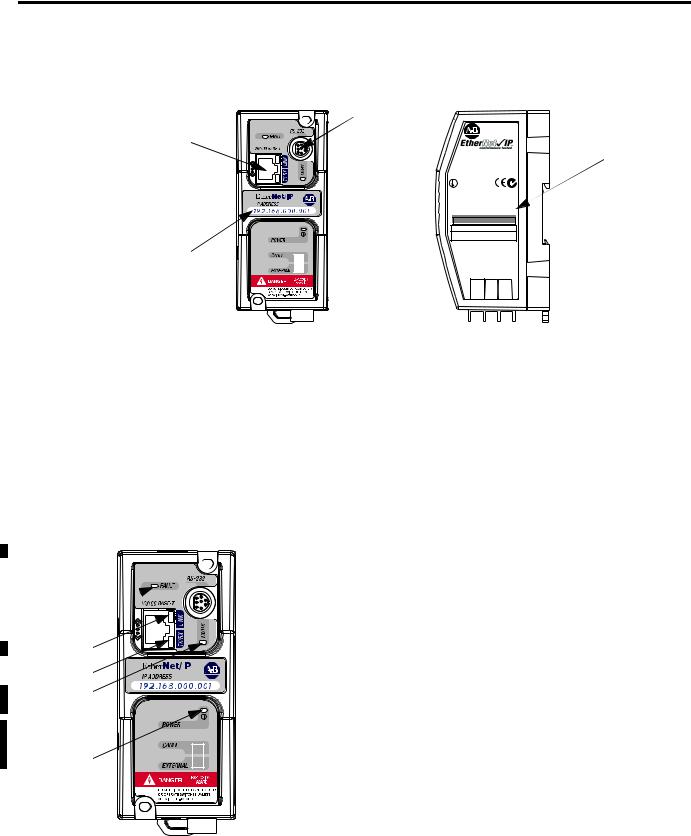
Hardware Features |
Product Drawing |
 RS-232
Mini-DIN Port
Ethernet Port
Series A/B: 10-Base-T
Series C/D: 10/100-Base-T
IP Address
Write-On Area
ETHERNET
INTERFACE
CAT |
SER FRN |
|
1761-NET-ENI |
B 2.20 |
|
E N I * B 2 2 0 0 1 0 2 0 0 0 1 |
|
|
|
F A C . x x |
|
|
|
|
|
LISTED IND.CONT.EQ. FOR HAZ. |
|
LOC. A196 |
C |
US OPERATING TEMPERATURE CODE T3C |
|
CLASS I, GROUPS A,B,C, AND D, DIV 2 N223 |
ETHERNET ADDRESS
F F -F F -F F -F F -F F -F F
EXTERNAL POWER REQUIREMENTS
24 V dc +10/-15% AT 100 mA N.E.C. CLASS 2
USE EXTERNAL DC SOURCE
FOR CLASS I DIVISION 2
APPLICATIONS. SEE
INSTALLATION INSTRUCTIONS
MADE IN U.S.A.
24VDC |
DC NEUT |
CHS GND |
 Ethernet Hardware
Address
Series A/B
FAULT 
LINK 
Ethernet TX/RX 
RS-232 TX/RX 
POWER 
LED Indicators
The ENI and ENIW have five LED indicators:
Table 1.1 Series A/B Descriptions
|
|
|
LED |
Description |
Function |
Color |
|
|
|
|
|
|
|
|
|
|
RS-232 |
RS-232 data |
flashes when the RS-232 port is |
green |
|
|
|
TX/RX |
transmission indicator |
transmitting or receiving data |
|
|
|
|
|
|
|
|
|
|
|
POWER |
module power |
lit when module is powered |
green |
|
|
|
|
|
|
|
|
|
|
LINK |
Ethernet link status |
lit when there is a valid physical |
green |
|
|
|
|
|
Ethernet connection |
|
|
|
|
|
|
|
|
|
|
|
Ethernet |
Ethernet data |
flashes when the Ethernet port is |
green |
|
|
|
TX/RX |
transmission indicator |
transmitting or receiving data |
|
|
|
|
|
|||
|
|
|
|
|
indicates Ethernet network traffic to |
|
|
|
|
|
|
and from the ENI/ENIW |
|
|
|
|
|
|
|
|
|
|
|
FAULT |
fault condition indicator |
lit when a fault condition is present |
red or |
|
|
|
|
|
|
flashing |
|
|
|
|
|
|
|
|
|
|
|
|
|
red |
|
|
|
|
|
|
|
|
|
|
|
|
|
|
Publication 1761-UM006E-EN-P - August 2005
Product Overview |
1-3 |
|
|
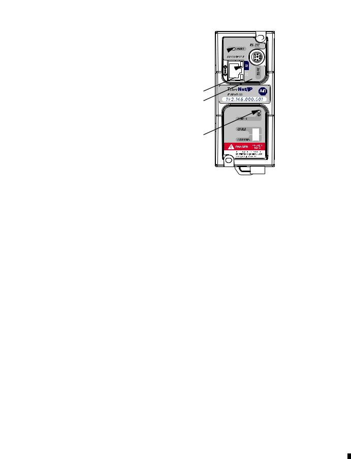
Series C
FAULT 
10 


100 
RS-232 TX/RX 
POWER 
Table 1.2 Series C Descriptions
LED |
Description |
Function |
Color |
|
|
|
|
|
|
|
|
RS-232 |
RS-232 data |
RS-232 port is transmitting or receiving |
flashing |
|
|
|
|
||||
TX/RX |
transmission indicator |
data |
green |
|
|
|
|
|
|
|
|
|
|
no RS-232 traffic |
off |
|
|
|
|
|
|
|
|
POWER |
module power |
module is powered |
green |
|
|
|
|
|
|
|
|
10 |
10-Base-T Ethernet |
No link or continuous data activity |
off |
|
|
|
|
||||
|
link status and data |
|
|
|
|
|
10-Base-T Half Duplex; Link good |
amber |
|
|
|
|
transmission indicator |
|
|
||
|
however no data activity |
|
|
|
|
|
|
|
|
|
|
|
|
|
|
|
|
|
|
10-Base-T Half Duplex; Link good with |
flashing |
|
|
|
|
sporadic data activity(1) |
amber |
|
|
|
|
10-Base- T Full Duplex; Link good |
green |
|
|
|
|
however no data activity |
|
|
|
|
|
|
|
|
|
|
|
10-Base-T Full Duplex; Link good with |
flashing |
|
|
|
|
sporadic data activity(1) |
green |
|
|
100 |
100-Base-T Ethernet |
No link or continuous data activity |
off |
|
|
|
link status and data |
|
|
|
|
|
100-Base-T Half duplex; Link good |
amber |
|
|
|
|
transmission indicator |
|
|
||
|
however no data activity |
|
|
|
|
|
|
|
|
|
|
|
|
|
|
|
|
|
|
100-Base-T Half Duplex; Link good |
flashing |
|
|
|
|
with sporadic data activity(1) |
amber |
|
|
|
|
100-Base-T Full Duplex; Link good |
green |
|
|
|
|
however no data activity |
|
|
|
|
|
|
|
|
|
|
|
100-Base-T Full Duplex; Link good with |
flashing |
|
|
|
|
sporadic data activity(1) |
green |
|
|
FAULT |
fault condition |
lit when a fault condition is present |
red or |
|
|
|
|
||||
|
indicator |
|
flashing red |
|
|
|
|
|
|
|
|
(1) Any Ethernet network activity; not necessarily to or from the ENI/ENIW.
Publication 1761-UM006E-EN-P - August 2005
1-4 Product Overview
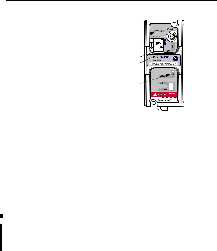
Series D
FAULT 
LINK 


Ethernet TX/RX 
RS-232 TX/RX 
POWER 
Table 1.3 Series D Descriptions
|
|
LED |
Description |
Function |
Color |
|
|
|
|
|
|
|
|
RS-232 |
RS-232 data |
RS-232 port is transmitting or |
flashing green |
|
|
transmission indicator |
receiving data |
|
|
|
|
TX/RX |
|
|
|
|
|
|
no RS-232 traffic |
off |
|
|
|
|
|
||
|
|
|
|
|
|
|
|
POWER |
module power |
module is powered |
green |
|
|
|
|
|
|
|
|
|
Ethernet link status and |
No link |
off |
|
|
|
|||
|
|
|
10-Base-T or |
|
|
|
|
LINK |
10-Base-T link |
amber |
|
|
|
100-Base-T indicator |
|||
|
|
|
|
|
|
|
|
|
|
100-Base-T link |
green |
|
|
|
|
|
|
|
|
|
Ethernet activity status |
No activity |
off |
|
|
|
|||
|
|
Ethernet |
and Half Duplex or Full |
|
|
|
|
Half Duplex activity(1) |
flashing amber |
||
|
|
Duplex status |
|||
|
|
TX/RX |
|
|
|
|
|
|
|
Full Duplex activity(1) |
flashing green |
|
|
|
|
||
|
|
|
|
|
|
|
|
FAULT |
fault condition |
lit when a fault condition is |
red or flashing |
|
|
||||
|
|
|
indicator |
present |
red |
|
|
|
|
|
|
(1) Any Ethernet network activity; not necessarily to or from the ENI/ENIW.
After out-of-box power-up, the most common reason for a flashing red fault LED is because an IP address has not yet been assigned via BOOTP. Either set up a BOOTP server to assign an IP address or modify the ENI/ENIW configuration to use a specific IP address or to obtain an IP address via a DHCP server.
For more detailed information on LED operation, see Chapter 9,
Troubleshooting.
Publication 1761-UM006E-EN-P - August 2005

Product Overview |
1-5 |
|
|
|
The IP addresses in any of the examples in this |
|
IMPORTANT |
||
manual were arbitrarily assigned and should only be |
||
|
||
|
||
|
used on an isolated Ethernet network. Contact your |
|
|
system administrator for unique IP addresses if you |
|
|
are connecting your Ethernet devices to your |
|
|
employer’s Ethernet network. |
|
|
|
Default Settings
The ENI/ENIW has the following default settings:
Table 1.4 RS-232 Settings
Setting |
Default |
Other Options |
|
|
|
|
|
Baud Rate |
Autobaud |
see table 4.2 |
|
|
|
|
|
Handshaking (hardware, software) |
none |
none |
|
|
|
|
|
Data Bits |
8 |
|
none |
|
|
|
|
Stop Bits |
1 |
|
none |
|
|
|
|
Parity |
none |
none |
|
|
|
|
|
Table 1.5 DF1 Settings |
|
|
|
|
|
|
|
Setting |
Default |
Other Options |
|
|
|
|
|
Duplicate Message Detection |
Enabled |
none |
|
|
|
|
|
Error Detection |
Auto-detect (for |
Auto-detect when |
|
|
Autobaud) |
Autobaud is true, |
|
|
|
|
otherwise CRC |
|
|
|
|
Embedded Response Operation |
Disabled(1) |
none |
|
DLE ACK Timeout |
1 second |
none |
|
|
|
|
|
DLE NAK Receive |
3 |
NAK retries |
none |
|
|
|
|
DLE ENQ for Response |
3 |
ENQs retries |
none |
|
|
|
|
DF1 Node Address |
Don’t Care |
|
|
|
|
|
|
(1) Connected controllers should be configured for Embedded Responses Disabled or Auto-detect.
Publication 1761-UM006E-EN-P - August 2005

1-6 Product Overview
Table 1.6 Ethernet Settings
|
|
Setting |
Default |
Other Options |
|
|
|
||||
|
|
|
|
|
|
|
|
Ethernet Speed/Duplex(1) |
10 Mbps half-duplex |
0 |
= Auto Negotiate |
|
|
||||
|
|
|
(series A, B) |
1 |
= 10 Mbps half-duplex |
|
|
|
Auto Negotiate (series C, D) |
2 |
= 10 Mbps full-duplex |
|
|
|
|
3 |
= 100 Mbps half-duplex |
|
|
|
|
4 |
= 100 Mbps full-duplex |
|
|
|
|
|
|
|
|
SMTP Username(1) |
null |
45 character username |
|
|
|
||||
|
|
|
|
|
|
|
|
SMTP Password(1) |
null |
45 character password |
|
|
|
||||
|
|
|
|
|
|
|
|
SMTP Authentication(1) |
Disabled |
0 |
= Disabled |
|
|
||||
|
|
|
|
1 |
= Enabled |
|
|
|
|
|
|
|
|
Configuration Security |
000.000.000.000 |
Valid IP address |
|
|
|
||||
|
|
Mask |
|
|
|
|
|
|
|
|
|
|
|
Save/Reset(2) |
n/a |
0 |
= save configuration to flash |
|
|
||||
|
|
|
|
1 |
= simple reset |
|
|
|
|
2 |
= reset to out-of-box defaults |
|
|
|
|
3 |
= reset to out-of-box, except |
|
|
|
|
maintain current IP |
|
|
|
|
|
configuration |
|
|
|
|
|
|
|
|
|
From String |
ENI192.168.1.254@eni1761. |
ENI/ENIW Identifier |
|
|
|
||||
|
|
|
org(4) |
|
|
|
|
|
|
|
|
|
|
IP Address |
000.000.000.000 |
valid IP Address |
|
|
|
||||
|
|
|
192.168.1.254(1) |
|
|
|
|
|
|
|
|
|
|
Subnet Mask |
0.0.0.0(5) |
valid subnet mask |
|
|
|
||||
|
|
|
|
|
|
|
|
Gateway Address |
0.0.0.0 |
valid IP address |
|
|
|
||||
|
|
|
|
|
|
|
|
Security Mask 1 |
0.0.0.0 |
valid IP address |
|
|
|
||||
|
|
|
|
|
|
|
|
Security Mask 2 |
0.0.0.0 |
valid IP address |
|
|
|
||||
|
|
|
|
|
|
|
|
Email Server |
000.000.000.000 |
valid IP address |
|
|
|
||||
|
|
|
|
|
|
|
|
BOOTP Configuration |
0 |
0 |
= BOOTP initially |
|
|
||||
|
|
|
|
1 |
= BOOTP/DHCP disabled |
|
|
|
|
2 |
= BOOTP fallback(6) |
|
|
|
|
3 |
= BOOTP always(6) |
|
|
|
|
4 |
= DHCP always(6) |
|
|
|
|
|
|
|
|
Baud Rate(3) |
See page 4-14. |
Autobaud enabled with |
|
|
|
||||
|
|
|
|
autodetect of CRC/BCC |
|
|
|
|
|
|
|
|
|
Ethernet Hardware |
Factory Value - Read Only |
Factory Value |
|
|
|
||||
|
|
Address |
(see the nameplate on the |
|
|
|
|
|
unit) |
|
|
|
|
|
|
|
|
(1)Series D only.
(2)See page 4-19.
(3)Changes to the Baud Rate take effect when the ENI/ENIW power is cycled, or the configuration is saved to flash.
(4)TThe ENI/ENIW address, 192.168.1.254 will be replaced by the IP address assigned to the ENI/ENIW. For example, the string may be ENI191.225.181.52@eni1761.org. If the ENI/ENIW does not have an assigned IP address, the string will be read as ENI192.168.1.254@eni1761.org for the series D or ENI0.0.0.0@eni1761.org for series A, B, or C.
(5)See page 4-17 for Subnet Mask auto-detect mode details.
(6)Series C and higher.
Publication 1761-UM006E-EN-P - August 2005

Product Overview |
1-7 |
|
|
Operating Modes
Messaging
When the ENI/ENIW is connected to a programmable controller (and connected to an Ethernet network), the controller can be accessed from other devices on Ethernet, or initiate communications to other EtherNet/IP devices.
Device Compatibility
Series B Enhancements
The ENI/ENIW also support SMTP mail service, which allows a controller to send email messages to any email address on the network. The email can be used to initiate the transmission of data or status information.
The ENI/ENIW are compatible with the following devices and applications:
•All MicroLogix, SLC, PLC-5, CompactLogix, FlexLogix, and ControlLogix controllers, which support DF1 Full-Duplex on an available RS-232 port
•Personal Computers using the RSLinx (V2.30.00 and higher) DF1 Full-Duplex Driver
•Other DF1 Full-Duplex compliant products that have at least one RS-232 port, for example, operator interface devices
•RSLinx (V2.31.00 and higher) Ethernet Driver
The 1761-NET-ENI series B features the following enhancements:
•elimination of the need for two ENIs in a CompactLogix, FlexLogix, or ControlLogix system using RSLogix 5000
•ability to use Dynamic Host Configuration Protocol (DHCP)
•two new BOOTP options
The 1761-NET-ENIW has the same features as the 1761-NET-ENI, but includes web-serving capabilities as discussed on page 1-9.
Publication 1761-UM006E-EN-P - August 2005
1-8 Product Overview
Series C Enhancements
Series D Enhancements
The 1761-NET-ENI/ENIW series C features the following enhancements:
•10/100-Base-T Ethernet port that auto-negotiates between 10 Megabits per second and 100 Megabits per second, either half-duplex or full-duplex.
•increased temperature range up to 60°C (140°F)
•increased messaging performance
The ENI/ENIW series D features the following enhancements:
•Ability to configure the ENI/ENIW over Ethernet
•Email user authentication for open mail servers
•Ability to force 10 Mbps or 100 Mbps and half-duplex or full-duplex Ethernet configuration
•Diagnostic web-page for Ethernet connections in use
•Revised web-page formats for ENIW
Ethernet Networks
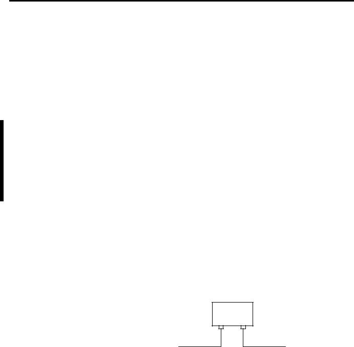
Basic Ethernet Topology
The ENI/ENIW Ethernet connectors conform to ISO/IEC 8802-3 STD 802.3 and utilizes 10/100 Base-T media. Connections are made directly from the ENI/ENIW to an Ethernet switch. The network setup is simple and cost effective. Typical network topology is pictured below.
Ethernet
Switch
to PC Ethernet Card or other Ethernet Device
RJ45 connectors on both ends of cable (10/100 Base-T)
to ENI or ENIW
Publication 1761-UM006E-EN-P - August 2005
Product Overview |
1-9 |
|
|
IMPORTANT |
The ENI/ENIW provides a 10/100 Base-T, RJ45 |
|
Ethernet connector which connects to standard |
||
|
||
|
||
|
Ethernet hubs and switches via an 8-wire twisted |
|
|
pair straight-through cable. To access other Ethernet |
|
|
mediums, use 10/100 Base-T media converters or |
|
|
Ethernet switches that can be connected together via |
|
|
fiber, thin-wire, or thick-wire coaxial cables, or any |
|
|
other physical media commercially available with |
|
|
Ethernet switches. See page 2-6 for more cable |
|
|
information. |
|
|
|
Web Server Functionality |
The ENIW enhances operation with web server functionality, enabling |
|
|
it to: |
|
|
• display 40 data table values on 4 standard Data View web pages |
|
|
|
|
|
consisting of 7 integer and 3 floating-point values on each page, |
|
|
• display 10 user-configurable data description strings on each |
|
|
Data View web page, |
|
|
• display a diagnostic page with status and IP Address of active |
|
|
|
|
|
Ethernet connections (series D only), |
|
|
• password protect writable data files to prevent unauthorized |
|
|
modification, and |
|
|
• provide 10 user-configurable web page links. |
|
|
You can access information about the ENI/ENIW via your web |
|
|
browser. Simply enter it’s TCP/IP address into the address field of |
|
|
your browser. |
|
|
See Chapter 7 for details on using the ENIW’s web server capabilities. |
|
Publication 1761-UM006E-EN-P - August 2005

1-10 Product Overview
Publication 1761-UM006E-EN-P - August 2005

Chapter 2
Installation and Wiring
European Communities (EC)
Directive Compliance
This chapter covers installation and wiring for the ENI/ENIW. It is divided into the following sections:
•European Communities (EC) Directive Compliance
•Safety Considerations
•Mounting
•External Power Supply Wiring
•ENI/ENIW Port Identification
•Ethernet Connections
•RS-232 Port Connections
This product has the CE mark. It is approved for installation within the European Union and EEA regions. It has been designed and tested to meet the following directives.
EMC Directive
This product is tested to meet the Council Directive 89/336/EC Electromagnetic Compatibility (EMC) by applying the following standards, in whole or in part, documented in a technical construction file:
•EN 50081-2 EMC — Generic Emission Standard, Part 2 — Industrial Environment
•EN 50082-2 EMC — Generic Immunity Standard, Part 2 — Industrial Environment
This product is intended for use in an industrial environment.
Low Voltage Directive
This product is tested to meet Council Directive 73/23/EEC Low Voltage, by applying the safety requirements of EN 61131-2 Programmable Controllers, Part 2 - Equipment Requirements and
Publication 1761-UM006E-EN-P - August 2005

2-2 Installation and Wiring
Safety Considerations
Tests. For specific information required by EN 61131-2, see the appropriate sections in this publication, as well as the Allen-Bradley publication Industrial Automation Wiring and Grounding Guidelines For Noise Immunity, publication 1770-4.1.
Open style devices must be provided with environmental and safety protection by proper mounting in enclosures designed for specific application conditions. See NEMA Standards publication 250 and IEC publication 529, as applicable, for explanations of the degrees of protection provided by different types of enclosure.
This equipment is suitable for use in Class I, Division 2, Groups A, B, C, D, or non-hazardous locations only. The following WARNING statement applies to use in hazardous locations.
Explosion Hazard
WARNING
• Substitution of components may impair suitability for Class I, Division 2.
• Do not replace components or disconnect equipment unless power has been switched off and the area is known to be non-hazardous.
•Do not connect or disconnect connectors or operate switches while circuit is live unless the area is known to be non-hazardous.
•This product must be installed in an enclosure. All cables connected to the product must remain in the enclosure or be protected by conduit or other means.
•The ENI/ENIW must be operated using the external power source. The DC power source switch must be in the EXTERNAL position.
•All wiring must comply with N.E.C. article 501-4(b).
Use only the following communication cables and replacement connectors in Class I Division 2 Hazardous Locations.
Environment Classification |
Communication Cable and Connectors |
||
|
|
|
|
Class I, Division 2 Hazardous |
1761-CBL-PM02 Series C |
2707-NC8 Series B |
|
Environment |
|
|
|
1761-CBL-HM02 Series C |
2707-NC9 Series B |
||
|
|||
|
|
|
|
|
1761-CBL-AM00 Series C |
2707-NC10 Series B |
|
|
|
|
|
|
1761-CBL-AP00 Series C |
2707-NC11 Series B |
|
|
|
|
|
Publication 1761-UM006E-EN-P - August 2005
Installation and Wiring |
2-3 |
|
|
External Power Supply
Wiring
EXPLOSION HAZARD
WARNING
In Class I Division 2 applications, an external, Class 2 power supply must be used. The DC Power Source selector switch on the ENI/ENIW must be set to EXTERNAL before connecting the power supply to the ENI/ENIW.
IMPORTANT
24 VDC
DC
NEUT
CHS
GND
Bottom View
•In non-hazardous locations, external power is not required. Some devices (such as a MicroLogix controller) provide power to the ENI/ENIW via a cable connected to the ENI/ENIW’s port 2. Be sure to set the DC power source selector switch to match your particular configuration, CABLE or EXTERNAL.
•Always connect the CHS GND (chassis ground) terminal to the nearest earth ground. This connection must be made whether or not an external 24V dc supply is used.
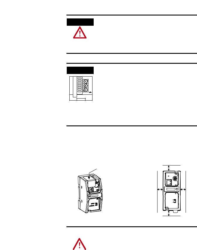
Mounting
The ENI/ENIW must be mounted in the vertical position, as shown.
Horizontal mounting is not recommended due to thermal considerations. Allow 50 mm (2 in.) of space on all sides for adequate ventilation. See page A-1 for operating temperature specification.
protective debris strip |
top |
|
|
|
|
|
ETHERNET |
|
|
RS232 |
|
|
FAULT |
|
|
TX/RX |
|
side |
IP |
side |
|
PWR |
|
|
CABLE |
|
|
EXTERNAL |
|
|
bottom |
|
ATTENTION |
Do not remove the protective debris strip until after |
|||
all the equipment in the panel is mounted and wiring |
||||
|
|
|
||
|
|
|
||
|
|
|
is complete. Once wiring is complete, remove the |
|
|
|
|
protective debris strip. Failure to remove strip before |
|
|
|
|
operating can cause overheating. |
|
|
|
|
|
|
Publication 1761-UM006E-EN-P - August 2005
2-4 Installation and Wiring
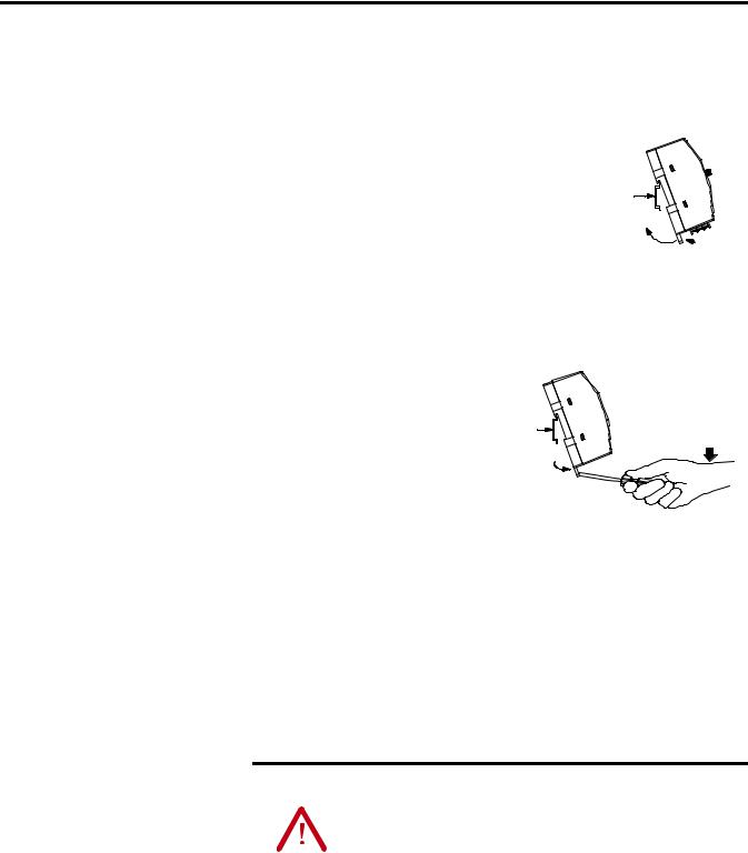
DIN Rail Mounting
Installation
1.Mount your DIN rail.
2.Snap the DIN rail latch into the closed position.
3.Hook the top slot over the DIN rail.
4.While pressing the unit against the rail, snap the unit into position.
DIN
Rail
 Latch
Latch
Removal
1.Place a screwdriver in the DIN rail latch at the bottom
of the unit. |
DIN |
|
Rail |
2.Holding the unit, pry downward on the latch until the unit is released from the DIN rail.
Side
View
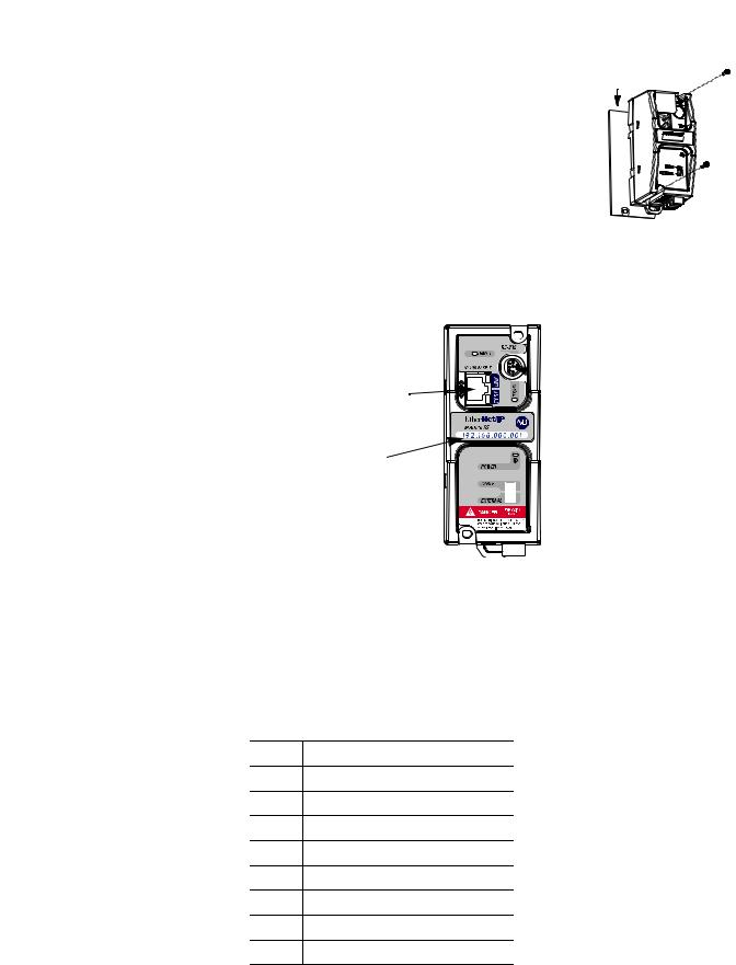
Panel Mounting
Template
See Appendix A for panel mounting dimensions.
Installation
ATTENTION |
Be careful of metal chips when drilling mounting |
|||
holes for your equipment within the enclosure or |
||||
|
|
|
||
|
|
|
||
|
|
|
panel. Drilled fragments that fall into the equipment |
|
|
|
|
could cause damage. Do not drill holes above |
|
|
|
|
mounted equipment if the protective debris strip has |
|
|
|
|
been removed. |
|
|
|
|
|
|
Publication 1761-UM006E-EN-P - August 2005
Installation and Wiring |
2-5 |
|
|
1. Remove the mounting template from
the back of the installation instructions. Mounting Template
2. Secure the template to the mounting surface.
3.Drill holes through the template.
4.Remove the mounting template.
5.Mount the unit.
ENI/ENIW Port
Identification
RS-232 Mini-DIN (Port 2)
Ethernet Port (Port 1)
Write-on area for
Ethernet IP address
Ethernet Connections
Ethernet 8-Pin 10/100-Base-T Connector (Port 1)
The Ethernet connector is an RJ45, 10/100-Base-T connector. The pin-out for the connector is shown below:
Pin |
Pin Name |
1Tx+
2Tx-
3Rx+
4not used
5not used
6Rx-
7not used
8not used
Publication 1761-UM006E-EN-P - August 2005

2-6 Installation and Wiring
When to use straight-through and cross-over cables:
•ENI/ENIW Ethernet port to 10/100-Base-T Ethernet switch cables utilize a straight-through pin-out (1-1, 2-2, 3-3, 6-6).
•Direct point-to-point 10/100-Base-T cables connecting the ENI/ENIW Ethernet port directly to another ENI/ENIW Ethernet port (or a computer 10/100-Base-T port) require a cross-over pin-out (1-3, 2-6, 3-1, 6-2).
Ethernet Cables
Shielded and non-shielded twisted-pair 10/100-Base-T cables with RJ45 connectors are supported. The maximum cable length between an ENI/ENIW Ethernet port and a 10/100-Base-T port on an Ethernet switch (without repeaters or fiber) is 100 meters (323 feet). However, in an industrial application, the cable length should be kept to a minimum.
With media converters or Ethernet switches, you can also connect to the following media:
•fiber optic
•broadband
•thick-wire coaxial cable (10-Base-5)
•thin-wire coaxial cable (10-Base-2)
Maintain ENI and ENIW Cable Connections
The unshielded twisted pair (UTP) patch cable on a switch should be labeled and treated as dedicated. Be careful when moving any cables, as port identity may be effected. If you are using a switch and must move the ENI/ENIW to a new port for any reason, power-cycle the interface. The power cycle forces a new Address Resolution Protocol (ARP) sequence which should immediately associate the ENI/ENIW’s IP address with the port it is connected to.
To help prevent problems with network communications affected by moving cables, discourage any field personnel from treating the ports of a switch as “all the same”.
Publication 1761-UM006E-EN-P - August 2005

Installation and Wiring |
2-7 |
|
|
RS-232 Port Connections |
RS-232 Connector |
|
|
|
7 |
|
6 |
8 |
|
8-pin mini-DIN |
3 |
|
5 |
|
|
4 |
|
2 |
1 |
|
Table 2.1 RS-232 Connector Pin Assignments
Pin |
Port 2 |
124V dc
2ground (GND)
3no connection
4ENI/ENIW input data, RxD
5no connection
6no connection
7ENI/ENIW output data, TxD
8ground (GND)
RS-232 Cables
Port 2 of the ENI/ENIW is an 8-pin mini-DIN RS-232 port that provides connection to DF1 compatible RS-232 devices. The table below describes the RS-232 compatible cables.
ENI/ENIW Connected to: |
Catalog Number |
Use Cable |
|
|
|
|
|
|
|
MicroLogix 1000, 1100, 1200, and |
|
Mini DIN to Mini DIN |
|
|
|
|
|
||
1500, Channel 0 (all series) |
1761-CBL-AM00 |
45 cm (17.7 in) |
|
|
|
1761-CBL-HM02 |
2m (6.5 ft.) |
|
|
|
|
|
|
|
SLC 5/03, SLC 5/04, or |
|
Mini DIN to D-Shell |
|
|
SLC 5/05, Channel 0 |
1761-CBL-AP00 |
45 cm (17.7 in) |
|
|
MicroLogix 1500 LRP, Channel 1 |
1761-CBL-PM02 |
2m (6.5 ft.) |
|
|
CompactLogix, FlexLogix, or |
|
|
|
|
ControlLogix serial ports |
|
|
|
|
|
|
|
|
|
See page 2-2 for the list of cables that can be used in a hazardous environment.
Publication 1761-UM006E-EN-P - August 2005

2-8 Installation and Wiring
Publication 1761-UM006E-EN-P - August 2005
Loading...