


1738-AENT
Table of contents
 Loading...
User Manual
1738 ArmorPOINT I/O EtherNet/IP Adapters
Catalog Numbers
1738-AENT, Series B
Important User Information
Solid-state equipment has operational characteristics differing from those of electromechanical equipment. Safety
Guidelines for the Application, Installation and Maintenance of Solid State Controls (publication SGI-1.1
available from
your local Rockwell Automation sales office or online at http://www.rockwellautomation.com/literature/
) describes some
important differences between solid-state equipment and hard-wired electromechanical devices. Because of this difference,
and also because of the wide variety of uses for solid-state equipment, all persons responsible for applying this equipment
must satisfy themselves that each intended application of this equipment is acceptable.
In no event will Rockwell Automation, Inc. be responsible or liable for indirect or consequential damages resulting from
the use or application of this equipment.
The examples and diagrams in this manual are included solely for illustrative purposes. Because of the many variables and
requirements associated with any particular installation, Rockwell Automation, Inc. cannot assume responsibility or
liability for actual use based on the examples and diagrams.
No patent liability is assumed by Rockwell Automation, Inc. with respect to use of information, circuits, equipment, or
software described in this manual.
Reproduction of the contents of this manual, in whole or in part, without written permission of Rockwell Automation,
Inc., is prohibited.
Throughout this manual, when necessary, we use notes to make you aware of safety considerations.
Allen-Bradle y, Rockwell Software, Rockwell Automation, ArmorPOINT I/O, ControlLogix, RSLogix, RSLinx, and TechConnect are trademarks of Rockwell Automation, Inc.
Trademarks not belonging to Rockwell Automation are property of their respective companies.
WARNING: Identifies information about practices or circumstances that can cause an explosion in a hazardous
environment, which may lead to personal injury or death, property damage, or economic loss.
ATTENTION: Identifies information about practices or circumstances that can lead to personal injury or death,
property damage, or economic loss. Attentions help you identify a hazard, avoid a hazard, and recognize the
consequence
SHOCK HAZARD: Labels may be on or inside the equipment, for example, a drive or motor, to alert people that
dangerous voltage may be present.
BURN HAZARD: Labels may be on or inside the equipment, for example, a drive or motor, to alert people that
surfaces may reach dangerous temperatures.
IMPORTANT
Identifies information that is critical for successful application and understanding of the product.

Rockwell Automation Publication 1738-UM005A-EN-P - July 2013 i
Preface
Read this preface to familiarize yourself with the rest of the manual. It provides
information concerning:
• who should use this manual
• the purpose of this manual
• related documentation
• conventions used in this manual
Who Should Use this
Manual
This manual is intended for control engineers and technicians who are installing,
configuring, maintaining, and troubleshooting an EtherNet/IP control system
that communicates with ArmorPOINT I/O
®
through a 1738-AENT Series B
adapter. You must be able to use RSLogix
®
5000 software to configure your
adapter.
Purpose of This Manual
This manual contains an overview of the ArmorPOINT I/O adapter. It
describes how to install and configure the adapter and provides examples
showing how to use the adapter to communicate with ArmorPOINT I/O
modules over an EtherNet/IP network.
Related Documentation
The following documents contain additional information concerning Rockwell
Automation products. To obtain a copy, contact your local Rockwell Automation
office or distributor.
Resource Description
1738 ArmorPOINT I/O Selection Guide, publication 1738-SG001
A description and overview of the 1738 series adapters, I/O modules, and
compatible control platforms.
EtherNet/IP Performance and Application Guide, publication
ENET-RM002
.
Using EtherNet/IP for Industrial Control.
EtherNet/IP Modules in Logix5000
™ Control Systems User
Manual, publication ENET-UM001
A manual describing how to use EtherNet/IP modules with Logix5000
controllers and communicate with various devices on the Ethernet network.
ControlLogix
®
Chassis and Power Supplies Installation
Instructions, publication 1756-IN005.
Describes how to install and troubleshoot standard and ControlLogix-XT
versions of the 1756 chassis and power supplies, including redundant power
supplies.
ControlLogix
EtherNet/IP Bridge Module Installation Instructions,
publication 1756-IN019
ControlLogix EtherNet/IP Bridge Module installation instructions.
ControlLogix
System User Manual, publication 1756-UM001 Detailed information on how to install, configure and troubleshoot the
ControlLogix Sequence of Events module in your ControlLogix application.
RSLinx
®
Classic Getting Results Guide, publication LINX-GR001 Information on how to install and navigate the RSLinx Classic software. It
explains how to access and navigate the help, and how to effectively use the
RSLinx Classic software.
1738 ArmorPOINT I/O
®
EtherNet/IP Adapter Installation
Instructions, publication 1738-IN030
Installation instructions for installing the 1738 POINT I/O EtherNet/IP Adapter.
Pinout Guide for 1738 ArmorPOINT Adapters and Power Supplies
Wiring Diagram, publication 1738-WD011
Information on wiring 1738 ArmorPOINT I/O EtherNet/IP Series B Adapters and
Power Supplies.

ii Rockwell Automation Publication 1738-UM005A-EN-P - July 2013
EtherNet/IP Embedded Switch Technology Application Guide,
publication ENET-AP005
An application guide describing how to install, configure and maintain linear
and Device-level Ring (DLR) networks using Rockwell Automation EtherNet/IP
devices with embedded switch technology.
Allen-Bradley Industrial Automation Glossary, publication
AG-QR071
A glossary of industrial automation terms and abbreviations.
Industrial Automation Wiring and Grounding Guidelines,
publication 1770-IN041
.
Detailed information on proper wiring and grounding techniques.
EtherNet/IP Media Planning and Installation Manual (ODVA)
. Installing an EtherNet/IP network
Resource Description
TIP
Many of these publications are available online from:
http://literature.rockwellautomation.com/
Rockwell Automation Publication 1738-UM005A-EN-P - July 2013 iii
Common Techniques Used
in this Manual
The following conventions are used throughout this manual:
• Bulleted lists such as this one provide information, not procedural steps.
• Numbered lists provide sequential steps or hierarchical information.
• Italic type is used for emphasis.
Rockwell Software products contain extensive tutorials and help screens. We
recommend that you use these tutorials and help screens to learn about the
products.
For more information about Rockwell Software products, visit the Rockwell
Software website at
http://www.rockwellautomation.com/software/.
About the Example Applications
This manual presents two example applications that demonstrate the procedures
for configuring and communicating with ArmorPOINT I/O modules using the
ArmorPOINT I/O adapter. We intend the example applications as building
blocks to help you get your own system up and running. We recommend that you
set up and run the example applications and use them as guides.
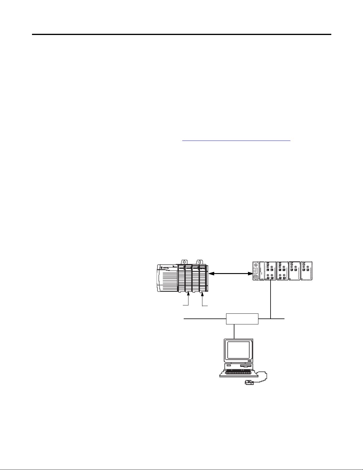
Here is the type of system you’ll be setting up.
0
0
1
2
3
1
MOD
NET
1738-OB4EM12
24V dc Out
1738-AENT
Adapter
Status
Network
Activity
PointBus
Status
System
Power
Adapter
Power
EtherNet I/P
PWR
x1
x10
6
0
8
2
4
6
0
8
2
4
0
0
2
1
2
3
1
3
MOD
NET
1738-IB4M12
24V dc In
I
x100
6
0
8
2
4
Network
Status
conformance tested
™
P
A
E
D
D
R
S
S
0
02
1
MOD
NET
1738-OE2CM12
Analog Current Out
0
0
1
1
MOD
NET
1738-IE2CM12
Analog Current In
2
3
Local
Chassis
ArmorPOINT I/O
L63
Controller (slot 1)
1756-ENBT
10.88.70.90 (slot 3)
Data
Switch
10.88.70.26
1738-AENT/B 10.88.70.2
31393-M
Programming
Ter mi na l
Slot 0 1 2 3

iv Rockwell Automation Publication 1738-UM005A-EN-P - July 2013
System Components
We used the following components for the example applications. You will need
the same or similar components to set up your own control system using
ArmorPoint I/O on EtherNet/IP.
System Components
Quantity Product Name Catalog Number
Hardware
1 ArmorPoint I/O EtherNet/IP Adapter 1738-AENT
1 ArmorPoint 24V DC Input Module 1738-IB4M12
ArmorPoint I/O 24V DC Sink Output Module 1738-OB4EM12
1 ArmorPoint I/O Analog Input Current Module 1738-IE2CM12
1 ArmorPoint I/O Analog Output Current Module 1738-OE2CM12
1 DIN Rail 199-DR1 or equivalent
1 ControlLogix chassis 1756-A4, (or 1756-A7,
1756-A13, 1756-A17)
1 ControlLogix power supply 1756-PA72, (or 1756-PB72)
1 L63 Controller 1756-L63
1 ControlLogix EtherNet/IP Bridge Module 1756-ENBT
1 Personal computer that supports RSLogix 5000
software
Any appropriate model running
Windows NT, Windows 2000,
Windows XP or higher
Any appropriate model running
Windows
NT 4.0, Service Pack 6A or
higher
1 Ethernet switch Refer to manufacturer’s
specifications
1 24V DC power supply 1738-EP24DC
Associated media and connectors as needed
Software
1 RSLinx communications software,
V2.56 or later.
9355-WAB, 9355-WABOEM,
9355-WABC
1 RSLogix 5000 programming software,
V17 or higher
9324-RLD300ENE

Rockwell Automation Publication 1738-UM005A-EN-P - July 2013 v
Table of Contents
Preface
Who Should Use this Manual . . . . . . . . . . . . . . . . . . . . . . . . . . . . . . . . . . . . . . . i
Purpose of This Manual . . . . . . . . . . . . . . . . . . . . . . . . . . . . . . . . . . . . . . . . . . . . i
Related Documentation. . . . . . . . . . . . . . . . . . . . . . . . . . . . . . . . . . . . . . . . . i
Additional Resources . . . . . . . . . . . . . . . . . . . . . . . . . . . . . . . . . . . . . . . . . . . . . . ii
Terminology. . . . . . . . . . . . . . . . . . . . . . . . . . . . . . . . . . . . . . . . . . . . . . . . . . . . . . . v
Common Techniques Used in this Manual. . . . . . . . . . . . . . . . . . . . . . . . . viii
About the Example Applications. . . . . . . . . . . . . . . . . . . . . . . . . . . . . . . viii
System Components. . . . . . . . . . . . . . . . . . . . . . . . . . . . . . . . . . . . . . . . . . . ix
Chapter 1
Overview of the 1738
ArmorPOINT I/O EtherNet/IP
Adapter
Overview . . . . . . . . . . . . . . . . . . . . . . . . . . . . . . . . . . . . . . . . . . . . . . . . . . . . . . . . . . 1
Adapter Features . . . . . . . . . . . . . . . . . . . . . . . . . . . . . . . . . . . . . . . . . . . . . . . . . . . 1
What the Adapter Does . . . . . . . . . . . . . . . . . . . . . . . . . . . . . . . . . . . . . . . . . . . . 2
Physical Features of Your Adapter . . . . . . . . . . . . . . . . . . . . . . . . . . . . . . . . . . . 3
Hardware/Software Compatibility . . . . . . . . . . . . . . . . . . . . . . . . . . . . . . . . . . 3
Important Adapter Considerations . . . . . . . . . . . . . . . . . . . . . . . . . . . . . . . . . . 4
Set the Chassis Size . . . . . . . . . . . . . . . . . . . . . . . . . . . . . . . . . . . . . . . . . . . . . 4
Adapter Replacement . . . . . . . . . . . . . . . . . . . . . . . . . . . . . . . . . . . . . . . . . . . 4
Empty Slots and RIUP Situations. . . . . . . . . . . . . . . . . . . . . . . . . . . . . . . . 5
Power Up a System for the First Time . . . . . . . . . . . . . . . . . . . . . . . . . . . . 6
Use of the Common Industrial Protocol (CIP) . . . . . . . . . . . . . . . . . . . . . . . 6
Understand the Producer/Consumer Model . . . . . . . . . . . . . . . . . . . . . . . . . 6
Specify the Requested Packet Interval (RPI) . . . . . . . . . . . . . . . . . . . . . . . . . . 7
Support for Rack-optimized and Direct Connections . . . . . . . . . . . . . . . . . 7
Mixing Rack-optimized and Direct Connections. . . . . . . . . . . . . . . . . . 8
Chapter Summary. . . . . . . . . . . . . . . . . . . . . . . . . . . . . . . . . . . . . . . . . . . . . . . . . . 8
Chapter 2
Install Your ArmorPOINT I/O
Adapter
Overview . . . . . . . . . . . . . . . . . . . . . . . . . . . . . . . . . . . . . . . . . . . . . . . . . . . . . . . . . . 1
Mount the Adapter and I/O Base. . . . . . . . . . . . . . . . . . . . . . . . . . . . . . . . . . . . 2
Install the ArmorPOINT I/O Modules . . . . . . . . . . . . . . . . . . . . . . . . . . 3
Remove an ArmorPoint I/O Module. . . . . . . . . . . . . . . . . . . . . . . . . . . . . 3
Wire the Adapter . . . . . . . . . . . . . . . . . . . . . . . . . . . . . . . . . . . . . . . . . . . . . . . . . . 4
Wire an ArmorPOINT I/O Adapter. . . . . . . . . . . . . . . . . . . . . . . . . . . . . 4
Chapter Summary. . . . . . . . . . . . . . . . . . . . . . . . . . . . . . . . . . . . . . . . . . . . . . . . . . 4

vi Rockwell Automation Publication 1738-UM005A-EN-P - July 2013
Table of Contents
Chapter 3
Configure the Adapter with
RSLogix5000 software
Introduction . . . . . . . . . . . . . . . . . . . . . . . . . . . . . . . . . . . . . . . . . . . . . . . . . . . . . . 1
Configuration Requirements . . . . . . . . . . . . . . . . . . . . . . . . . . . . . . . . . . . . . . . 2
IP Address . . . . . . . . . . . . . . . . . . . . . . . . . . . . . . . . . . . . . . . . . . . . . . . . . . . . 2
Gateway Address . . . . . . . . . . . . . . . . . . . . . . . . . . . . . . . . . . . . . . . . . . . . . . 3
Subnet Mask . . . . . . . . . . . . . . . . . . . . . . . . . . . . . . . . . . . . . . . . . . . . . . . . . . 4
Set the Network Address. . . . . . . . . . . . . . . . . . . . . . . . . . . . . . . . . . . . . . . . . . . 5
Set the Network Address for ArmorPOINT I/O Adapters . . . . . . . . 5
Use the Rockwell BootP/DHCP Utility. . . . . . . . . . . . . . . . . . . . . . . . . . . . . 6
Save the Relation List . . . . . . . . . . . . . . . . . . . . . . . . . . . . . . . . . . . . . . . . . . 9
Use DHCP Software to Configure Your Adapter . . . . . . . . . . . . . . . . . . . 10
Chapter Summary . . . . . . . . . . . . . . . . . . . . . . . . . . . . . . . . . . . . . . . . . . . . . . . . 10
Chapter 4
Configure the Adapter for Direct
Connection in RSLogix 5000
Software
Overview . . . . . . . . . . . . . . . . . . . . . . . . . . . . . . . . . . . . . . . . . . . . . . . . . . . . . . . . 11
Set Up the Hardware . . . . . . . . . . . . . . . . . . . . . . . . . . . . . . . . . . . . . . . . . . . . . 12
Create the Example Application . . . . . . . . . . . . . . . . . . . . . . . . . . . . . . . . . . . 13
Configure the I/O. . . . . . . . . . . . . . . . . . . . . . . . . . . . . . . . . . . . . . . . . . . . . . . . 14
Add the Local EtherNet/IP Bridge to the I/O Configuration. . . . . 14
Add the ArmorPOINT I/O Adapter to the I/O Configuration . . 16
Add the ArmorPoint I/O Modules to the I/O Configuration . . . . 19
Add the Digital Input Module 20
Add the Digital Output Module 23
Add the Analog Current Input Module 25
Add the Analog Current Output Module 28
Edit the Controller Tags . . . . . . . . . . . . . . . . . . . . . . . . . . . . . . . . . . . . . . . . . . 31
Create the Ladder Program. . . . . . . . . . . . . . . . . . . . . . . . . . . . . . . . . . . . . . . . 32
Download the Program to the Controller. . . . . . . . . . . . . . . . . . . . . . . . . . . 33
Verify the Module
Chassis Size . . . . . . . . . . . . . . . . . . . . . . . . . . . . . . . . . . . . . . . . . . . . . . . . . . . . . . 34
Configure the 1738-AENT/B Adapter with a
Fixed IP Address . . . . . . . . . . . . . . . . . . . . . . . . . . . . . . . . . . . . . . . . . . . . . . . . . 37
Chapter Summary . . . . . . . . . . . . . . . . . . . . . . . . . . . . . . . . . . . . . . . . . . . . . . . . 37

Rockwell Automation Publication 1738-UM005A-EN-P - July 2013 vii
Table of Contents
Chapter 5
Configure the Adapter for Direct
Connection and Rack
Optimization in RSLogix 5000
Software
Overview . . . . . . . . . . . . . . . . . . . . . . . . . . . . . . . . . . . . . . . . . . . . . . . . . . . . . . . . 39
Set Up the Hardware . . . . . . . . . . . . . . . . . . . . . . . . . . . . . . . . . . . . . . . . . . . . . 40
Set Up the ArmorPOINT I/O Hardware . . . . . . . . . . . . . . . . . . . . . . 40
Create the Example Application . . . . . . . . . . . . . . . . . . . . . . . . . . . . . . . . . . . 41
Configure the I/O Modules. . . . . . . . . . . . . . . . . . . . . . . . . . . . . . . . . . . . . . . 42
Add the Local EtherNet/IP Bridge to the I/O Configuration . . . . 42
Add the ArmorPOINT I/O Adapter to the I/O Configuration . . 44
Add the ArmorPoint Digital Modules and Configure For Rack
Optimization Connection . . . . . . . . . . . . . . . . . . . . . . . . . . . . . . . . . . . . 48
Add the Digital Input Module 48
Add The Digital Output Module 50
Add the ArmorPoint Analog Modules and Configure For Direct
Connection . . . . . . . . . . . . . . . . . . . . . . . . . . . . . . . . . . . . . . . . . . . . . . . . . . 52
Add the Analog Current Input Module 52
Add the Analog Current Output Module 54
Download the Program to the Controller . . . . . . . . . . . . . . . . . . . . . . . . . . 57
Verify the Module
Chassis Size. . . . . . . . . . . . . . . . . . . . . . . . . . . . . . . . . . . . . . . . . . . . . . . . . . . . . . 58
An Overloaded
1738-AENT/B Adapter . . . . . . . . . . . . . . . . . . . . . . . . . . . . . . . . . . . . . . . . . . 60
Access Module Data via the 1738-AENT/B Adapter. . . . . . . . . . . . . . . . 61
Chapter Summary. . . . . . . . . . . . . . . . . . . . . . . . . . . . . . . . . . . . . . . . . . . . . . . . 61
Chapter 6
Troubleshoot the Adapter
Interpret the Status Indicators. . . . . . . . . . . . . . . . . . . . . . . . . . . . . . . . . . . . . 63
Status Indicators for ArmorPOINT I/O Adapters . . . . . . . . . . . . . . 64
Appendix A
Specifications
General Specifications . . . . . . . . . . . . . . . . . . . . . . . . . . . . . . . . . . . . . . . . . . . . 67
Power Supply . . . . . . . . . . . . . . . . . . . . . . . . . . . . . . . . . . . . . . . . . . . . . . . . . . . . 68
EtherNet Communication. . . . . . . . . . . . . . . . . . . . . . . . . . . . . . . . . . . . . . . . 69
Environmental Specifications . . . . . . . . . . . . . . . . . . . . . . . . . . . . . . . . . . . . . 69
Certifications . . . . . . . . . . . . . . . . . . . . . . . . . . . . . . . . . . . . . . . . . . . . . . . . . . . . 70
Appendix B
Adapter Web Dialogs
Overview . . . . . . . . . . . . . . . . . . . . . . . . . . . . . . . . . . . . . . . . . . . . . . . . . . . . . . . . 71
Work with the Home Page. . . . . . . . . . . . . . . . . . . . . . . . . . . . . . . . . . . . . . . . 71
Work with the Diagnostics Pages . . . . . . . . . . . . . . . . . . . . . . . . . . . . . . . . . . 73
Use the Diagnostic Overview Page . . . . . . . . . . . . . . . . . . . . . . . . . . . . . 74

viii Rockwell Automation Publication 1738-UM005A-EN-P - July 2013
Table of Contents
Use the Network Settings Page. . . . . . . . . . . . . . . . . . . . . . . . . . . . . . . . . 75
Use the Ethernet Statistics Page . . . . . . . . . . . . . . . . . . . . . . . . . . . . . . . . 76
Use the I/O Connections Page. . . . . . . . . . . . . . . . . . . . . . . . . . . . . . . . . 78
Use the Advanced Diagnostics Page . . . . . . . . . . . . . . . . . . . . . . . . . . . . 79
Work with the Configuration Pages. . . . . . . . . . . . . . . . . . . . . . . . . . . . . . . . 80
Use the Identity Page . . . . . . . . . . . . . . . . . . . . . . . . . . . . . . . . . . . . . . . . . 82
Use the Network Configuration Page . . . . . . . . . . . . . . . . . . . . . . . . . . 83
Use the Services Page. . . . . . . . . . . . . . . . . . . . . . . . . . . . . . . . . . . . . . . . . . 84
Work with the Browse Chassis Page. . . . . . . . . . . . . . . . . . . . . . . . . . . . . . . . 85
Appendix C
Configure the RSLinx Ethernet
Communication Driver
Overview . . . . . . . . . . . . . . . . . . . . . . . . . . . . . . . . . . . . . . . . . . . . . . . . . . . . . . . . 87
Install the RSLinx Software . . . . . . . . . . . . . . . . . . . . . . . . . . . . . . . . . . . . . . . 87
Configure the AB_ETH Driver . . . . . . . . . . . . . . . . . . . . . . . . . . . . . . . . . . . 88
Configure the AB_ETH/IP Driver . . . . . . . . . . . . . . . . . . . . . . . . . . . . . . . . 90
Index
. . . . . . . . . . . . . . . . . . . . . . . . . . . . . . . . . . . . . . . . . . . . . . . . . . . . . . . . . . . . . . . . 101

Rockwell Automation Publication 1738-UM005A-EN-P - July 2013 1
Chapter
1
Overview of the 1738 ArmorPOINT I/O
EtherNet/IP Adapter
Overview
This chapter provides an overview of the ArmorPOINT I/O Series B
EtherNet/IP adapter, its primary features, and how to use it. You need to
understand the concepts discussed in this chapter to configure your adapter and
use it in an EtherNet/IP control system.
The following table lists where to find specific information.
Adapter Features
The ArmorPOINT I/O adapters provide connectivity to EtherNet/IP networks
for ArmorPOINT I/O modules. The adapter is for the I/O backplane that
provides connectivity through an RJ-45 connector for single-port pass-through
support of star and tree network topologies.
Some of the module’s features are as follows:
• Use of EtherNet/IP messages encapsulated within standard TCP/UDP/IP
protocol
• Common application layer with ControlNet and DeviceNet networks
• Interfacing via Category 5 rated twisted pair cable
Topic Page
Adapter Features 1
What the Adapter Does 2
Physical Features of Your Adapter 3
Hardware/Software Compatibility 3
Important Adapter Considerations 4
Set the Chassis Size 4
Adapter Replacement 4
Empty Slots and RIUP Situations 4
Power Up a System for the First Time 5
Use of the Common Industrial Protocol (CIP) 6
Understand the Producer/Consumer Model 6
Specify the Requested Packet Interval (RPI) 6
Support for Rack-optimized and Direct Connections 7
Mixing Rack-optimized and Direct Connections 8
Chapter Summary 8
2 Rockwell Automation Publication 1738-UM005A-EN-P - July 2013
Chapter 1 Overview of the 1738 ArmorPOINT I/O EtherNet/IP Adapter
• Half/full duplex 10 Mbit or 100 Mbit operation
• Panel or wall mounting
• Communication to and from other ArmorPOINT I/O modules in the
chassis
• Communication supported by RSLinx software
• IP address assigned via standard BootP or DHCP tools
• I/O configuration via RSLogix 5000 software
• No network scheduling required
• No routing tables required
• Support of connections from multiple controllers simultaneously
You must use RSLogix 5000 to configure these features. For more details on
configuration, see Configuration Requirements
in Chapter 3.
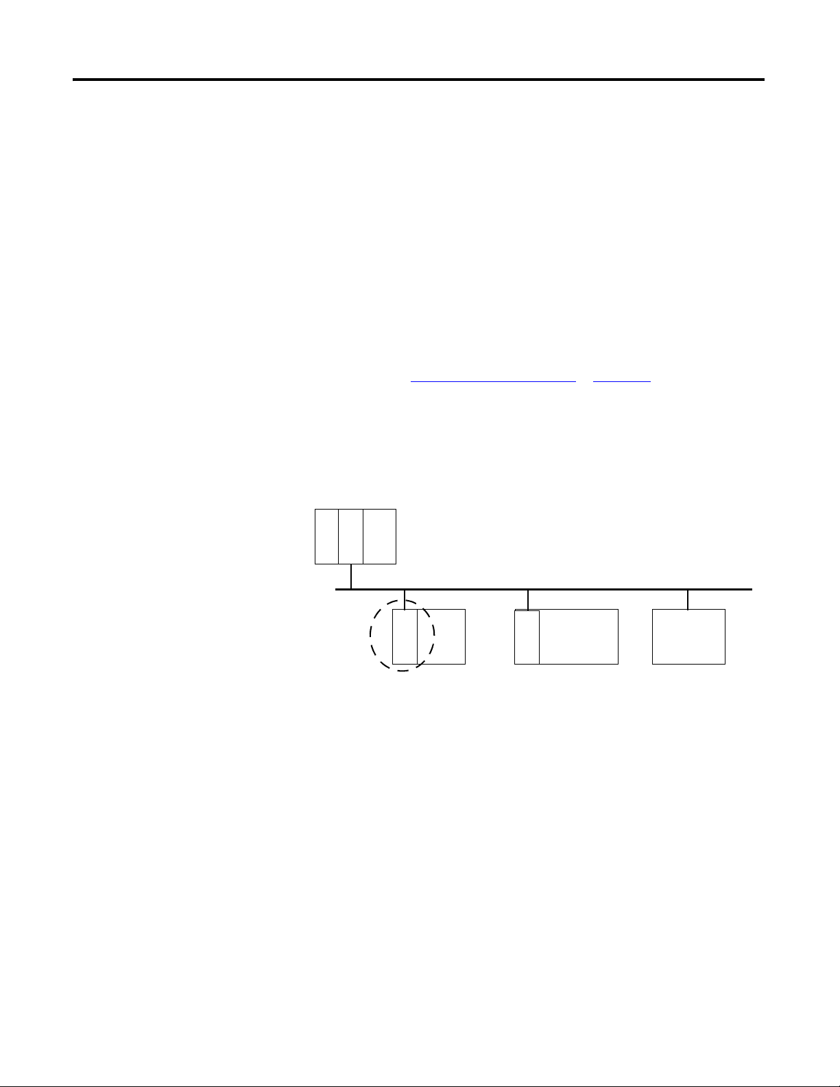
What the Adapter Does
The I/O adapters perform the following primary tasks:
• Control of real-time I/O data (also known as implicit messaging) - the
adapter serves as a bridge between I/O modules and the network
• Support of messaging data for configuration and programming
information (also known as explicit messaging)
L
6
3
EtherNet/IP Network
E
N
B
T
Other
Network
Devices
A
E
N
T
POINT
I/O
E
N
B
T
ControlLogix
I/O
Rockwell Automation Publication 1738-UM005A-EN-P - July 2013 3
Overview of the 1738 ArmorPOINT I/O EtherNet/IP Adapter Chapter 1
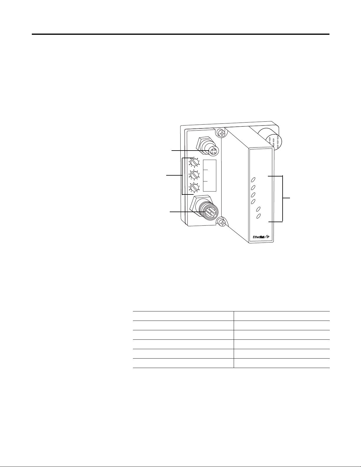
Physical Features of Your
Adapter
The 1738 Adapter has the following components:
• One EtherNet/IP Female M12 connector
• Network address Switches
• Mini Style 4-Pin in Male Auxiliary Power Connector
• Status indicators (Module Status; Network Status; POINTBus Status;
Network Activity; System Power; Adapter Power)
Physical Features of the 1738-AENT/B Adapters
Hardware/Software
Compatibility
The I/O adapter and the software applications described in this manual are
compatible with the following firmware revisions and
software releases.
Contact Rockwell Automation if you need software or firmware upgrades to use
this equipment
1738-AENT
Series B
EtherNet I/P
Adapter
Status
Network
Activity
Network
Status
PointBus
Status
System
Power
Adapter
Power
X100
X10
X1
c
onformanc
e t
est
ed
™
PWR
P
A
D
D
R
E
S
S
I
M12 Female in
connector
Mini-style 4-pin in
Male Connector
43798
Status indicators
Product Firmware Revision/ Software Release
1738-AENT Series B adapters 4.002 or later
1756-ENBT 4.5 or later
Logix Controller 17 or later
RSLogix 5000 software 17 or later
RSLinx software 2.56 or later

4 Rockwell Automation Publication 1738-UM005A-EN-P - July 2013
Chapter 1 Overview of the 1738 ArmorPOINT I/O EtherNet/IP Adapter
Important Adapter
Considerations
Before you begin using your adapter, note the following important
considerations.
Set the Chassis Size
The ArmorPOINT I/O adapters require configuration of their chassis size before
you can make any I/O connections. The factory default setting for the chassis size
is one slot, which represents the adapter by itself.
You must set the chassis size to a number equaling one slot for the adapter plus
one slot for each I/O module present in the backplane of the adapter.
For example, an ArmorPOINT I/O system consisting of a 1738-AENT adapter,
one 1738-IB8, one 1738-OB8, and one 1738-OB8S POINTGuard I/O module
uses a chassis size of 4. The adapter stores this chassis size setting in non-volatile
memory.
Each time the adapter is powered up, the adapter compares the number of I/O
modules present on its backplane to the chassis size value from non-volatile
memory. The adapter does not allow any I/O connection until the number of
I/O modules present equals the chassis size value minus one for the adapter itself.
Adapter
Replacement
Note that during a connection request from the controller, the chassis size setting
is not communicated to the adapter. You must always set this chassis size using a
separate operation. This includes situations when you are replacing an adapter.
The adapter does not allow any I/O connections until it is configured with the
appropriate chassis size and the proper number of ArmorPOINT I/O modules
are present.
Empty Slots and RIUP Situations
The ArmorPOINT I/O system cannot detect an empty terminal base. For this
reason, there are numerous situations in which you can potentially configure a
system that is unusable or one that exercises unintended control.
In an attempt to address these situations, you must observe the following rules for
I/O system construction and the
removal and reinsertion of modules.
• A correct I/O system does not have any empty terminal bases.
• After you cycle power, the adapter will not allow any I/O connections
until the number of modules comprising the chassis plus one for the
adapter equals the stored chassis size.

Rockwell Automation Publication 1738-UM005A-EN-P - July 2013 5
Overview of the 1738 ArmorPOINT I/O EtherNet/IP Adapter Chapter 1
– It cannot assume any safe operation until there is a match between the
number of modules indicating their presence in the chassis and what the
adapter has saved in non-volatile memory because it cannot detect
empty terminal bases.
– Actual module identification (such as, electronic keying) is done when
connection establishment requests are received from the controller or
controllers.
• A POINT I/O module removed under power does not disrupt operation
of the other I/O modules. On the other hand, ArmorPOINT I/O
modules are not intended to be removed under power.
• If more than one contiguous module is removed under power, connections
to all modules in the contiguous missing module set are disallowed until all
modules are replaced. Because the adapter cannot detect an empty base, it
does not know the physical positioning of the modules until all the missing
modules are replaced.
• If a module separating two sets of contiguous missing modules is removed,
the two sets merge into a single set. All the modules must be replaced
before connections are permitted to any module in the set.
• If modules of different types are removed and returned to the wrong
locations, attempts to connect to these modules will fail during verification
of the electronic ID (providing that keying has not been disabled).
• If modules of the same type are removed and returned to the wrong
locations, they accept connections from the controller or controllers and
reconfigure with the correct data once they pass their electronic keying
check.
• These removal and return situations exist whether the system is under
power or not. If the system is under power, the situation arises immediately.
If the system is not under power, the situation arises in the next power
cycle.
Power Up a System for the First Time
When you power the I/O for the first time, the adapter must assign slot addresses
to every module in the backplane. All I/O modules ship configured at the same
address.
When you first apply power, we expect that all but one module on the backplane
exhibits a solid red Module Status LED.
One by one the adapter resets these modules and addresses them appropriately.
The amount of time that this operation takes is proportional to the size of your
I/O system.

6 Rockwell Automation Publication 1738-UM005A-EN-P - July 2013
Chapter 1 Overview of the 1738 ArmorPOINT I/O EtherNet/IP Adapter
Use of the Common
Industrial Protocol (CIP)
The adapter uses the Common Industrial Protocol (CIP). CIP is the application
layer protocol specified for EtherNet/IP, the Ethernet Industrial Protocol, as well
as for ControlNet and DeviceNet networks. It is a message-based protocol that
implements a relative path to send a message from the producing device in a
system to the consuming devices.
The producing device contains the path information that steers the message along
the proper route to reach its consumers. Since the producing device holds this
information, other devices along the path simply pass this information; they do
not store it.
This has the following significant benefits:
• You do not need to configure routing tables in the bridging modules,
which greatly simplifies maintenance and module replacement.
• You maintain full control over the route taken by each message, which
enables you to select alternative paths for the same end device.
Understand the Producer/
Consumer Model
The CIP producer and consumer networking model replaces the old source and
destination (master and slave) model. The producer and consumer model reduces
network traffic and increases speed of transmission. In traditional I/O systems,
controllers poll input modules to obtain their input status. In the CIP system,
input modules are not polled by a controller. Instead, they produce (multicast or
unicast) their data either upon a change of state (COS) or periodically.
Multicast is the default mode for version 17 Logix and earlier controllers and
unicast is the default for version 18 with multicast as a selectable option.
The frequency of update depends upon the options chosen during configuration
and where on the network the input module resides. The input module,
therefore, is a producer of input data, and the controller is a consumer of the data.
The controller also produces data for other controllers to consume. The
produced and consumed data is accessible by multiple controllers and other
devices over the EtherNet/IP network. This data exchange conforms to the
producer and consumer model.
Specify the
Requested
Packet Interval (RPI)
The Requested Packet Interval or RPI is the update rate specified for a particular
piece of data on the network. The RPI can be specified for the adapter and
include all of the I/O modules in the I/O system (using a rack-optimized
connection) or specified for a particular module (using direct connection).
When you add a module or an adapter to the I/O configuration of a controller,
you must enter the RPI as a parameter. This value specifies how often to produce
the data for that device. For example, if you specify an RPI of 50 ms, it means that

Rockwell Automation Publication 1738-UM005A-EN-P - July 2013 7
Overview of the 1738 ArmorPOINT I/O EtherNet/IP Adapter Chapter 1
every 50 ms the device should send its data to the controller and the controller
should send the consumed (output) data to the device.
Use RPIs only for devices that exchange data. For example, a ControlLogix
EtherNet/IP bridge module in the same chassis as the controller does not require
an RPI, because it is not a data-producing member of the system. Its use is only as
a bridge to remote racks.
Support for Rack-optimized
and Direct Connections
The I/O adapter supports both direct and rack-optimized connections. A direct
connection is a real-time data transfer link between the controller and the module
occupying the slot that the configuration data references.
Direct I/O connections occur at a cyclic rate specified by the RPI during
configuration. A rack-optimized connection is a grouping of data from one or
more digital I/O modules into a single block of data sent over a single connection
at the same data rate.
Analog, safety, and speciality modules cannot participate in the rack-optimized
connection; these modules require a direct I/O connection.
Rack-optimized connections reduce the total number of connections needed to
transfer data when using many digital I/O modules in a system. The following
example illustrates the benefit of rack-optimized connections.
Assume you set up a system that contains eight digital I/O modules interfaced to
an adapter. If you use direct connections to transfer data to each of the these I/O
modules, you need eight connections to transfer all of the data, one to each of the
eight I/O modules. If you use a rack-optimized connection to transfer the data,
you only need a single connection – the connection to the I/O adapter.
See the EtherNet/IP Embedded Switch Technology Application Guide,,
publication ENET-AP005
, for more information on connections.
IMPORTANT
Although rack-optimized connections offer an efficient way to use
resources, there are a few limitations on their use:
• You can use only rack-optimized connections to send data to and
from digital I/O modules. Analog or speciality I/O requires direct
connections.
• All data is sent at the same time as the RPI rate of the I/O adapters.
If the update rate required for a digital module is different from the
RPI of the rack-optimized connection, a direct connection to that
digital I/O module is required.

8 Rockwell Automation Publication 1738-UM005A-EN-P - July 2013
Chapter 1 Overview of the 1738 ArmorPOINT I/O EtherNet/IP Adapter
Mixing Rack-optimized and Direct Connections
You can mix communication formats for different I/O modules communicating
through the same adapter. I/O modules set up to use rack optimization
communicate at the rate of the RPI configured for the adapter. I/O modules
configured for direct communication communicate at their own individual RPIs
and ignore the rack-optimized RPI.
Chapter Summary
In this chapter, you were introduced to the features of the ArmorPOINT I/O
Adapter, and considerations for installation and usage.
Rockwell Automation Publication 1738-UM005A-EN-P - July 2013 9
Chapter
2
Install Your ArmorPOINT I/O Adapter
Overview
This chapter describes how to install and wire your module. This chapter includes
the following topics:
Topic Page
Mount the Adapter and I/O Base 10
Install the ArmorPOINT I/O Modules 11
Remove an ArmorPoint I/O Module 11
Wire an ArmorPOINT I/O Adapter 12
Chapter Summary 12
ATT ENTI ON: To comply with the CE Low Voltage Directive (LVD), this
equipment must be powered from a source compliant with the
following:
Safety Extra Low Voltage (SELV) or Protected Extra Low Voltage (PELV).
ATTENTION: This product is intended to be mounted to a well-
grounded mounting surface such as a metal panel. Additional
grounding connections from the power supply's mounting tabs or DIN
rail (if used) are not required unless the mounting surface cannot be
grounded. Refer to Industrial Automation Wiring and Grounding
Guidelines, Rockwell Automation publication 1770-IN041
, for
additional information.
ATTENTION: If this equipment is used in a manner not specified by the
manufacturer, the protection provided by the equipment may be
impaired.
ATTENTION: To comply with the CE Low Voltage Directive (LVD), this
equipment must be powered from a source compliant with the
following:
Safety Extra Low Voltage (SELV) or Protected Extra Low Voltage (PELV).
10 Rockwell Automation Publication 1738-UM005A-EN-P - July 2013
Chapter 2 Install Your ArmorPOINT I/O Adapter
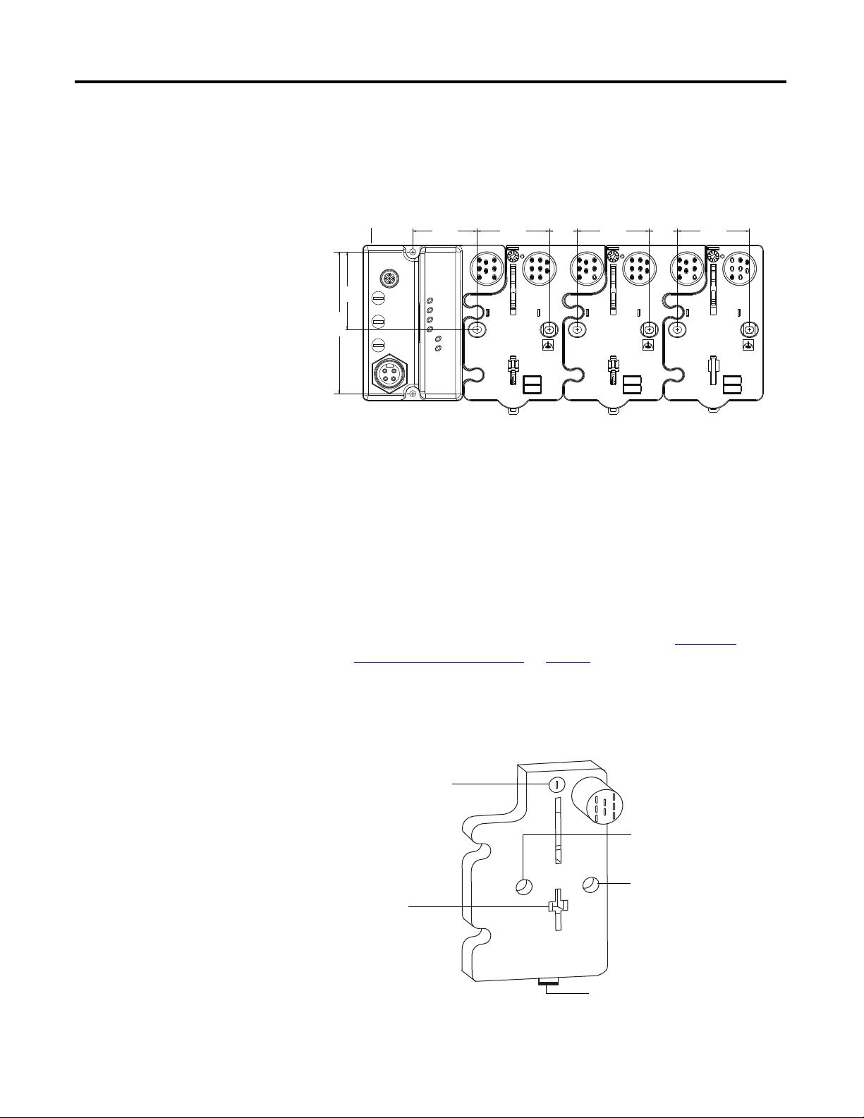
Mount the Adapter and I/O
Base
To mount the adapter on a wall or panel, use the screw holes provided in the
adapter. A mounting illustration for the adapter with several attached I/O bases is
shown below.
Mounting illustration for the ArmorPOINT adapter and I/O Mounting bases
Install the adapter and its I/O mounting base as follows:
1. Lay out the required points as shown above in the drilling dimension
drawing.
2. Drill the necessary holes for M4 (#8) machine or self-tapping screws.
3. Mount the adapter using M4 (#8) screws.
4. Ground the system using the ground lug connection in the adapter’s I/O
Mounting base. (The ground lug connection is also a mounting hole).
5. Add one or more I/O modules and their respective I/O Mounting bases to
the adapter and its I/O Mounting base as required. See Install the
ArmorPOINT I/O Modules on page 11 for details.
6. Mount the terminating base shipped with the adapter as the last base in the
backplane instead of the I/O Mounting base shipped with the I/O
module.
43769
52 mm
(2.05 in)
52 mm
(2.05 in)
52 mm
(2.05 in)
20 mm
(0.79 in)
20 mm
(0.79 in)
56 mm
(2.20 in)
Adapter
46.2 mm
(1.82 in)
102 mm
(4.02 in.)
43787
Mounting hole
Ground lug connection
Keyswitch
Latching
mechanism hole
Terminating Base
Latching mechanism
Rockwell Automation Publication 1738-UM005A-EN-P - July 2013 11
Install Your ArmorPOINT I/O Adapter Chapter 2
7. Set the network rotary switches to the desired value. See Set the Network
Address for ArmorPOINT I/O Adapters in Chapter 3 for details on
setting the IP address.
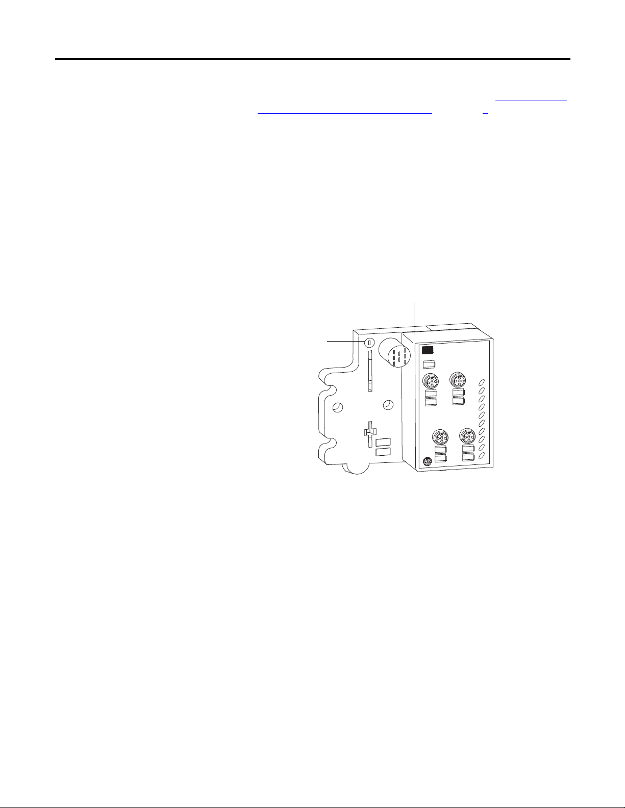
Install the ArmorPOINT I/O Modules
To install the ArmorPOINT I/O modules,
1. Using a bladed screwdriver, rotate the keyswitch on the I/O module
mounting base clockwise until the appropriate number for the I/O module
you are installing aligns with the notch in the I/O module mounting base.
2. Position the I/O module vertically above the I/O module mounting base.
The module bridges two I/O module mounting bases.
3. Push the module down until it engages the latching mechanism.
You hear a clicking sound when the module is properly engaged. The
locking mechanism locks the I/O module to the I/O module mounting
base.
Remove an ArmorPoint I/O Module
To remove a module from its mounting base:
1. Put a flat-blade screwdriver into the slot of the orange latching mechanism.
2. Push the screwdriver toward the I/O module to disengage the latch.
The module lifts up off the base.
3. Pull the module off the base.
MOD
NET
0
1
2
3
4
5
6
7
1738-OB8EM12/A
24V dc Out
0
1
2
3
4
5
6
7
43771
Module Bridges Two Bases
Set keyswitch
position to 4 for the
1738 analog output
modules
12 Rockwell Automation Publication 1738-UM005A-EN-P - July 2013
Chapter 2 Install Your ArmorPOINT I/O Adapter
Wire the Adapter
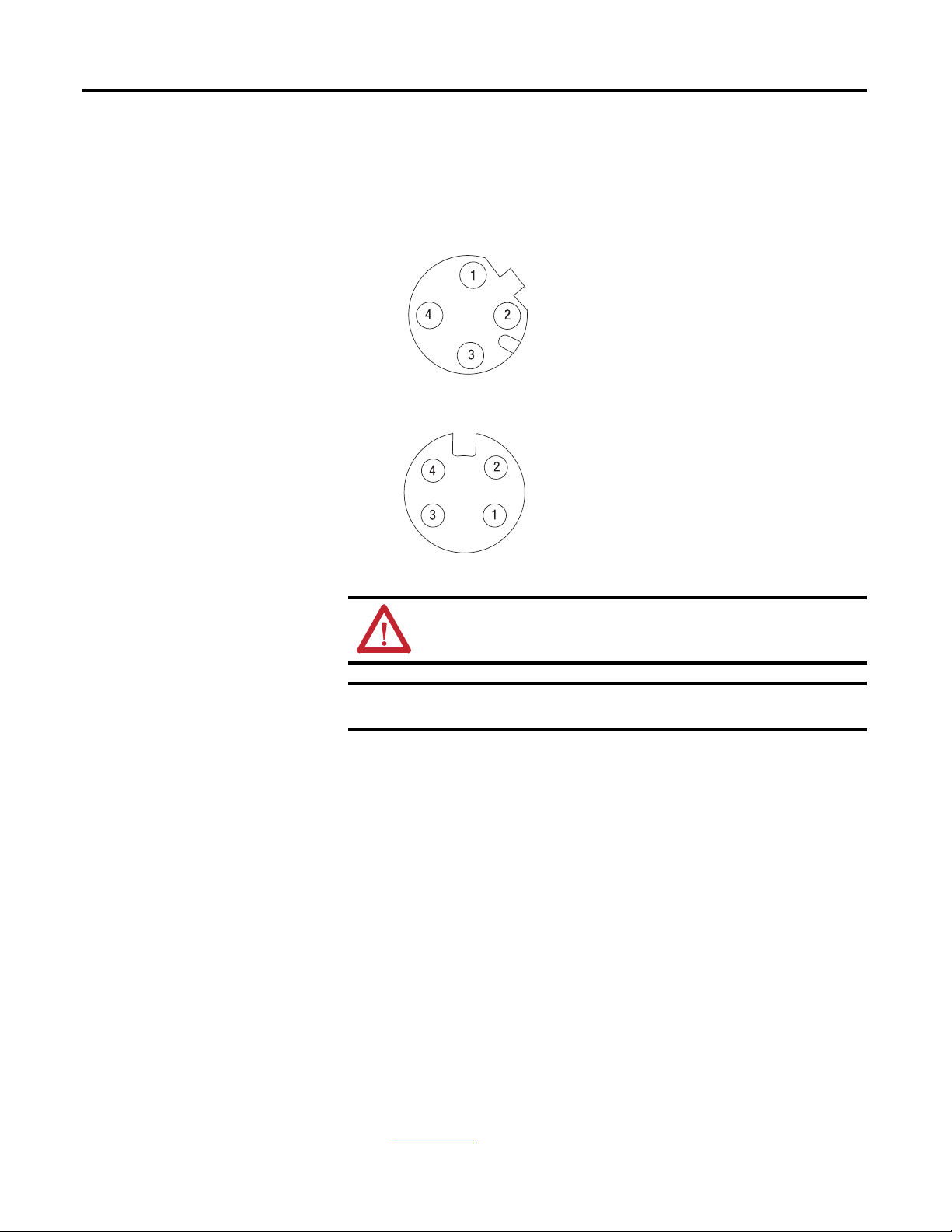
Wire an ArmorPOINT I/O Adapter
Refer to the following illustration to wire the adapter
EtherNet/IP Connectors
Auxiliary Power Connector
(1)
Chapter Summary
In this chapter, you learned how to install and wire your EtherNet/IP adapter.
The following chapter describes how to configure the adapter to communicate on
your EtherNet/IP network by providing an IP address, gateway address, and
Subnet mask.
ATTENTION: Make sure all connectors and caps are securely tightened
to properly seal the connections against leaks and maintain IP enclosure
type requirements.
IMPORTANT
Analog modules have earth grounded metal rings. This should be
considered when choosing shielded cables and grounding techniques.
(1) Auxiliary power cable: standard cordset (single-ended), for example Allen-Bradley part number 889N-F4AFC-6F or 889N-R4AFC-
6F; or standard patchcord (double-ended), for example, Allen-Bradley part number 889N-F4AFNU-6F or 889N-F4AFNV-6F. Refer to
publication M117-CA001A-EN-P
for more information.
(view into connector)
Pin 1 - Tx +
Pin 2 - Rx +
Pin 3 - Tx -
Pin 4 - Rx -
M12 Female in Connector
43765
43587
Mini Style 4-Pin in Male Connector
(view into connector)
Pin 1 - User Power +
Pin 2 - Adapter Power +
Pin 3 - Adapter Power -
Pin 4 - User Power -

Rockwell Automation Publication 1738-UM005A-EN-P - July 2013 13
Chapter
3
Configure the Adapter with RSLogix5000
software
Introduction
This chapter guides you through the steps required to configure your modules
using the RSLogix 5000 software. Note that the modules presented in this
chapter can be configured using RSLogix 5000 software, version 17, or later.
Before using your adapter in an EtherNet/IP network, you need to configure it
with an IP address, subnet mask, and optional Gateway address. This chapter
describes these configuration requirements and the procedures for providing
them. Here are ways you can do this:
• Use the Rockwell BootP/DHCP utility, version 2.3 or later, that ships
with RSLogix 5000 or RSLinx software.
– You can also use this utility to reconfigure a device with an IP address
you must change.
• Use a
third party DHCP server.
• Use the Network Address rotary switches.
• Have your network administrator configure the adapter via the network
DHCP server.
See the table for where to find information in this chapter.
Topic Page
Configuration Requirements
14
IP Address 14
Gateway Address 15
Subnet Mask 16
Set the Network Address 17
Set the Network Address for ArmorPOINT I/O Adapters 17
Use the Rockwell BootP/DHCP Utility 18
Save the Relation List 21
Use DHCP Software to Configure Your Adapter 22

14 Rockwell Automation Publication 1738-UM005A-EN-P - July 2013
Chapter 3 Configure the Adapter with RSLogix5000 software
Configuration
Requirements
Before you can use your adapter, you must configure its IP address, its subnet
mask, and, optionally, a gateway address. You can use the Rockwell BootP utility,
version 2.3 or later, to perform the
configuration. You can also use a DHCP
server or the network address rotary switches to configure these parameters.
If you need to reset the adapter to factory defaults, see Work with the
Configuration Pages on page 92.
IP Address
The IP address identifies each node on the IP network (or system of connected
networks). Each TCP/IP node on a network (including the adapter) must have a
unique IP address.
The IP address is 32 bits long and has a Network ID part and Host ID part.
Networks are classified A, B, C, (or other). The class of the network determines
how an IP address is formatted
.
You can distinguish the class of the IP address from the first integer in its dotted-
decimal IP address as follows:
Each node on the same physical network must have an IP address of the same
class and must have the same network ID. Each node on the same network must
have a different Host ID thus giving it a unique IP address.
IMPORTANT
If using the BootP/DHCP utility, you will need to know the Ethernet
hardware address of your module. Rockwell assigns each 1738
ArmorPOINT I/O Ethernet/IP Module a unique 48-bit hardware
address at the factory. The address is printed on a label on the side of
your module. It consists of six hexadecimal digits separated by colons.
This address is fixed by the hardware and cannot be changed.
If you change or replace the 1738 ArmorPOINT I/O Ethernet/IP
Module, you must enter the new Ethernet hardware address of the
module when you configure the new module.
Class A
Class B
Class C
Network ID
Host ID
Host ID
Host ID
0
0
0
10
0
110
78
15 16
31
31
3123 24
Network ID
Network ID
Range of first integer Class Range of first integer Class
0 1…127 A 192…223 C
128…191 B 224… 255 other
Rockwell Automation Publication 1738-UM005A-EN-P - July 2013 15
Configure the Adapter with RSLogix5000 software Chapter 3
IP addresses are written as four decimal integers (0…255) separated by periods
where each integer gives the value of one byte of the IP address
.
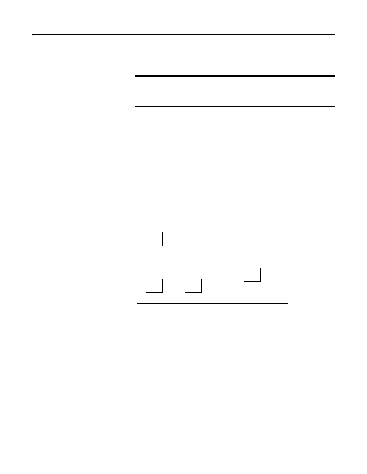
Gateway Address
This section applies to multi-network systems. If you have a single network
system, refer to the next section.
The Gateway Address is the default address of a network. It provides a single
domain name and point of entry to the site. Gateways connect individual physical
networks into a system of networks.
When a node needs to communicate with a node on another network, a gateway
transfers the data between the two networks. The figure shows gateway G
connecting Network 1 with Network 2.
When host B with IP address 128.2.0.1 communicates with host C, it knows
from C’s IP address that C is on the same network. in an Ethernet environment, B
can then resolve C’s IP address into a hardware address (MAC address) and
communicate with C directly.
When host B communicates with host A, it knows from A’s IP address that A is
on another network (the network IDs are different). In order to send data to A, B
must use the IP address of the gateway connecting the two networks. In this
example, the gateway’s IP address on Network 2 is 128.2.0.3.
The gateway has two IP addresses (128.1.0.2 and 128.2.0.3). The first must be
used by hosts on Network 1 and the second must be used by hosts on Network 2.
To be usable, a gateway of a host must be addressed using a network ID matching
its own.
EXAMPLE
For example, the 32-bit IP address:
10000000 00000001 00000000 00000001 is written as
128.1.0.1
Network 1
Network 2
128.1.0.1
128.2.0.1 128.2.0.2 128.2.0.3
128.1.0.2
A
B
G
C
16 Rockwell Automation Publication 1738-UM005A-EN-P - July 2013
Chapter 3 Configure the Adapter with RSLogix5000 software
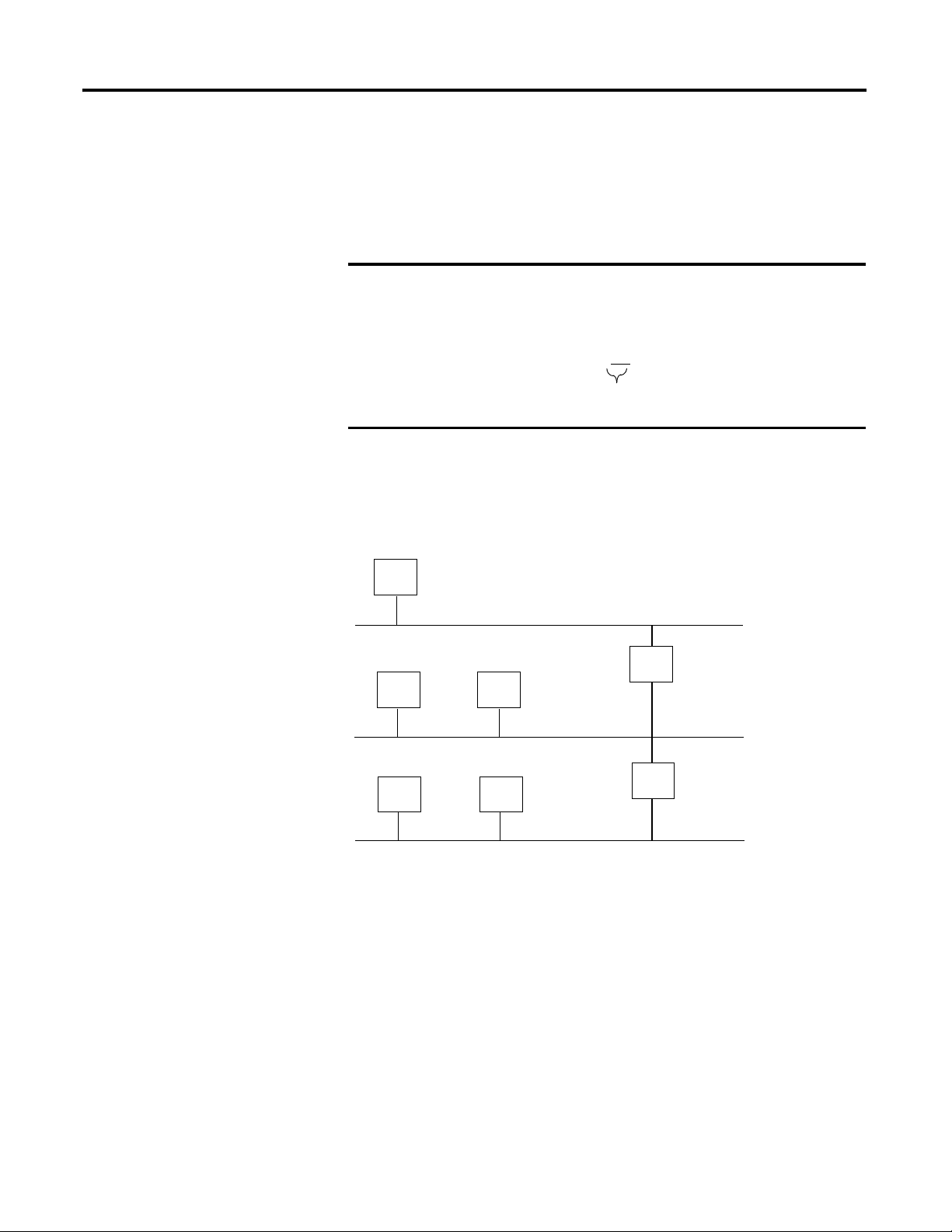
Subnet Mask
The subnet mask is used for splitting IP networks into a series of subgroups, or
subnets. The mask is a binary pattern that is matched up with the IP address to
turn part of the Host ID address field into a field for subnets
.
Two bits of the Class B host ID are used to extend the network ID. Each unique
combination of bits in the part of the Host ID where subnet mask bits are 1
specifies a different physical network.
The new configuration is:
A second network with Hosts D and E was added. Gateway G2 connects
Network 2.1 with Network 2.2.
Hosts D and E will use Gateway G2 to communicate with hosts not on
Network 2.2.
Hosts B and C will use Gateway G to communicate with hosts not on
Network 2.1.
When B is communicating with D, G (the configured Gateway for B) will route
the data from B to D through G2.
EXAMPLE
Take Network 2 (a Class B network) in the previous
example and add another physical network. Selecting the
following subnet mask would add two additional
network ID bits, allowing for four physical networks:
11111111 11111111 11
000000 00000000 = 255.255.192.0
These two bits of the Host ID are used to
extend the netdwork ID.
Network 1
Network 2.1
Network 2.2
A
BC
DE
128.1.0.2
128.1.0.1
128.2.64.3
128.2.128.2
128.2.64.1 128.2.64.2
128.2.128.3
128.2.128.1
G2
G

Rockwell Automation Publication 1738-UM005A-EN-P - July 2013 17
Configure the Adapter with RSLogix5000 software Chapter 3
Set the
Network Address
The adapters ship DHCP-enabled and with the switches set to 999. You can set
the network Internet Protocol (IP) address as follows.
Set the Network Address for ArmorPOINT I/O Adapters
• Adjust the rotary switches in front of the module
• Use a Dynamic Host Configuration Protocol (DHCP) server such as
Rockwell Automation BootP/DHCP
• Retrieve the IP address from non-volatile memory
The adapter reads the rotary switches first to determine if they are set to a valid
number. Set the network address by adjusting the three rotary switches on the
front of the adapter.
Figure 1 - Network Address Example
Use a small blade screwdriver to rotate the switches. Line up the small notch on
the switch with the number setting you wish to use. Valid settings range from
001…254.
When you use the switches to assign an address and set it to 001, the adapter
gateway address is set to 0.0.0.0. and the subnet mask is 255.255.255.0 . When
you use the switches to assign an address and set it to a valid number between
002...254, the adapter gateway address is set to 192.168.1.1.
If the switches are set to an invalid number (for example, 000 or a value greater
than 254 excluding 888), the adapter checks to see if DHCP is enabled. If DHCP
is enabled, the adapter requests an address from a DHCP server. The DHCP
server also assigns other Transport Control Protocol (TCP) parameters.
If DHCP is not enabled, the adapter uses the IP address, along with other TCP
configurable parameters, stored in non-volatile memory.
WARNING: When you change switch settings while power is on, an
electrical arc can occur. This could cause an explosion in hazardous
location installations.
Be sure that power is removed or the area is nonhazardous before
proceeding.
44831
This example shows the network address
set at 163.
18 Rockwell Automation Publication 1738-UM005A-EN-P - July 2013
Chapter 3 Configure the Adapter with RSLogix5000 software
Use the Rockwell BootP/
DHCP Utility
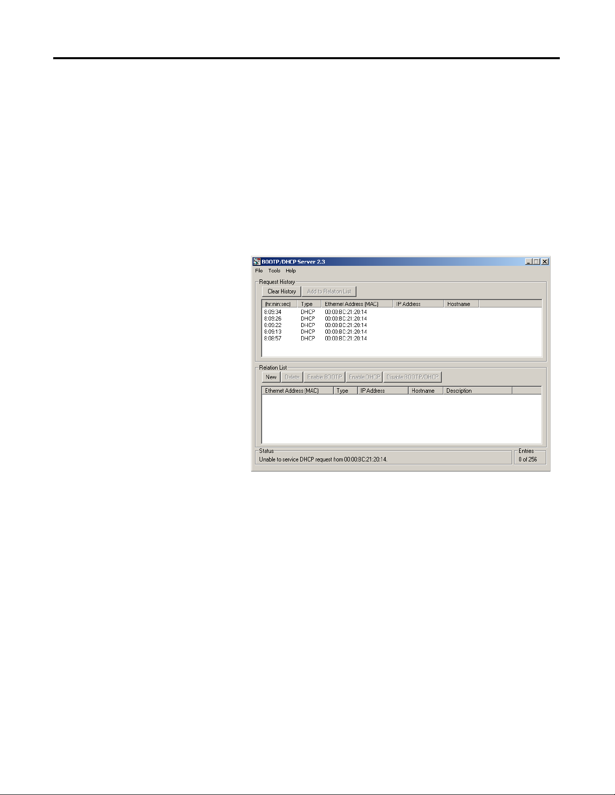
The Rockwell BootP/DHCP utility is a standalone program that incorporates
the functionality of standard BootP software with a user-friendly graphical
interface. It is located in the Ut ils directory on the RSLogix5000 software
installation CD. The adapter must have DHCP enabled (factory default and the
network address switches set to an invalid value) to use the utility.
To configure your adapter using the BootP utility, perform the following steps:
1. Run the BootP software.
In the BOOTP Request History panel you see the hardware addresses of
devices issuing BootP requests.
Rockwell Automation Publication 1738-UM005A-EN-P - July 2013 19
Configure the Adapter with RSLogix5000 software Chapter 3
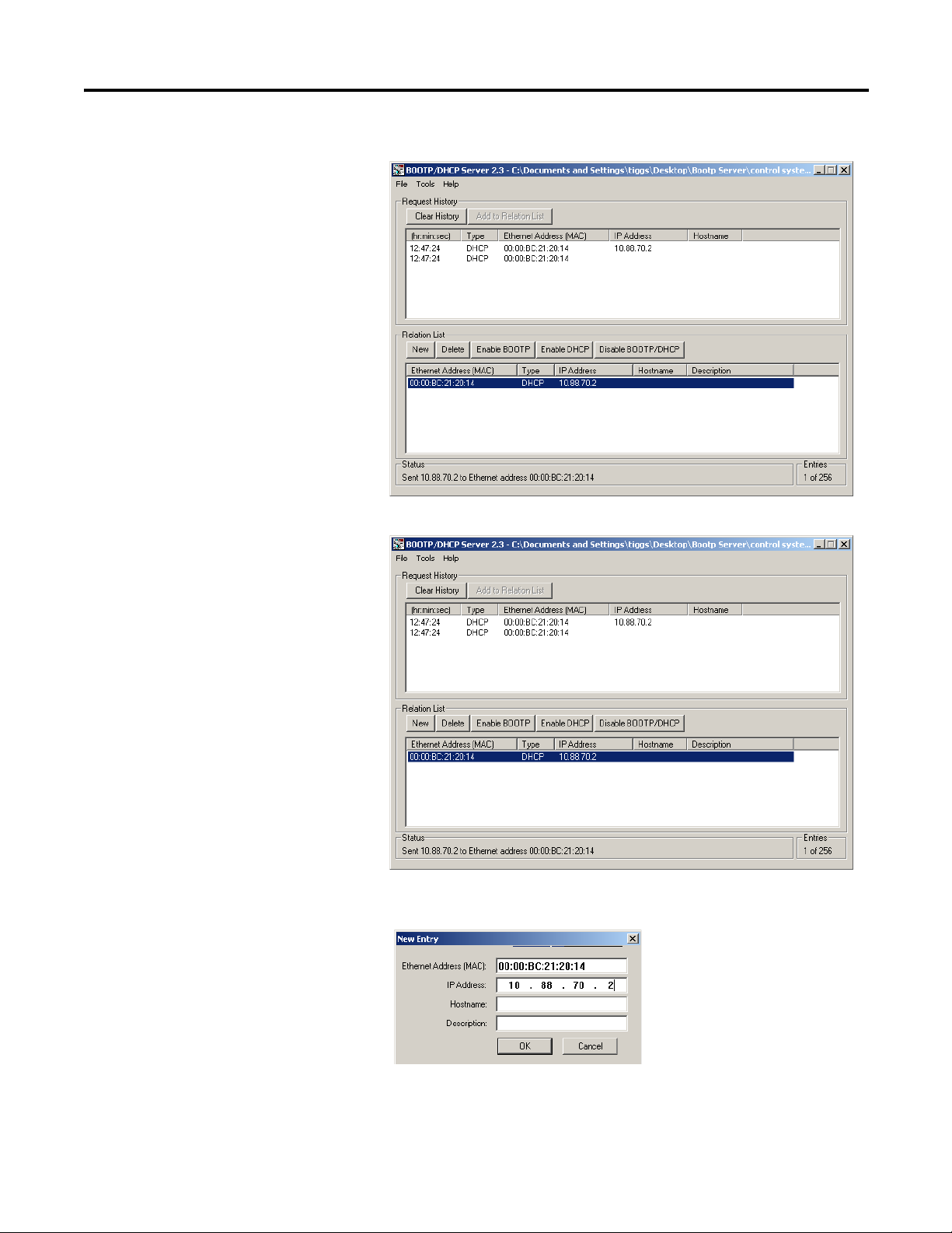
2. Double-click the hardware address of the device you want to configure.
The New Entry dialog appears with the device’s Ethernet Address (MAC).
20 Rockwell Automation Publication 1738-UM005A-EN-P - July 2013
Chapter 3 Configure the Adapter with RSLogix5000 software
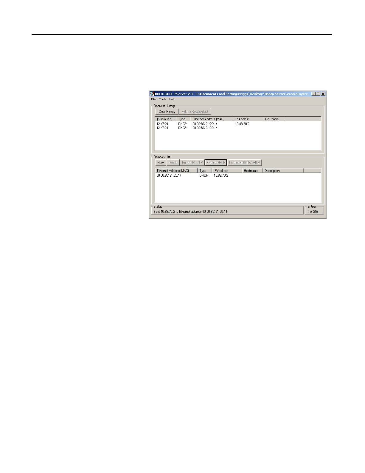
3. Enter the IP Address you want to assign to the device and click OK. The
device is added to the Relation List, displaying the Ethernet Address
(MAC) and corresponding IP Address, Hostname, and Description (if
applicable).
When the address displays in the IP Address column in the Request History
section, the IP address assignment has been made.
4. To make this configuration static in the device, highlight the device in the
Relation List panel, and click the Disable BOOTP/DHCP button.
When power is cycled to the device, it uses the configuration saved in non-
volatile memory and will not issue a DHCP request.
5. To enable DHCP for a device with DHCP disabled, highlight the device
in the Relation List, and click the Enable DHCP button.
You must have an entry for the device in the Relation List panel to re-
enable DHCP.
Loading...