


 Loading...
User Manual
ControlLogix High-speed Counter Module
Catalog Numbers 1756-HSC

Important User Information
Solid-state equipment has operational characteristics differing from those of electromechanical equipment. Safety Guidelines for the Application, Installation and Maintenance of Solid State Controls (publication SGI-1.1 available from your local Rockwell Automation® sales office or online at http://www.rockwellautomation.com/literature/) describes some important differences between solid-state equipment and hard-wired electromechanical devices. Because of this difference, and also because of the wide variety of uses for solid-state equipment, all persons responsible for applying this equipment must satisfy themselves that each intended application of this equipment is acceptable.
In no event will Rockwell Automation, Inc. be responsible or liable for indirect or consequential damages resulting from the use or application of this equipment.
The examples and diagrams in this manual are included solely for illustrative purposes. Because of the many variables and requirements associated with any particular installation, Rockwell Automation, Inc. cannot assume responsibility or liability for actual use based on the examples and diagrams.
No patent liability is assumed by Rockwell Automation, Inc. with respect to use of information, circuits, equipment, or software described in this manual.
Reproduction of the contents of this manual, in whole or in part, without written permission of Rockwell Automation, Inc., is prohibited.
Throughout this manual, when necessary, we use notes to make you aware of safety considerations.
WARNING: Identifies information about practices or circumstances that can cause an explosion in a hazardous environment, which may lead to personal injury or death, property damage, or economic loss.
ATTENTION: Identifies information about practices or circumstances that can lead to personal injury or death, property damage, or economic loss. Attentions help you identify a hazard, avoid a hazard, and recognize the consequence.
SHOCK HAZARD: Labels may be on or inside the equipment, for example, a drive or motor, to alert people that dangerous voltage may be present.
BURN HAZARD: Labels may be on or inside the equipment, for example, a drive or motor, to alert people that surfaces may reach dangerous temperatures.
IMPORTANT Identifies information that is critical for successful application and understanding of the product.
Allen-Bradley, Rockwell Software, Rockwell Automation, ControlLogix, RSLogix, Logix5000, PHOTOSWITCH, RSNetWorx, and TechConnect are trademarks of Rockwell Automation, Inc.
Trademarks not belonging to Rockwell Automation are property of their respective companies.

Summary of Changes
New and Updated
Information
This manual contains new and updated information. Changes throughout this revision are marked by change bars, as shown to the right of this paragraph.
This table contains the changes made to this revision.
Topic |
Page |
|
|
|
|
||
|
|
|
|
The Attention and Warning tables have been updated. |
39 |
|
|
|
|
||
|
|
|
|
Rockwell Automation Publication 1756-UM007C-EN-P - November 2011

4Summary of Changes
Notes:
Rockwell Automation Publication 1756-UM007C-EN-P - November 2011

|
Table of Contents |
|
Preface |
About This Publication . . . . . . . . . . . . . . . . . . . . . . . . . . . . . . . . . . . . . |
. 9 |
|
Who Should Use This Manual. . . . . . . . . . . . . . . . . . . . . . . . . . . . . . . . . |
9 |
|
Additional Resources . . . . . . . . . . . . . . . . . . . . . . . . . . . . . . . . . . . . . . . |
10 |
|
Chapter 1 |
|
1756-HSC Module Features |
Introduction . . . . . . . . . . . . . . . . . . . . . . . . . . . . . . . . . . . . . . . . . . . . . . |
11 |
|
What is a High-speed Counter Module? . . . . . . . . . . . . . . . . . . . . . . . . |
11 |
|
Encoder and Sensor Compatibility . . . . . . . . . . . . . . . . . . . . . . . . . . . . |
13 |
|
1756-HSC/B Module Features . . . . . . . . . . . . . . . . . . . . . . . . . . . . . . . |
13 |
|
Additional I/O Module Features . . . . . . . . . . . . . . . . . . . . . . . . . . |
14 |
|
1756-HSC Parts Illustration . . . . . . . . . . . . . . . . . . . . . . . . . . . . . . |
15 |
|
Chapter 2 |
|
Counter Modes |
Introduction . . . . . . . . . . . . . . . . . . . . . . . . . . . . . . . . . . . . . . . . . . . . . . |
17 |
|
Counter/Encoder Overview . . . . . . . . . . . . . . . . . . . . . . . . . . . . . . . . . |
17 |
|
Counter Mode . . . . . . . . . . . . . . . . . . . . . . . . . . . . . . . . . . . . . . . . . |
19 |
|
Encoder Mode . . . . . . . . . . . . . . . . . . . . . . . . . . . . . . . . . . . . . . . . . |
20 |
|
Preset . . . . . . . . . . . . . . . . . . . . . . . . . . . . . . . . . . . . . . . . . . . . . . . . |
22 |
|
Rollover . . . . . . . . . . . . . . . . . . . . . . . . . . . . . . . . . . . . . . . . . . . . . . |
22 |
|
Input Z (Gate/Reset) . . . . . . . . . . . . . . . . . . . . . . . . . . . . . . . . . . . |
23 |
|
Storage Modes . . . . . . . . . . . . . . . . . . . . . . . . . . . . . . . . . . . . . . . . . |
23 |
|
Outputs. . . . . . . . . . . . . . . . . . . . . . . . . . . . . . . . . . . . . . . . . . . . . . . . . . |
26 |
|
Assign Outputs to Counters . . . . . . . . . . . . . . . . . . . . . . . . . . . . . . |
26 |
|
Output Operation . . . . . . . . . . . . . . . . . . . . . . . . . . . . . . . . . . . . . . |
26 |
|
Chapter 3 |
|
Frequency Modes |
Introduction . . . . . . . . . . . . . . . . . . . . . . . . . . . . . . . . . . . . . . . . . . . . . . |
29 |
|
Frequency Overview . . . . . . . . . . . . . . . . . . . . . . . . . . . . . . . . . . . . . . . |
29 |
|
Frequency Mode. . . . . . . . . . . . . . . . . . . . . . . . . . . . . . . . . . . . . . . . . . . |
30 |
|
Sample Period for Frequency Mode . . . . . . . . . . . . . . . . . . . . . . . . |
31 |
|
Period Rate and |
|
|
Continuous Rate Modes. . . . . . . . . . . . . . . . . . . . . . . . . . . . . . . . . . . . . |
32 |
|
Sample Period for Period/Continuous Rate Modes . . . . . . . . . . . |
33 |
|
Output Operation . . . . . . . . . . . . . . . . . . . . . . . . . . . . . . . . . . . . . . . . . |
35 |
|
Period Rate /Continuous Rate Output Examples . . . . . . . . . . . . . . . . |
36 |
|
Maximum Frequency . . . . . . . . . . . . . . . . . . . . . . . . . . . . . . . . . . . . |
37 |
|
Chapter 4 |
|
Install and Wire the ControlLogix |
Introduction . . . . . . . . . . . . . . . . . . . . . . . . . . . . . . . . . . . . . . . . . . . . . . |
39 |
High-speed Counter Module |
Install the 1756-HSC Module . . . . . . . . . . . . . . . . . . . . . . . . . . . . . . . . |
41 |
|
Key the Removable |
|
|
Terminal Block . . . . . . . . . . . . . . . . . . . . . . . . . . . . . . . . . . . . . . . . . . . . |
43 |
|
Wiring the Module . . . . . . . . . . . . . . . . . . . . . . . . . . . . . . . . . . . . . . |
44 |
|
Connect the Wires . . . . . . . . . . . . . . . . . . . . . . . . . . . . . . . . . . . . . . . . . |
44 |
|
Connect Ungrounded End of the Cable. . . . . . . . . . . . . . . . . . . . . |
45 |
Publication 1756-UM007C-EN-P - November 2011

6 Table of Contents |
|
|
|
Two Types of RTBs (each RTB comes with housing) . . . . . . . . . |
46 |
|
Recommendations for Wiring Your RTB . . . . . . . . . . . . . . . . . . . |
47 |
|
Wire Terminations . . . . . . . . . . . . . . . . . . . . . . . . . . . . . . . . . . . . . . . . . |
47 |
|
Wire an Allen-Bradley 845 Incremental Encoder . . . . . . . . . . . . . |
47 |
|
Wire an Allen-Bradley Bulletin 872 3-Wire DC Proximity Sensor 48 |
|
|
Wire a PHOTOSWITCH Series 10,000 Photoelectric Sensor . . . |
49 |
|
Assemble the Removable Terminal Block and Housing . . . . . . . . . . . |
50 |
|
Install the Removable Terminal Block . . . . . . . . . . . . . . . . . . . . . . . . . |
51 |
|
Remove the Removable Terminal Block . . . . . . . . . . . . . . . . . . . . . . . |
52 |
|
Remove the Module |
|
|
from the Chassis . . . . . . . . . . . . . . . . . . . . . . . . . . . . . . . . . . . . . . . . . . |
53 |
|
Chapter 5 |
|
Configure the 1756-HSC Module |
Introduction . . . . . . . . . . . . . . . . . . . . . . . . . . . . . . . . . . . . . . . . . . . . . . |
55 |
|
ControlLogix Overview. . . . . . . . . . . . . . . . . . . . . . . . . . . . . . . . . . . . . |
55 |
|
Direct Connections . . . . . . . . . . . . . . . . . . . . . . . . . . . . . . . . . . . . . |
56 |
|
Local Chassis Operation . . . . . . . . . . . . . . . . . . . . . . . . . . . . . . . . . |
57 |
|
Remote Chassis Operation . . . . . . . . . . . . . . . . . . . . . . . . . . . . . . . |
57 |
|
Use the Default Configuration . . . . . . . . . . . . . . . . . . . . . . . . . . . . |
59 |
|
Configure a 1756-HSC/B, Module by using |
|
|
RSLogix 5000 Software, Version 18 and Later. . . . . . . . . . . . . . . . . . . |
59 |
|
Communication Format Options . . . . . . . . . . . . . . . . . . . . . . . . . . |
62 |
|
Set RPI . . . . . . . . . . . . . . . . . . . . . . . . . . . . . . . . . . . . . . . . . . . . . . . |
64 |
|
Set Up Counter Configuration . . . . . . . . . . . . . . . . . . . . . . . . . . . . . . . |
65 |
|
Filter Selections . . . . . . . . . . . . . . . . . . . . . . . . . . . . . . . . . . . . . . . . |
68 |
|
Set Up Output Configuration . . . . . . . . . . . . . . . . . . . . . . . . . . . . . . . . |
68 |
|
Copy Configuration (.C) Output, Rollover, Preset Tags to Output (.O) |
|
|
Tags . . . . . . . . . . . . . . . . . . . . . . . . . . . . . . . . . . . . . . . . . . . . . . . . . . . . |
71 |
|
Electronic Keying . . . . . . . . . . . . . . . . . . . . . . . . . . . . . . . . . . . . . . . . . |
73 |
|
Download Configuration |
|
|
to the 1756-HSC Module . . . . . . . . . . . . . . . . . . . . . . . . . . . . . . . . . . . |
79 |
|
Chapter 6 |
|
Module Diagnostics |
Introduction . . . . . . . . . . . . . . . . . . . . . . . . . . . . . . . . . . . . . . . . . . . . . . |
81 |
|
1756-HSC Error Codes . . . . . . . . . . . . . . . . . . . . . . . . . . . . . . . . . . . . . |
81 |
|
RSLogix 5000 Diagnostics. . . . . . . . . . . . . . . . . . . . . . . . . . . . . . . . . . . |
82 |
|
Fault Type Determination. . . . . . . . . . . . . . . . . . . . . . . . . . . . . . . . |
84 |
|
Troubleshoot the 1756-HSC Module . . . . . . . . . . . . . . . . . . . . . . . . . . |
84 |
|
Appendix A |
|
1756-HSC Status Indicators |
Introduction . . . . . . . . . . . . . . . . . . . . . . . . . . . . . . . . . . . . . . . . . . . . . . |
85 |
|
Status Indicators. . . . . . . . . . . . . . . . . . . . . . . . . . . . . . . . . . . . . . . . . . . |
85 |
|
Appendix B |
|
1756-HSC Data Structures |
Configuration,Output,Input . . . . . . . . . . . . . . . . . . . . . . . . . . . . . . . . . |
87 |
Publication 1756-UM007C-EN-P - November 2011

|
|
Table of Contents 7 |
|
Configuration Structure. . . . . . . . . . . . . . . . . . . . . . . . |
. . . . . . . . . . 87 |
|
Output Structure . . . . . . . . . . . . . . . . . . . . . . . . . . . . . |
. . . . . . . . . . 89 |
|
Input Structure. . . . . . . . . . . . . . . . . . . . . . . . . . . . . . . |
. . . . . . . . . . 91 |
|
Appendix C |
|
1756-HSC Module History |
Introduction . . . . . . . . . . . . . . . . . . . . . . . . . . . . . . . . . . . . |
. . . . . . . . . . 93 |
|
1756-HSC Profile Overview . . . . . . . . . . . . . . . . . . . . . . . |
. . . . . . . . . . 94 |
|
Configure a Generic Profile. . . . . . . . . . . . . . . . . . . . . . . . |
. . . . . . . . . . 95 |
|
Copy ACD file . . . . . . . . . . . . . . . . . . . . . . . . . . . . . . . |
. . . . . . . . . . 98 |
|
Add Ladder Logic Routines . . . . . . . . . . . . . . . . . . . . |
. . . . . . . . . . 99 |
|
Upgrade Module to Software Version 18 and Later . |
. . . . . . . . . 101 |
|
Edit Thin Profile Tags . . . . . . . . . . . . . . . . . . . . . . . . . . . . |
. . . . . . . . . 102 |
|
Change Configuration |
|
|
Data via Message |
|
|
Instruction . . . . . . . . . . . . . . . . . . . . . . . . . . . . . . . . . . . . . |
. . . . . . . . . 104 |
|
Appendix D |
|
Application Considerations |
Introduction . . . . . . . . . . . . . . . . . . . . . . . . . . . . . . . . . . . . |
. . . . . . . . . 105 |
|
Types of Input Devices . . . . . . . . . . . . . . . . . . . . . . . . . . . |
. . . . . . . . . 105 |
|
Examples for Selecting Input Devices . . . . . . . . . . . . . . . |
. . . . . . . . . 106 |
|
Circuit Overview . . . . . . . . . . . . . . . . . . . . . . . . . . . . . |
. . . . . . . . . 106 |
|
Detailed Circuit Analysis . . . . . . . . . . . . . . . . . . . . . . . |
. . . . . . . . . 107 |
|
5V Differential Line Driver Example . . . . . . . . . . . . . |
. . . . . . . . . 108 |
|
+12 to +24V Single-ended Driver . . . . . . . . . . . . . . . |
. . . . . . . . . 109 |
|
Open Collector. . . . . . . . . . . . . . . . . . . . . . . . . . . . . . . |
. . . . . . . . . 110 |
|
Electromechanical Limit Switch . . . . . . . . . . . . . . . . . |
. . . . . . . . . 111 |
|
Output Circuits. . . . . . . . . . . . . . . . . . . . . . . . . . . . . . . . . . |
. . . . . . . . . 112 |
|
Application Considerations . . . . . . . . . . . . . . . . . . . . . . . . |
. . . . . . . . . 113 |
|
Input Cable Length . . . . . . . . . . . . . . . . . . . . . . . . . . . |
. . . . . . . . . 113 |
|
Totem-pole Output Devices . . . . . . . . . . . . . . . . . . . . |
. . . . . . . . . 113 |
|
Cable Impedance . . . . . . . . . . . . . . . . . . . . . . . . . . . . . |
. . . . . . . . . 114 |
|
Cable Capacitance . . . . . . . . . . . . . . . . . . . . . . . . . . . . |
. . . . . . . . . 114 |
|
Cable Length and Frequency. . . . . . . . . . . . . . . . . . . . |
. . . . . . . . . 114 |
Glossary |
. . . . . . . . . . . . . . . . . . . . . . . . . . . . . . . . . . . . . . . . . . . . . . . |
. . . . . . . . . 115 |
Index |
. . . . . . . . . . . . . . . . . . . . . . . . . . . . . . . . . . . . . . . . . . . . . . . |
. . . . . . . . . 123 |
Publication 1756-UM007C-EN-P - November 2011

8Table of Contents
Publication 1756-UM007C-EN-P - November 2011

Preface
About This Publication
The 1756 High-speed Counter module counts incoming pulses from pulse generators, counters, limit switches, and other devices, and can either return a count to the controller or activate on-board outputs for a specific action depending on your application. In the rest of this manual, we refer to the High-speed Counter module as the 1756-HSC module.
The chapters in this manual focus on the configuration and operation of a
ControlLogix® 1756-HSC/B module, firmware revision 3.x or later using RSLogix™ 5000 software version 18 or later. Additional capabilities of the 1756-HSC module are highlighted in the appendices, including revised output tags and electrical schematics.
The table outlines the profiles for the 1756-HSC/B module based on your firmware and software configurations.
If you are using the ‘original’ 1756-HSC/A module, with either firmware revision 1.x or 2.x, see Appendix C for details.
HSC Module Firmware 3.x Configurations
If you have |
Using |
And your desired |
Then use the Logix5000™ profile |
Comment |
module |
firmware |
functionality is |
|
|
|
revision |
|
|
|
|
|
|
|
|
|
|
|
|
|
Versions earlier than 15 => Thin profile/tags only |
Exact Match Keying |
|
|
COUNTER |
|
|
|
|
(1) |
Version 15…17 => Full profile support |
not supported |
||
A |
B |
Z |
A |
B |
Z |
|
|
Original |
|
||
0 |
0 |
0 |
1 |
1 |
1 |
O |
|
|
|
||
|
O0 |
1O |
|
O2 |
O3 |
K |
|
|
Version 18 and later => Select Major Revision 3 and |
|
|
|
|
|
DCI/O |
|
|
|
|
|
|
||
|
|
|
|
|
|
Series B |
|
|
|
HSC Data Comm Format |
|
|
|
|
|
|
|
|
3.x |
Rollover and Preset |
Versions earlier than 18 => Use generic profile/ |
|
|
|
|
|
|
|
|
|
HSC ACD file(2) |
|
|||
|
|
|
|
|
|
|
|
|
|||
|
|
|
|
|
|
|
|
in Output Tags |
Version 18 and later => Select Major Revision 3 and |
|
|
|
|
|
|
|
|
|
|
|
|
|
|
|
|
|
|
|
|
|
|
Period/Continuous Rate |
HSC Data-extended Comm Format |
|
|
|
|
|
|
|
|
|
|
Totalizer |
|
|
|
(1)Original means the features and module behavior in the initial release of the 1756-HSC/A module, firmware revision 1.x functions and tags. See Appendix C for details.
(2)File is located at http://samplecode.rockwellautomation.com.
Who Should Use
This Manual
You must be able to program and operate an Allen-Bradley® ControlLogix controller and various Allen-Bradley encoders and sensors to efficiently use your 1756-HSC module. In this manual, we assume that you know how to use these products. If you do not, refer to the related user publications for each product, before you attempt to use the 1756-HSC module.
Publication 1756-UM007C-EN-P - November 2011 |
9 |

Preface
Additional Resources
These documents provide information related to the ControlLogix High-speed Counter Module.
Resource |
Description |
|
|
1756 ControlLogix I/O Technical Data, |
Provides specifications for the ControlLogix |
publication 1756-TD002 |
controllers, I/O modules, specialty modules, |
|
chassis, power supplies and accessories. |
|
|
ControlLogix System User Manual, |
Detailed description of how to use your |
publication 1756-UM001 |
ControlLogix operating system. |
|
|
ControlLogix Digital I/O Modules User |
Detailed description of how to install and |
Manual, publication1756-UM058 |
use ControlLogix digital I/O Modules. |
|
|
ControlLogix Analog I/O Modules User |
Detailed description of how to install and |
Manual, publication 1756-UM009 |
use ControlLogix analog I/O Modules. |
|
|
You can view or download publications at http://www.rockwellautomation.com/literature. To order paper copies of technical documentation, contact your local Allen-Bradley distributor or Rockwell Automation sales office.
10 |
Publication 1756-UM007C-EN-P - November 2011 |
Chapter 1
Introduction
What is a High-speed Counter Module?
1756-HSC Module Features
The High-speed Counter Module (catalog number 1756-HSC) performs high-speed counting for industrial applications. This chapter provides an overview of the design and features of the 1756-HSC/B module.
For other module series, firmware, and/or software information, see Appendix C.
Topic |
Page |
|
|
What is a High-speed Counter Module? |
11 |
|
|
Encoder and Sensor Compatibility |
13 |
|
|
1756-HSC/B Module Features |
13 |
|
|
The 1756-HSC module counts pulses by using a Counter or Frequency operational mode. The counts are presented as either ‘accumulated count’ or ‘frequency’ depending on the mode that is configured for the module.
You can choose from either one of three Counter modes or one of three Frequency modes when configuring the module. The operational mode selected determines how the pulse count is stored and the behavior of the outputs.
You can manipulate the storage of the count values (detailed in Chapter 2). The 1756-HSC module evaluates these count values against user configured presets and/or values, thus the response time for activating outputs is performed at a faster rate than evaluating in the controller.
Configuration tags, which are automatically installed with the 1756-HSC module during the initial download in RSLogix 5000 programming software, determine whether the module interprets pulses as:
•accumulated count - values can be 1…16 million.
•frequency - positive or negative depending on the direction of the rotation.
Pulse count values can be calculated by using different types of Counter and Frequency modes. The simple counter uses only input A to count pulses. An encoder uses both input A and input B to count pulses. The relationship between the two channels is how the encoder determines if the count is positive (clockwise) or negative (counterclockwise).
Rockwell Automation Publication 1756-UM007C-EN-P - November 2011

12 1756-HSC Module Features
This user manual also details the Frequency operational modes that are available depending on which one is required for your application. Frequency can be calculated in one of three ways:
•frequency (rate measurement).
•period rate.
•continuous rate.
All three Frequency modes determine the frequency of input pulses by counting pulses over a user-defined time interval. If the revolution is spinning in a clockwise direction, the frequency is positive; in a counterclockwise direction it’s decreasing (negative) frequency.
See page 29 for more details on Frequency modes.
Pulse counts and frequency values are stored in one of three input tags (based on the mode) as shown in the table.
Mode and Input Tag Values for the 1756-HSC/B Module
Comm Format = HSC Data-extended |
|
Tags |
|
|
|
|
|
|
|
Mode |
Mode Description |
Present Value |
Stored Value |
Totalizer |
|
|
|
|
|
0 |
Counter |
|
|
|
|
|
|
|
Directional frequency(2) |
1 |
Encoder X1 |
Accumulated count |
Stored value |
|
2 |
Encoder X4 |
|
|
|
|
|
|
|
|
3 |
Counter Not Used |
N/A |
N/A |
N/A |
|
|
|
|
|
4 |
Frequency |
No. of input pulses occurring |
|
Accumulated count(3) |
|
(Rate Measurement)(1) |
in sample period |
|
|
5 |
Frequency |
|
Frequency |
|
|
(Period Rate)(1) |
No. of 4 MHz pulses |
|
|
|
|
Accumulated count |
||
|
|
|
||
6 |
Frequency |
occurring in sample period |
|
|
|
|
|||
|
|
|
||
|
(Continuous Rate)(1) |
|
|
|
(1)Modes where frequency controls the outputs.
(2)B-input state defines direction (Counter mode).
(3)Rollover/Preset settings apply.
See 1756-HSC Data Structures in Appendix C for a list of tags.
Rockwell Automation Publication 1756-UM007C-EN-P - November 2011

1756-HSC Module Features |
13 |
|
|
Encoder and Sensor
Compatibility
1756-HSC/B Module
Features
The most common applications using the 1756-HSC module also use the following Allen-Bradley products:
•Allen-Bradley 845 incremental encoder
•Allen-Bradley Bulletin 872 three-wire DC proximity sensor
•PHOTOSWITCH® series 10,000 photoelectric sensor
Additional encoders and sensors may be connected to and used with the ControlLogix 1756-HSC module. For specific compatibility of other encoder and sensor compatibility, check the user publications for each product or consult your local Allen-Bradley representative.
The table shows the type of encoder or sensor that you can choose for your module.
|
Pulse Width, Min |
Frequency Range |
Leakage Current |
|
|
|
|
Proximity |
500 ns |
1 MHz |
250 A @ 5V DC |
|
|
|
|
Quad Encoder |
2 s |
250 kHz |
250 A @ 5V DC |
|
|
|
|
This table highlights features of the 1756-HSC/B module.
Feature |
Description |
|
|
Real-time manipulation of preset/rollover |
Preset and Rollover tags, which provide a |
tag settings |
reference point to start the count and reset |
|
the count to zero, respectively, are included |
|
in the Configuration tags at the initial |
|
system configuration. The 1756-HSC/B |
|
module also has both tags in the Output tag |
|
settings to allow the values to be changed |
|
in real-time when the 1756-HSC |
|
Data-extended Comm Format is selected. |
|
This feature provides the flexibility of |
|
changing counter settings ‘on-the-fly’ |
|
without having to re-configure all system |
|
tags. |
|
|
Period rate / Continuous Rate frequencies |
Both Frequency modes are available with |
|
the 1756-HSC/B module when using the |
|
Data-extended Comm Format. Period Rate |
|
mode counts internal 4 MHz clock pulses |
|
over a used-defined time frame to |
|
determine frequency. Continuous Rate |
|
mode is similar to Period Rate mode except |
|
dynamic outputs can be turned On /Off at |
|
pre-determined pulse intervals. |
|
|
Module-specific tags |
Tags are automatically created when you |
|
add a 1756-HSC module to your Logix5000 |
|
project. The 1756-HSC module has very |
|
descriptive tags for using pulse and |
|
frequency values, such as Present Value, |
|
Stored Value, and Totalizer. |
|
|
Rockwell Automation Publication 1756-UM007C-EN-P - November 2011

14 1756-HSC Module Features
Additional I/O Module Features
The following items are additional features for ControlLogix I/O modules, including the 1756-HSC module.
Feature |
Description |
|
|
Configuration software |
RSLogix 5000 software has a custom interface to configure |
|
your module. All module features can be enabled and |
|
disabled through the software. |
|
|
Module fault reporting |
I/O modules provide both hardware and software |
|
indications when a module fault occurs. Status indicators |
|
signal fault conditions. The RSLogix 5000 programming |
|
software describes the fault message so you know what |
|
action to take to resume normal operation. |
|
|
Status indicators |
Status indicators on the front of the module report the |
|
operational status of the 1756-HSC module. The input-point |
|
status display indicates a particular point’s status, including |
|
specifics for the input A, B, and Z (reset) points for each |
|
channel of the 1756-HSC module. The output-point status |
|
display indicates the status of four output points on the |
|
1756-HSC module. |
|
|
Producer/consumer model |
Logix5000 controllers let you produce (broadcast) and |
|
consume (receive) system-shared tags. The 1756-HSC |
|
module can produce data without having to be polled first by |
|
a controller. The 1756-HSC module produces the data and |
|
any owner-controller device can decide to consume it. |
|
|
Electronic Keying |
See page 73 in Chapter 5 for details. |
|
|
RIUP |
RIUP is an abbreviation for removal and insertion under |
|
power. The module can be inserted and removed from the |
|
chassis while power is applied. This flexibility allows you to |
|
maintain the module, either removing or inserting, without |
|
disrupting the rest of the controlled process. |
|
|
Rockwell Automation Publication 1756-UM007C-EN-P - November 2011
1756-HSC Module Features |
15 |
|
|
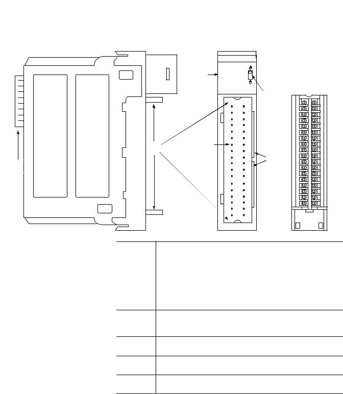
1756-HSC Parts Illustration
|
4 |
|
7 |
|
5 |
2 |
3 |
|
|
1 |
6 |
|
|
|
41623 |
Item |
Description |
|
|
1 |
Backplane connector - The backplane interface for the ControlLogix |
|
system connects the module to the backplane. |
|
|
2 |
Top and bottom guides - Guides provide assistance in seating the |
|
removable terminal block (RTB) onto the module. |
|
|
3 |
Connector pins - Input/output, power, and grounding connections are |
|
made to the module through these pins with the use of an RTB. |
4Status indicators - Indicators display the status of communication, module health, and presence of input/output devices. Use these indicators to help in troubleshooting.
5Locking tab - The locking tab anchors the RTB on the module, maintaining wiring connections.
6Slots for keying - The slots let you mechanically key the RTB to prevent inadvertently making the wrong wire connections to your module.
7Removable terminal block - The RTB lets you connect and house the wiring. There are several types of RTBs.
See page 46 for details on RTB types.
Rockwell Automation Publication 1756-UM007C-EN-P - November 2011

16 1756-HSC Module Features
Notes:
Rockwell Automation Publication 1756-UM007C-EN-P - November 2011

Chapter 2
Counter Modes
Introduction
Counter/Encoder Overview
This chapter describes the Counter modes for the 1756-HSC/B module. Topics include:
•types of counting: counter and encoder.
•means of storing the counts.
•modes for manipulating the count.
•tags for control of on-board outputs.
Topic |
Page |
|
|
Counter Mode |
19 |
|
|
Encoder Mode |
20 |
|
|
Preset |
22 |
|
|
Rollover |
22 |
|
|
Input Z (Gate/Reset) |
23 |
|
|
Outputs |
26 |
|
|
There are three Counter modes that can be selected from the Operational Mode pull-down menu on the Counter Configuration tab.
See Chapter 5 for configuration details.
The choices are:
•Counter mode (default).
•Encoder x1 mode.
•Encoder x4 mode.
The Encoder and Counter modes are virtually identical; the only difference is the method used to count. There are two counters (using input A and B) per module. Input Z, which is described in more detail later in this chapter, basically affects how the counts are stored based on the selected Storage mode.
In Counter mode, the module reads incoming pulses from input A only and stores the accumulated count value in the Present Value tag. The state of input B determines whether to increment or decrement the count based on whether it’s low, floating (count up) or high (count down).
In both Encoder modes, the 1756-HSC module uses two channels to read incoming pulses. The module uses the phase relationship between
inputs A and B to determine the count value and direction of the rotation.
Rockwell Automation Publication 1756-UM007C-EN-P - November 2011
18 Counter Modes
•Encoder x1This is a Bidirectional Count mode, counting up or down, using an incremental encoder with direction output.
•Encoder x4 - This is a Bidirectional Count mode, using quadrature encoder signals, with four times the resolution of X1.
The 1756-HSC/B module also offers the convenience of showing directional frequency by using any Counter mode. If the count value is increasing, the frequency is positive in the Totalizer tag. If the count value is decreasing, the frequency is negative in the Totalizer tag.
Where Count Values are Stored in Tags
Mode Description |
Present Value Tag |
Stored Value Tag |
Totalizer Tag |
|
|
|
|
Counter |
|
|
|
|
|
|
|
Encoder x1 |
Accumulated Count |
Stored Value |
Directional Frequency |
Encoder x4
There are several methods for using and manipulating the count values. Based on the state of the Z-input, the 1756-HSC module provides four modes of behavior if the application requires storage of the accumulated count value.
•Store and Continue Mode
•Store, Wait, and Resume
•Store and Reset, Wait, and Start
•Store and Reset, and Start
In addition, the 1756-HSC module features two software-configurable tags that provide control of the starting and ending points of an accumulated count sequence. These are the tags:
•Preset
•Rollover
The remainder of this chapter details each mode and the different configurations that you can use for specific needs of your 1756-HSC/B module.
Rockwell Automation Publication 1756-UM007C-EN-P - November 2011
Counter Modes |
19 |
|
|
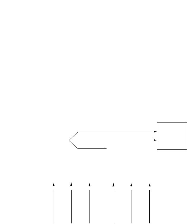
Counter Mode
This is the 1756-HSC module’s default operational mode that counts incoming pulses using input A. You can control the starting and ending points of the accumulated count depending on how you have configured the module.
In the Counter mode, the count increases or decreases based on the state of input B, which can be a random signal. If input B is high, the counter will count down. If input B is low or floating (that is, not connected to a voltage source), the counter counts up. Counting is done on the leading-edge of input A.
Input B |
Direction of Counter |
|
|
High |
Down |
|
|
Low or floating (not connected) |
Up |
|
|
Input Z is used in Counter mode only if a Store Count mode is enabled.
See page 23 for details on the Storage modes.
Counter Mode
|
|
|
|
|
|
|
|
|
|
|
|
|
|
|
|
|
Pulse Count |
|
|
|
|
|
|
Input A |
||||||
|
|
|
|
|
|
|
|
|
|
|
|
|
|
|
|
|
Increment/Decrement Count |
|
|
|
||||||||||
|
|
|
|
|
|
|
|
|
|
|
|
|
|
|
|
|
|
|
|
Input B |
||||||||||
|
|
|
|
|
|
|
|
|
|
|
|
|
|
|
|
|
|
|
||||||||||||
|
|
|
|
|
|
|
|
|
|
|
|
|
|
|
|
|
|
|
|
|
|
|
|
|
|
|||||
|
|
|
|
|
|
|
|
|
|
|
|
|
|
|
|
|
Input Z (optional) |
|
|
|||||||||||
|
|
|
|
|
|
|
|
|
|
|
|
|
|
|
|
|
|
|
|
|
|
|
|
|
||||||
|
|
|
|
|
|
|
|
|
|
|
|
|
|
|
|
|
|
|
|
|
|
|
|
|
||||||
|
Single-phase Pulse Generator |
|
|
|
|
|
|
|
|
|
|
|
|
1756-HSC Module |
||||||||||||||||
|
|
|
|
|
|
|
|
|
|
Count Up |
|
|
|
|
|
|
Count Down |
|
|
|
|
|
|
|
|
|||||
Input A |
|
|
|
|
|
|
|
|
|
|
|
|
|
|
|
|
|
|
|
|
|
|
|
|
|
|
|
|
||
|
|
|
|
|
|
|
|
|
|
|
|
|
|
|
|
|
|
|
|
|
|
|
|
|
|
|
|
|||
|
|
|
|
|
|
|
|
|
|
|
|
|
|
|
|
|
|
|
|
|
|
|
|
|
|
|
|
|
|
|
|
|
|
|
|
|
|
|
+ |
|
|
|
|
|
|
|
|
|
– |
|
|
|
|
|
|
|
|
|
|
|
|
Input B |
|
|
|
|
|
|
|
|
|
|
|
|
|
|
|
|
|
|
|
|
|
|
|
|
|
|
|
|||
|
|
|
|
|
|
|
|
|
|
|
|
|
|
|
|
|
|
|
|
|
|
|
|
|
|
|
|
|||
Accumulated Count |
|
|
|
|
|
|
|
|
|
|
|
|
|
|
|
|
|
|
|
|
|
|
|
|
|
|
|
|
|
|
|
... |
|
|
1 |
|
2 |
|
|
3 |
|
2 |
|
1 |
|
0 |
|
|
... |
|
|
|
|
||||||||
in Present Value Tag |
|
|
|
|
|
|
|
|
|
|
|
|
|
|
|
|||||||||||||||
|
|
|
|
|
|
|
|
|
|
|
|
|
|
|
|
|
|
|
|
|
|
|
|
|
|
|
|
|
||
Directional Frequency |
|
|
|
|
|
|
|
|
|
|
|
|
|
|
|
|
|
|
|
|
|
|
|
|
|
|
|
|
||
|
|
|
|
|
Positive Frequency |
|
|
|
|
|
|
Negative Frequency |
|
|
|
|
|
|
||||||||||||
in Totalizer Tag |
|
|
|
|
|
|
|
|
|
|
|
|
|
|
|
41688 |
||||||||||||||
|
|
|
|
|
|
|
|
|
|
|
|
|
|
|
|
|
|
|
|
|
|
|
|
|
|
|||||
Rockwell Automation Publication 1756-UM007C-EN-P - November 2011
20 Counter Modes
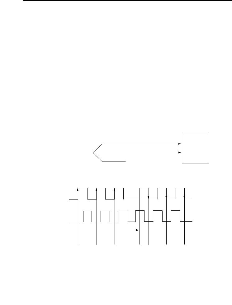
Encoder Mode
Encoder mode also counts incoming pulses. However, the phase relationship between two input channels (A and B) determines whether the direction of the count is up or down.
In Encoder x1 mode, an increasing count results when channel B is 90° ahead of channel A. The count is initiated on the rising edge of channel A, and the direction of the encoder is clockwise (positive).
The module produces a decreasing count when channel A is 90° ahead of channel B. The count is initiated on the falling edge of channel A, and the direction is counterclockwise (negative).
By monitoring both the number of pulses and the phase relationships of signals A and B, you can accurately determine the position and direction of the rotation.
The illustration shows the phase relationships between channels A and B for the x1 mode. Input Z is used in Encoder mode only if a Store Count mode is enabled. See page 23 for details on the Storage modes.
Encoder x1 Mode
Input A
|
|
|
|
|
Input A |
|
|
|
|||
|
|
|
|
Input B |
|
|
|
|
|||
|
|
|
|
|
Input B |
|
|
|
|||
|
|
|
|
|
|
|
|
|
|
Input Z (optional) |
|
|
|
|
|
||
|
|
Encoder |
|
|
1756-HSC Module |
|
|
|
|
|
|
B Leads A 90° A Leads B 90°
Input A
Input B
Accumulated Count |
|
|
|
|
Change |
|
|
|
|
|
|
|
||
|
|
|
|
|
|
|
|
|
|
|
||||
|
|
|
|
|
|
|
|
|
|
|
|
|
|
|
1 |
2 |
|
3 |
|
. . . |
2 |
|
1 |
|
0 |
|
|||
in Present Value Tag |
|
|
|
|
|
|||||||||
|
|
|
|
|
|
|
|
|
|
|
|
|
|
|
Directional Frequency |
|
|
|
|
|
|
|
|
|
|
|
|
|
|
|
|
|
|
|
|
|
|
|
|
|
|
|
|
|
|
Positive Frequency |
|
|
|
|
|
|
Negative Frequency |
|
|
||||
in Totalizer Tag |
|
|
|
|
|
|
|
|
44889 |
|||||
|
|
|
|
|
|
|
|
|
|
|
|
|
||
Rockwell Automation Publication 1756-UM007C-EN-P - November 2011
Counter Modes |
21 |
|
|
Encoder x4
Encoder x4 mode is identical to x1, except this mode counts on the leading and trailing edges of A and B to provide a greater number of pulse counts. The greater the number of pulse counts the better the module can
determine position.
Input Z is used in Encoder mode only if a Store Count mode is enabled.
See page 23 for details on the storage modes.
Encoder x4 Mode
Input A
Input A
Input B
Input B
Input Z (optional)
Quadrature Encoder
1756-HSC Module
B Leads A 90° |
A Leads B 90° |
Input A
Input B
Accumulated Count |
1 |
2 |
3 |
4 |
5 |
6 |
7 |
8 |
9 |
10 |
11 |
12 |
11 |
10 |
9 |
8 |
7 |
6 |
5 |
4 |
3 |
2 |
1 |
0 |
|
in Present Value Tag |
|
||||||||||||||||||||||||
|
|
|
|
|
|
|
|
|
|
|
|
|
|
|
|
|
|
|
|
|
|
|
|
|
|
Directional Frequency |
|
|
|
|
|
|
|
|
|
|
|
|
|
|
|
|
|
|
|
|
|
|
|
|
|
|
|
|
|
|
|
|
|
|
|
|
|
|
|
|
|
|
|
|
|
|
|
|
|
|
|
|
|
|
Positive Frequency |
|
|
|
|
|
|
Negative Frequency |
|
|
|
41689 |
|||||||||||
in Totalizer Tag |
|
|
|
|
|
|
|
|
|
|
|
|
|||||||||||||
|
|
|
|
|
|
|
|
|
|
|
|
|
|
|
|
|
|
|
|
|
|
|
|
||
|
|
|
|
|
|
|
|
|
|
|
|
|
|
|
|
|
|
|
|
|
|
|
|
|
|
Maximum frequency in Encoder x1 and x4 modes = 250 kHz (assuming 50% duty cycle), with a minimum pulse width at this frequency of 2 s. The module assumes a 90° phase (A/B°) difference between channels.
Rockwell Automation Publication 1756-UM007C-EN-P - November 2011

22 Counter Modes
Preset
Each of the two counters has one preset value associated with it. In the Encoder or Counter modes, the preset value represents a reference point (or value) from which the module begins counting. The module can count either up or down from the preset value.
The preset value itself is entered during module configuration. However, you must enter a preset command from either the RSLogix 5000 programming software or ladder logic before it becomes active. Setting the Preset Enable Bit in the Output tag to ‘1’ will send the preset value to the Present Value tag.
Preset values are entered on the Counter Configuration tab of the Module Properties dialog box.
See page 65 for an example of the Counter Configuration tab.
Preset in Output tag
When using the HSC Data-extended Comm Format while configuring the module, the Preset tag will be found in both the Configuration and Output tag areas.
The Configuration tag value is populated during software configuration with the Logix5000 controller, and sent to the module upon powerup, defining its behavior. This value will continue to define module behavior as long as the corresponding tag in the output area is zero.
If the value of the Preset tag in the output area is changed to a non-zero value, the module will disregard the value sent from the configuration area and use the value in the output area instead. This facilitates easier real-time ‘on-the-fly’ changes to the preset function.
Rollover
Each of the two counters has one rollover value associated with it. When the accumulated count value in the Rollover tag reaches the rollover value, it resets to zero (0) and begins counting again. The rollover value is circular (for example, if the rollover value = 360, the count will be from 358, 359, 0, 1, and so forth, in a positive direction and from 1, 0, 359, 358, and so forth, in a negative direction).
Rollover values are entered on the Counter Configuration tab of the Module Properties dialog box in the RSLogix 5000 programming software or can be changed in ladder logic.
See page 65 for an example of the Counter Configuration tab.
Rockwell Automation Publication 1756-UM007C-EN-P - November 2011

Counter Modes |
23 |
|
|
Rollover in Output tag
When using the HSC Data-extended Comm Format while configuring the module, the Rollover tag will be found in both the Configuration and Output tag areas.
The Configuration tag value is populated during software configuration with the Logix5000 controller, and sent to the module upon powerup, defining its behavior. This value will continue to define module behavior as long as the corresponding tag in the Output area is zero.
If the value of the Rollover tag in the Output area is changed to a non-zero value, the module will disregard the value sent from the Configuration area and use the value in the Output area instead. This facilitates easier real-time ‘on-the-fly’ changes to the Rollover function.
Input Z (Gate/Reset)
Input Z, when active, will change the behavior of an accumulated count value in the Present Value tag, depending upon which of four modes is selected.
•Store and Continue Mode
•Store, Wait, and Resume
•Store and Reset, Wait, and Start
•Store and Reset, and Start
The Storage modes are selected on the Counter Configuration tab on the
Module Properties dialog box of the RSLogix 5000 programming software.
Storage Modes
The store count feature allows the module to store the current count value and follow four behavioral paths, depending on which Store mode is selected. The store count is triggered by the state of the Z-input (the gate) on the module.
|
The four modes can be changed while normal module operation |
|
IMPORTANT |
||
continues. Improper use of on-the-fly changes may cause |
||
|
||
|
||
|
unintended machine operation when the store count is used as |
|
|
a trigger for machine sequencing. |
|
|
|
The following illustrations show how the different modes store count values in the Present Value and Stored Value tags.
Rockwell Automation Publication 1756-UM007C-EN-P - November 2011
24 Counter Modes
Store and Continue Mode
Incoming Pulses |
|
10 |
|
11 |
12 |
|
13 |
14 |
15 |
16 |
17 |
18 |
19 |
20 |
|
|
|||
|
|
|
|
|
|||||||||||||||
|
|
|
|
|
|
|
|
|
|
|
|
|
|
|
|
|
|||
|
|
|
|
|
|
|
|
|
|
|
|
|
|
|
|
|
|
|
|
Present Value Tag |
|
...10 |
|
11 |
12 |
|
13 |
14 |
15 |
16 |
17 |
18 |
19 |
20 |
|
|
|||
in Logix Controller |
|
|
|
|
|
|
|
|
|
|
|
|
|
|
|
|
|
|
|
|
|
|
|
|
|
|
|
|
|
|
|
|
|
|
|
|
|
|
|
Z-Input |
|
|
|
|
|
|
|
|
|
|
|
|
|
|
|
|
|
|
|
|
|
|
|
|
|
|
|
|
|
|
|
|
|
|
|
|
|
||
Stored Value Tag |
|
|
|
|
|
|
|
|
|
|
|
|
|
|
|
||||
... |
|
8 |
8 |
|
13 |
13 |
13 |
13 |
13 |
18 |
18 |
18 |
|
|
|||||
in Logix Controller |
|
|
|
|
|
|
|
|
|
|
|
|
|
|
|
|
44900 |
||
|
|
|
|
|
|
|
|
|
|
|
|
|
|
|
|
||||
In the Store and Continue mode, the module:
•reads the Present Value and places it into the Stored Value on the leading edge of Input Z.
•continues to accumulate the Present Value based on presets and incoming pulses.
•retains the Stored Value until it is overwritten by new data from the next leading edge of a pulse on Input Z.
Store, Wait, and Resume
Incoming Pulses |
10 |
|
11 |
12 |
|
13 |
14 |
15 |
16 |
17 |
18 |
19 |
20 |
|
|
||||||||||||
Present Value Tag |
|
|
|
|
|
|
|
|
|
|
|
|
|
|
|
|
|
|
|
|
|
|
|
|
|
|
|
10 |
11 |
11 |
11 |
12 |
13 |
14 |
14 |
14 |
15 |
16 |
|||
in Logix Controller |
|
|
|
|
|
|
|
|
|
|
|
|
|
|
|
|
|
|
|
|
|
|
|
|
|
|
|
Z-Input |
|
|
|
|
|
|
|
|
|
|
|
|
|
|
|
|
|
|
|
|
|
|
|
|
|
|
|
|
|
|
|
|
|
|
|
||
|
|
|
|
|
|
|
|
|
|
|
|
|
|
|
|
|
||
Stored Value Tag |
|
|
|
|
|
|
|
|
|
|
|
|
|
|
||||
|
... |
11 |
11 |
11 |
11 |
11 |
14 |
14 |
14 |
14 |
14 |
|
44901 |
|||||
in Logix Controller |
|
|
|
|
|
|
|
|
|
|
|
|
|
|
|
|
||
|
|
|
|
|
|
|
|
|
|
|
|
|
|
|
|
|
|
|
In the Store, Wait and Resume mode, the module:
•reads the Present Value and places it into the Stored Value on the leading edge of Input Z.
•stops accumulating the count in the Present Value as long as the Z-input is high.
•resumes accumulating the count in the Present Value when the Z-input goes low.
•retains the Stored Value until it is overwritten by new data from the next leading edge of a pulse on Input Z.
Rockwell Automation Publication 1756-UM007C-EN-P - November 2011
Counter Modes |
25 |
|
|
Store and Reset, Wait, and Start
Incoming Pulses |
10 |
|
11 |
12 |
|
13 |
14 |
15 |
16 |
17 |
18 |
19 |
20 |
|
|
||||||||||||
|
|
|
|
|
|
|
|
|
|
|
|
|
|
Present Value Tag |
|
|
|
|
|
|
|
|
|
|
|
|
|
10 |
|
11 0 |
0 |
|
0 |
1 |
2 |
3 0 |
0 |
0 |
1 |
2 |
|
in Logix Controller |
|
|
|
|
|
|
|
|
|
|
|
|
|
|
|
|
|
|
|
|
|
|
|
|
|
|
Z-Input |
|
|
|
|
|
|
|
|
|
|
|
|
|
|
|
|
|
|
|
|
|
|
|
|
|
|
|
|
|
|
|
|
|
|
|
||
Stored Value Tag |
|
|
|
|
|
|
|
|
|
|
|
|
|
|
|
|
|
|
|
... |
11 |
11 |
11 |
11 |
11 |
3 |
3 |
3 |
|
3 |
3 |
|
44902 |
||||
in Logix Controller |
|
|
|
|||||||||||||||
|
|
|
|
|
|
|
|
|
|
|
|
|
|
|
|
|
||
|
|
|
|
|
|
|
|
|
|
|
|
|
|
|
|
|
|
|
|
|
|
|
|
|
|
|
|
|
|
|
|
|
|
|
|
|
|
|
|
|
|
|
|
|
|
|
|
|
|
|
|
|
|
|
|
|
In the Store and Reset, Wait, and Start mode, the module:
•reads the Present Value and places it into the Stored Value on the leading edge of Input Z and resets the count to zero (0) in the Present Value.
•resumes normal counting from zero (0) after the Z-Input goes low.
•retains the Stored Value until it is overwritten by new data from the next leading edge of a pulse on Input Z.
Store and Reset, and Start
Incoming Pulses |
10 |
11 |
12 |
13 |
14 |
15 |
16 |
17 |
18 |
19 |
20 |
|
|
|
|
|
|
|
|
|
|
|
|
Present Value Tag |
|
|
|
|
|
|
|
|
|
|
|
10 |
11 0 |
1 |
2 |
3 |
4 |
5 0 |
1 |
2 |
3 |
4 |
|
in Logix Controller |
|
|
|
|
|
|
|
|
|
|
|
|
|
|
|
|
|
|
|
|
|
|
Z-Input |
|
|
|
|
|
|
|
|
|
|
|
|
|
|
|
|
|
|
|
|
|
|
|
|
|
|
|
|
|
|
|
|
|
|
|
||
Stored Value Tag |
|
|
|
|
|
|
|
|
|
|
|
|
|
|
|
|
|
|
|
... |
11 |
11 |
11 |
|
11 |
11 |
5 |
|
5 |
5 |
|
5 |
5 |
|
44903 |
||
in Logix Controller |
|
|
|
|
|
|
|
|
|
|
|
|
|
|
|
|
||
|
|
|
|
|
|
|
|
|
|
|
|
|
|
|
|
|
|
|
In the Store and Reset, and Start mode, the module:
•reads the Present Value and places it into the Stored Value on the leading edge of Input Z and resets the count to zero (0) in Present Value.
•resumes counting from zero (0) regardless of the state of the Z-input.
•retains the Stored Value until it is overwritten by new data from the next leading edge of a pulse on Input Z.
Rockwell Automation Publication 1756-UM007C-EN-P - November 2011

26 Counter Modes
Outputs
|
You have the option of selecting either the rising or falling edge |
|
IMPORTANT |
||
of the gate/reset pulse. When the Invert Z Value box is checked |
||
|
||
|
||
|
on the Counter Configuration tab, the state of the Z input is |
|
|
reversed as illustrated in the four Store modes. |
For example, in the Store and Reset, and Start mode using the Invert Z, the falling edge of the pulse on Input Z will store the count value in the Stored Value tag and reset the Present Value tag to zero. The counter continues to count while the gate pin is low or high, but the present value is reset to zero (0) on the next falling edge of Input Z.
The module has four outputs, isolated in pairs (0 and 1, 2 and 3). Each output is capable of sourcing current from an externally supplied voltage up to
30V DC. You must connect an external power supply to each of the output pairs. The outputs can source 1 A DC and are hardware-driven. They turn On or Off in less than 50 s when the appropriate count value has been reached.
Assign Outputs to Counters
By using configuration tags or the RSLogix 5000 software defaults, you can assign the outputs on the module to any of the various counters. You can assign as many as two outputs to a given counter. However, an output may be assigned only once to a counter; it’s not possible to use the same output with two different counters.
Each output on the 1756-HSC module can be turned On and Off at your discretion. The operation of outputs tied to a counter (on the Output Configuration tab of the Module Properties dialog box) are performed independently from the controller scans.
Output Operation
When the outputs for the module are enabled and assigned to a counter, they operate in an On-Off fashion. Up to two On-Off windows may be used for each output. The outputs use a comparison of the Present Value to the values you have programmed in one or both of the following tags:
•First Value Output Turns On and First Value Output Turns OFF
•Second Value Output Turns ON and Second Value Output Turns OFF
Rockwell Automation Publication 1756-UM007C-EN-P - November 2011
Counter Modes |
27 |
|
|
Accumulated Count
in Present Value Tag
For example, the ‘Output Turns ON’ tag is set for a value of 2000 and the ‘Output Turns OFF’ tag is set for a value of 5000.
2001…4999
5000
2000
10686
In the illustration, the:
•output turns On at the Present Value of 2000.
•output remains energized for 3000 additional counts.
•output turns Off at the Present Value of 5000.
Tying Outputs to Counters
You can jumper any of the outputs to any of the counter inputs on the module’s RTB. In this way, it is possible to use the outputs to reset a counter or to cascade counters. If using the outputs this way, make certain that the correct input terminals are used to interface with the appropriate output voltage.
Rockwell Automation Publication 1756-UM007C-EN-P - November 2011

28 Counter Modes
Notes:
Rockwell Automation Publication 1756-UM007C-EN-P - November 2011

Chapter 3
Introduction
Frequency Overview
Frequency Modes
This chapter describes the frequency modes that are available with the 1756-HSC/B module when using the HSC Data-extended
Comm Format.
The Frequency modes are:
•Frequency - number of input pulses per user-defined time interval.
•Period Rate - number of sampled, internal 4 MHz pulses per user-defined number of incoming pulses, with outputs updated at the end of the sample period with the Present Value, Totalizer, and Stored Value tags.
•Continuous Rate - number of sampled, internal 4 MHz pulses per user-defined number of incoming pulses, with outputs updated throughout the sample period. The Present Value, Totalizer, and Stored Value tags are updated only at the end of the sample period.
Topic |
Page |
|
|
Frequency Mode |
30 |
|
|
Period Rate and Continuous Rate Modes |
32 |
|
|
Output Operation |
35 |
|
|
Period Rate /Continuous Rate Output Examples |
36 |
|
|
Each of the three Frequency modes use incoming pulse counts in a user-defined interval to determine frequency values. The Stored Value tag contains the calculated frequency and is always positive.
You can select one of three Frequency-operational modes based on the frequency of the incoming signal. Frequency mode is best suited for calculating higher frequencies because you define the sample period used to count incoming pulses. At higher frequencies, there are a greater number of pulses to be sampled that results in the ability to calculate frequency at a higher resolution. The Stored Value tag is updated at the end of the selected sample period.
Period Rate and Continuous Rate modes use an internal 4 MHz clock and a user-defined number of incoming pulses configured by the Scaler value that results in better performance at lower frequencies, where more 4 MHz pulses are accumulated. Higher Scaler values also help to improve the calculation of high frequency signals as longer pulse durations provide for more 4 MHz pulses to be counted. Therefore, the combination of the Scaler and incoming frequency determines the rate at which the frequency is updated in the Stored Value tag.
Rockwell Automation Publication 1756-UM007C-EN-P - November 2011

30 Frequency Modes
The difference between the Period Rate and Continuous Rate modes is the outputs are dynamic (On/Off) throughout the sample period for Continuous Rate while Period Rate outputs are updated only at the end of the sample period. Your desired output behavior should determine whether one uses Period Rate or Continuous Rate modes.
See page 35 for details.
Where Frequency Values are Stored in Tags
Mode Description |
Present Value Tag |
Stored Value Tag |
Totalizer Tag |
|
|
|
|
|
|
Frequency |
No. of input pulses occurring |
|
|
|
|
in Sample Period |
Frequency |
Accumulated pulse count |
|
|
|
|||
Period Rate Frequency |
No. of 4 MHz pulses occurring |
|||
|
|
|||
Continuous Rate Frequency |
in Sample Period |
|
|
|
|
|
|
||
|
|
|
|
Frequency Mode
In Frequency mode, the module counts incoming pulses on channel A for a user-specified time interval that is configured in the Scaler tag. At the end of the interval, the module returns a value representing the sampled number of pulses in the Present Value tag, a value indicating the incoming frequency in the Stored Value tag and a value indicating the total number of pulses that have occurred in the Totalizer tag.
When the count and frequency are updated at the end of the sample period, any associated outputs are checked against their associated presets. The output On/Off values are related to the value in the Stored Value tag.
As you increase the Scaler (see Sample Period for Frequency Mode), the accuracy of the frequency and the time between samples will increase. In general, if you are measuring a higher frequency, the Scaler can be small. If you are measuring a lower frequency, the Scaler likely will be larger.
EXAMPLE |
Frequency = No. of pulses per sample period/Scaler Time. |
|
For example, if the frequency = 30 Hz, and the Scaler = 100 ms, then |
||
|
||
|
||
|
the Present Value tag returned = 3, and the Stored Value tag = 30. |
|
|
|
Preset and rollover tag settings are active in this Frequency mode. User-defined preset and rollover commands provide control of the starting and ending points of incoming pulses, thus affecting the values in the Totalizer tag.
See page 22 in Chapter 2 for preset and rollover tag details.
Rockwell Automation Publication 1756-UM007C-EN-P - November 2011
Loading...