


 Loading...
PowerFlex 1203-USB Converter
Firmware Revision 1.xxx
User Manual

Important User Information Solid state equipment has operational characteristics differing from those of electromechanical equipment. Safety Guidelines for the Application,
Installation and Maintenance of Solid State Controls (Publication SGI-1.1 available from your local Rockwell Automation sales office or online at http:// www.rockwellautomation.com/literature) describes some important differences
between solid state equipment and hard-wired electromechanical devices. Because of this difference, and also because of the wide variety of uses for solid state equipment, all persons responsible for applying this equipment must satisfy themselves that each intended application of this equipment is acceptable.
In no event will Rockwell Automation, Inc. be responsible or liable for indirect or consequential damages resulting from the use or application of this equipment.
The examples and diagrams in this manual are included solely for illustrative purposes. Because of the many variables and requirements associated with any particular installation, Rockwell Automation, Inc. cannot assume responsibility or liability for actual use based on the examples and diagrams.
No patent liability is assumed by Rockwell Automation, Inc. with respect to use of information, circuits, equipment, or software described in this manual.
Reproduction of the contents of this manual, in whole or in part, without written permission of Rockwell Automation, Inc. is prohibited.
Throughout this manual, when necessary we use notes to make you aware of safety considerations.
WARNING: Identifies information about practices or
! |
circumstances that can cause an explosion in a hazardous |
|
|
|
environment, which may lead to personal injury or death, property |
|
damage, or economic loss. |
|
|
Important: Identifies information that is critical for successful application and understanding of the product.
ATTENTION: Identifies information about practices or
! |
circumstances that can lead to personal injury or death, property |
|
|
|
damage, or economic loss. Attentions help you identify a hazard, |
|
avoid a hazard, and recognize the consequences. |
|
|
Shock Hazard labels may be located on or inside the equipment (e.g., drive or motor) to alert people that dangerous voltage may be present.
Burn Hazard labels may be located on or inside the equipment (e.g., drive or motor) to alert people that surfaces may be at dangerous temperatures.
Allen-Bradley, Rockwell Automation, TechConnect, RSLogix, PowerFlex, Kinetix, SMC Flex, Connected Components Workbench,
DriveExplorer, and DriveExecutive are trademarks of Rockwell Automation, Inc.
Trademarks not belonging to Rockwell Automation are property of their respective companies.
PowerFlex 1203-USB Converter User Manual

Summary of Changes
The information below summarizes the changes made to this manual since its last release (September 2012):
Description of Changes |
Page |
|
|
In the ‘Components’ section, added information about the 2090-CCMUSDS-48AA0x cable |
1-2 |
required for use with Kinetix 3 drives. |
|
|
|
In the ‘Compatible Products’ section, added Kinetix 3 drives to the DSI Products subsection. |
1-4 |
|
|
In the ‘Quick Start’ section in step 2 for DSI drives, revised ‘sub-step a’ to include the |
1-6 |
2090-CCMUSDS-48AA0x cable required for use with Kinetix 3 drives. |
|
|
|
In Figure 1.2, added the 2090-CCMUSDS-48AA0x cable required for use with Kinetix 3 drives. |
1-7 |
|
|
In the ‘Connecting the Converter to a DSI Drive and the Computer’ subsection, added the |
2-3 |
2090-CCMUSDS-48AA0x cable required for use with Kinetix 3 drives. |
|
|
|
PowerFlex 1203-USB Converter User Manual
Publication DRIVES-UM001D-EN-P

soc-ii Summary of Changes
Notes:
PowerFlex 1203-USB Converter User Manual
Publication DRIVES-UM001D-EN-P

Table of Contents
Preface |
About This Manual |
|
|
Conventions Used in This Manual . . . . . . . . . . . . . . . . . . . . . . . . . . . . . . . . . . . . . . . . . . |
P-1 |
|
Rockwell Automation Support . . . . . . . . . . . . . . . . . . . . . . . . . . . . . . . . . . . . . . . . . . . . . |
P-1 |
|
Local Product Support . . . . . . . . . . . . . . . . . . . . . . . . . . . . . . . . . . . . . . . . . . . . . . . . |
P-1 |
|
Technical Product Assistance . . . . . . . . . . . . . . . . . . . . . . . . . . . . . . . . . . . . . . . . . . . |
P-1 |
|
Additional Resources . . . . . . . . . . . . . . . . . . . . . . . . . . . . . . . . . . . . . . . . . . . . . . . . . . . . |
P-2 |
Chapter 1 |
Getting Started |
|
|
Components. . . . . . . . . . . . . . . . . . . . . . . . . . . . . . . . . . . . . . . . . . . . . . . . . . . . . . . . . . . . |
1-2 |
|
Features . . . . . . . . . . . . . . . . . . . . . . . . . . . . . . . . . . . . . . . . . . . . . . . . . . . . . . . . . . . . . . . |
1-2 |
|
Compatible Products . . . . . . . . . . . . . . . . . . . . . . . . . . . . . . . . . . . . . . . . . . . . . . . . . . . . . |
1-3 |
|
DPI Products. . . . . . . . . . . . . . . . . . . . . . . . . . . . . . . . . . . . . . . . . . . . . . . . . . . . . . . . |
1-3 |
|
DSI Products. . . . . . . . . . . . . . . . . . . . . . . . . . . . . . . . . . . . . . . . . . . . . . . . . . . . . . . . |
1-4 |
|
SCANport Products . . . . . . . . . . . . . . . . . . . . . . . . . . . . . . . . . . . . . . . . . . . . . . . . . . |
1-4 |
|
Required Equipment . . . . . . . . . . . . . . . . . . . . . . . . . . . . . . . . . . . . . . . . . . . . . . . . . . . . . |
1-4 |
|
Equipment Shipped with the Converter . . . . . . . . . . . . . . . . . . . . . . . . . . . . . . . . . . . |
1-4 |
|
User-Supplied Equipment. . . . . . . . . . . . . . . . . . . . . . . . . . . . . . . . . . . . . . . . . . . . . . |
1-5 |
|
Safety Precautions. . . . . . . . . . . . . . . . . . . . . . . . . . . . . . . . . . . . . . . . . . . . . . . . . . . . . . . |
1-6 |
|
Quick Start . . . . . . . . . . . . . . . . . . . . . . . . . . . . . . . . . . . . . . . . . . . . . . . . . . . . . . . . . . . . |
1-6 |
Chapter 2 |
Installing the Converter |
|
|
Connecting the Cables. . . . . . . . . . . . . . . . . . . . . . . . . . . . . . . . . . . . . . . . . . . . . . . . . . . . |
2-1 |
|
Connecting the Converter to a DPI or SCANport Drive and the Computer. . . . . . . . |
2-2 |
|
Connecting the Converter to a DSI Drive and the Computer . . . . . . . . . . . . . . . . . . . |
2-3 |
|
Installing the USB Drivers . . . . . . . . . . . . . . . . . . . . . . . . . . . . . . . . . . . . . . . . . . . . . . . . |
2-4 |
|
Download Both USB Drivers to the Computer . . . . . . . . . . . . . . . . . . . . . . . . . . . . . |
2-4 |
|
Install Both USB Drivers . . . . . . . . . . . . . . . . . . . . . . . . . . . . . . . . . . . . . . . . . . . . . . |
2-4 |
|
Installing Connected Components Workbench Software . . . . . . . . . . . . . . . . . . . . . . . . |
2-12 |
|
Powering Up the Converter . . . . . . . . . . . . . . . . . . . . . . . . . . . . . . . . . . . . . . . . . . . . . . . |
2-12 |
|
Removing the Converter . . . . . . . . . . . . . . . . . . . . . . . . . . . . . . . . . . . . . . . . . . . . . . . . . |
2-13 |
Chapter 3 |
Configuring the Converter |
|
|
Configuration Tools. . . . . . . . . . . . . . . . . . . . . . . . . . . . . . . . . . . . . . . . . . . . . . . . . . . . . . |
3-1 |
|
Using Connected Components Workbench Software . . . . . . . . . . . . . . . . . . . . . . . . . . . . |
3-2 |
|
Resetting the Converter . . . . . . . . . . . . . . . . . . . . . . . . . . . . . . . . . . . . . . . . . . . . . . . . . . . |
3-7 |
|
Updating the Firmware . . . . . . . . . . . . . . . . . . . . . . . . . . . . . . . . . . . . . . . . . . . . . . . . . . . |
3-8 |
|
Using RTU Master Mode for a Serial Multi-drop Network . . . . . . . . . . . . . . . . . . . . . . . |
3-8 |
|
Network Wiring . . . . . . . . . . . . . . . . . . . . . . . . . . . . . . . . . . . . . . . . . . . . . . . . . . . . . |
3-8 |
|
Establishing Communication . . . . . . . . . . . . . . . . . . . . . . . . . . . . . . . . . . . . . . . . . . |
3-10 |
|
Configuring the Drive Parameters . . . . . . . . . . . . . . . . . . . . . . . . . . . . . . . . . . . . . . |
3-10 |
|
Configuring the Converter for RTU Master Mode . . . . . . . . . . . . . . . . . . . . . . . . . . |
3-11 |
|
Configuring RSLinx for Serial Multi-Drop System . . . . . . . . . . . . . . . . . . . . . . . . . |
3-12 |
|
Accessing Drives on the RTU Master (Serial Multi-drop) Network . . . . . . . . . . . . |
3-14 |
PowerFlex 1203-USB Converter User Manual
Publication DRIVES-UM001D-EN-P

ii Table of Contents
Chapter 4 |
Troubleshooting |
|
|
Understanding the Status Indicators . . . . . . . . . . . . . . . . . . . . . . . . . . . . . . . . . . . . . . . . . |
4-1 |
|
Diamond Status Indicator . . . . . . . . . . . . . . . . . . . . . . . . . . . . . . . . . . . . . . . . . . . . . . . . . |
4-2 |
|
RX Status Indicator . . . . . . . . . . . . . . . . . . . . . . . . . . . . . . . . . . . . . . . . . . . . . . . . . . . . . . |
4-2 |
|
TX Status Indicator . . . . . . . . . . . . . . . . . . . . . . . . . . . . . . . . . . . . . . . . . . . . . . . . . . . . . . |
4-2 |
|
Converter Diagnostic Items . . . . . . . . . . . . . . . . . . . . . . . . . . . . . . . . . . . . . . . . . . . . . . . . |
4-3 |
|
Diagnostic Items for DPI Drives . . . . . . . . . . . . . . . . . . . . . . . . . . . . . . . . . . . . . . . . . |
4-3 |
|
Diagnostic Items for DSI Drives . . . . . . . . . . . . . . . . . . . . . . . . . . . . . . . . . . . . . . . . . |
4-3 |
|
Diagnostic Items for SCANport Drives . . . . . . . . . . . . . . . . . . . . . . . . . . . . . . . . . . . |
4-3 |
|
Viewing Diagnostic Data . . . . . . . . . . . . . . . . . . . . . . . . . . . . . . . . . . . . . . . . . . . . . . . . . . |
4-4 |
|
Converter Events . . . . . . . . . . . . . . . . . . . . . . . . . . . . . . . . . . . . . . . . . . . . . . . . . . . . . . . . |
4-6 |
|
Event Codes for DPI Drives . . . . . . . . . . . . . . . . . . . . . . . . . . . . . . . . . . . . . . . . . . . . |
4-6 |
|
Event Codes for DSI Drives . . . . . . . . . . . . . . . . . . . . . . . . . . . . . . . . . . . . . . . . . . . . |
4-7 |
|
Event Codes for SCANport Drives |
|
|
(DriveExplorer or DriveExecutive software only) . . . . . . . . . . . . . . . . . . . . . . . . |
4-7 |
|
Viewing and Clearing Events. . . . . . . . . . . . . . . . . . . . . . . . . . . . . . . . . . . . . . . . . . . . . . . |
4-8 |
|
Viewing and Clearing DF1 Communication Statistics . . . . . . . . . . . . . . . . . . . . . . . . . . . |
4-9 |
|
Troubleshooting Potential Problems . . . . . . . . . . . . . . . . . . . . . . . . . . . . . . . . . . . . . . . . |
4-10 |
|
Unable to Establish Connection Between the Computer and Converter. . . . . . . . . . |
4-10 |
|
No Communication to the Drive . . . . . . . . . . . . . . . . . . . . . . . . . . . . . . . . . . . . . . . . |
4-10 |
|
Cannot Communicate with a SCANport-based Drive . . . . . . . . . . . . . . . . . . . . . . . |
4-10 |
Appendix A |
Specifications |
|
|
Communications . . . . . . . . . . . . . . . . . . . . . . . . . . . . . . . . . . . . . . . . . . . . . . . . . . . . . . . . |
A-1 |
|
Electrical . . . . . . . . . . . . . . . . . . . . . . . . . . . . . . . . . . . . . . . . . . . . . . . . . . . . . . . . . . . . . . |
A-1 |
|
Mechanical. . . . . . . . . . . . . . . . . . . . . . . . . . . . . . . . . . . . . . . . . . . . . . . . . . . . . . . . . . . . . |
A-1 |
|
Environmental . . . . . . . . . . . . . . . . . . . . . . . . . . . . . . . . . . . . . . . . . . . . . . . . . . . . . . . . . . |
A-2 |
|
Agency Certification . . . . . . . . . . . . . . . . . . . . . . . . . . . . . . . . . . . . . . . . . . . . . . . . . . . . . |
A-2 |
Appendix B |
Converter Parameters |
|
|
Parameters – DPI Drives . . . . . . . . . . . . . . . . . . . . . . . . . . . . . . . . . . . . . . . . . . . . . . . . . . |
B-1 |
|
Parameters – DSI Drives . . . . . . . . . . . . . . . . . . . . . . . . . . . . . . . . . . . . . . . . . . . . . . . . . . |
B-2 |
|
Parameters – SCANport Drives (DriveExplorer or DriveExecutive software only) . . . . . |
B-4 |
Appendix C |
Use with DriveExplorer Software |
|
|
Installing DriveExplorer Software. . . . . . . . . . . . . . . . . . . . . . . . . . . . . . . . . . . . . . . . . . . |
C-1 |
|
Configuring the Converter . . . . . . . . . . . . . . . . . . . . . . . . . . . . . . . . . . . . . . . . . . . . . . . . . |
C-2 |
|
Resetting the Converter . . . . . . . . . . . . . . . . . . . . . . . . . . . . . . . . . . . . . . . . . . . . . . . . . . . |
C-4 |
|
Preparing for a Firmware Update . . . . . . . . . . . . . . . . . . . . . . . . . . . . . . . . . . . . . . . . . . . |
C-4 |
|
Updating the Firmware . . . . . . . . . . . . . . . . . . . . . . . . . . . . . . . . . . . . . . . . . . . . . . . . . . . |
C-5 |
|
Troubleshooting . . . . . . . . . . . . . . . . . . . . . . . . . . . . . . . . . . . . . . . . . . . . . . . . . . . . . . . . . |
C-5 |
|
Viewing Diagnostic Data . . . . . . . . . . . . . . . . . . . . . . . . . . . . . . . . . . . . . . . . . . . . . . |
C-5 |
|
Viewing and Clearing Events . . . . . . . . . . . . . . . . . . . . . . . . . . . . . . . . . . . . . . . . . . . |
C-6 |
|
Viewing and Clearing DF1 Communication Statistics . . . . . . . . . . . . . . . . . . . . . . . . |
C-7 |
|
Using RTU Master Mode for a Serial Multi-drop Network . . . . . . . . . . . . . . . . . . . . . . . |
C-8 |
|
Network Wiring. . . . . . . . . . . . . . . . . . . . . . . . . . . . . . . . . . . . . . . . . . . . . . . . . . . . . . |
C-8 |
|
Establishing Communication . . . . . . . . . . . . . . . . . . . . . . . . . . . . . . . . . . . . . . . . . . . |
C-8 |
|
Configuring the Drive Parameters. . . . . . . . . . . . . . . . . . . . . . . . . . . . . . . . . . . . . . . . |
C-8 |
|
Configuring the Converter for RTU Master Mode . . . . . . . . . . . . . . . . . . . . . . . . . . . |
C-9 |
|
Accessing Drives on the RTU Master (Serial Multi-drop) Network. . . . . . . . . . . . . . |
C-9 |
PowerFlex 1203-USB Converter User Manual
Publication DRIVES-UM001D-EN-P

Table of Contents |
iii |
|
|
Appendix D Use with DriveExecutive Software
Installing DriveExecutive Software. . . . . . . . . . . . . . . . . . . . . . . . . . . . . . . . . . . . . . . . . . D-1 Configuring the Converter. . . . . . . . . . . . . . . . . . . . . . . . . . . . . . . . . . . . . . . . . . . . . . . . . D-2 Resetting the Converter . . . . . . . . . . . . . . . . . . . . . . . . . . . . . . . . . . . . . . . . . . . . . . . . . . . D-6 Preparing for a Firmware Update . . . . . . . . . . . . . . . . . . . . . . . . . . . . . . . . . . . . . . . . . . . D-6 Updating the Firmware . . . . . . . . . . . . . . . . . . . . . . . . . . . . . . . . . . . . . . . . . . . . . . . . . . . D-7 Troubleshooting . . . . . . . . . . . . . . . . . . . . . . . . . . . . . . . . . . . . . . . . . . . . . . . . . . . . . . . . D-7
Viewing Diagnostic Data . . . . . . . . . . . . . . . . . . . . . . . . . . . . . . . . . . . . . . . . . . . . . . D-7 Viewing and Clearing Events . . . . . . . . . . . . . . . . . . . . . . . . . . . . . . . . . . . . . . . . . . . D-8 Viewing and Clearing DF1 Communication Statistics. . . . . . . . . . . . . . . . . . . . . . . . D-9 Using RTU Master Mode for a Serial Multi-drop Network . . . . . . . . . . . . . . . . . . . . . . D-10 Network Wiring . . . . . . . . . . . . . . . . . . . . . . . . . . . . . . . . . . . . . . . . . . . . . . . . . . . . D-10 Establishing Communication . . . . . . . . . . . . . . . . . . . . . . . . . . . . . . . . . . . . . . . . . . D-10 Configuring the Drive Parameters . . . . . . . . . . . . . . . . . . . . . . . . . . . . . . . . . . . . . . D-10 Configuring the Converter for RTU Master Mode . . . . . . . . . . . . . . . . . . . . . . . . . . D-11 Configuring RSLinx for Serial Multi-Drop . . . . . . . . . . . . . . . . . . . . . . . . . . . . . . . D-11 Accessing Drives on the RTU Master (Serial Multi-drop) Network . . . . . . . . . . . . D-14
Appendix E Use with HyperTerminal Software
Configuring the Converter. . . . . . . . . . . . . . . . . . . . . . . . . . . . . . . . . . . . . . . . . . . . . . . . . E-1 Navigating with Terminal Emulation Software . . . . . . . . . . . . . . . . . . . . . . . . . . . . . E-4 Resetting the Converter . . . . . . . . . . . . . . . . . . . . . . . . . . . . . . . . . . . . . . . . . . . . . . . . . . . E-4 Preparing for a Firmware Update . . . . . . . . . . . . . . . . . . . . . . . . . . . . . . . . . . . . . . . . . . . E-5 Updating Firmware . . . . . . . . . . . . . . . . . . . . . . . . . . . . . . . . . . . . . . . . . . . . . . . . . . . . . . E-5 Troubleshooting . . . . . . . . . . . . . . . . . . . . . . . . . . . . . . . . . . . . . . . . . . . . . . . . . . . . . . . . E-6 Viewing Diagnostic Data . . . . . . . . . . . . . . . . . . . . . . . . . . . . . . . . . . . . . . . . . . . . . . E-6 Viewing and Clearing Events . . . . . . . . . . . . . . . . . . . . . . . . . . . . . . . . . . . . . . . . . . . E-6 Viewing and Clearing DF1 Communication Statistics. . . . . . . . . . . . . . . . . . . . . . . . E-7
Appendix F History of Changes
DRIVES-UM001C-EN-P, September 2012 . . . . . . . . . . . . . . . . . . . . . . . . . . . . . . . . . . . F-1
DRIVES-UM001B-EN-P, October 2006 . . . . . . . . . . . . . . . . . . . . . . . . . . . . . . . . . . . . . F-1
Glossary
Index
PowerFlex 1203-USB Converter User Manual
Publication DRIVES-UM001D-EN-P

iv |
Table of Contents |
|
|
PowerFlex 1203-USB Converter User Manual
Publication DRIVES-UM001D-EN-P

Preface
About This Manual
Conventions Used in This
Manual
Rockwell Automation
Support
This manual provides the basic information needed to install, start up, and troubleshoot the PowerFlex 1203-USB Converter.
Topic |
Page |
|
|
Additional Resources |
P-2 |
|
|
Rockwell Automation Support |
P-1 |
|
|
Conventions Used in This Manual |
P-1 |
|
|
The following conventions are used throughout this manual:
•Parameter names are shown in the format Parameter xx - [*]. The xx represents the parameter number. The * represents the parameter name— for example, Parameter 01 - [DPI Port] for use with DPI drives, or
Parameter 01 - [Adapter Cfg] for use with DSI drives.
•The firmware revision number (FRN) is displayed as X.xxx, where ‘X’ is the major revision number and ‘xxx’ is the minor revision number.
Rockwell Automation offers support services worldwide, with over 75 sales and support offices, over 500 authorized distributors, and over 250 authorized systems integrators located throughout the United States alone. In addition, Rockwell Automation representatives are in every major country in the world.
Local Product Support
Contact your local Rockwell Automation representative for the following:
•Sales and order support
•Product technical training
•Warranty support
•Support service agreements
Technical Product Assistance
For technical assistance, please review the information in Chapter 4, Troubleshooting, first. If you still have problems, then access the Allen-Bradley® Technical Support website at http://www.ab.com/support/ abdrives or contact Rockwell Automation.
PowerFlex 1203-USB Converter User Manual
Publication DRIVES-UM001D-EN-P

P-2 About This Manual
Additional Resources |
These resources contain additional information concerning related products |
|
|
from Rockwell Automation. |
|
|
|
|
|
Resource |
Description |
|
|
|
|
Connected Components Workbench website at |
Information on the Connected Components |
|
http://www.ab.com/support/abdrives/webupdate/ |
Workbench™ software tool—and includes link |
|
software.html, and online help |
for free software download. |
|
|
|
|
DriveExplorer website at http://www.ab.com/drives/ |
Information on using the DriveExplorer™ |
|
driveexplorer, and online help |
software tool. |
|
|
|
|
DriveExecutive website at http://www.ab.com/drives/ |
Information on using the DriveExecutive™ |
|
drivetools, and online help |
software tool. |
|
|
|
You can view or download publications at http:// www.rockwellautomation.com/literature. To order paper copies of technical documentation, contact your local Allen-Bradley distributor or Rockwell Automation sales representative.
To find your local Rockwell Automation distributor or sales representative, visit http://www.rockwellautomation.com/locations.
For information such as firmware updates or answers to drive-related questions, go to the Drives Service & Support website at http:// www.ab.com/support/abdrives and click the Downloads or Knowledgebase link.
PowerFlex 1203-USB Converter User Manual
Publication DRIVES-UM001D-EN-P
Chapter 1
Getting Started
The 1203-USB converter provides a communications interface between a computer and any Allen-Bradley product supporting these drive communication interfaces:
•DPI (Drive Peripheral Interface) for PowerFlex® 7-Class drives and PowerFlex 750-Series drives
•DSI (Drive Serial Interface) for PowerFlex 4-Class drives, PowerFlex 520-Series drives, and Kinetix 3 drives
•SCANport for legacy 1305 drives, 1336 drives, and so forth
The 1203-USB converter uses the full-duplex, RS-232 DF1 protocol.
Topic |
Page |
|
|
Components |
1-2 |
|
|
Features |
1-2 |
|
|
Compatible Products |
1-3 |
|
|
Required Equipment |
1-4 |
|
|
Safety Precautions |
1-6 |
|
|
Quick Start |
1-6 |
|
|
PowerFlex 1203-USB Converter User Manual
Publication DRIVES-UM001D-EN-P

1-2 Getting Started
Components |
|
|
|
|
|
|
|
1203-USB
Converter
|
|
|
|
|
|
|
|
|
|
Cable Required for |
|||||||
|
|
|
Cables Supplied with |
|
|
|
|
|
Kinetix 3 Drive |
||||||||
|
|
|
1203-USB Converter |
|
|
|
(ordered separately) |
||||||||||
|
|
|
|
|
|
|
|
|
|
|
|
|
|
|
|
|
|
|
|
|
|
|
|
|
|
|
|
|
|
|
|
|
|
|
|
|
|
|
|
|
|
|
|
|
|
|
|
|
|
|
|
|
|
|
|
|
|
|
|
|
|
||||||||||
|
|
|
|
|
|
|
|
|
|
|
|
|
|
|
|
|
|
|
|
|
|
|
|
|
|
|
|
|
|
|
|
|
|
|
|
|
|
|
|
|
|
|
|
|
|
|
|
|
|
|
|
|
|
|
|
|
|
|
|
|
|
|
|
|
|
|
|
|
|
|
|
|
|
|
|
|
|
|
|
|
|
|
|
|
|
|
|
|
|
|
|
|
|
|
|
|
|
|
|
|
|
|
|
|
|
|
|
|
Item |
Part |
Description |
|
|
|
|
|
|
Computer Cable Port |
Plug the USB cable into this port. |
|
|
|
|
|
|
Status Indicators |
LEDs that indicate converter operation, data being received from |
|
|
|
the computer, and data being sent to the computer. For more |
|
|
|
information, see Chapter 4, Troubleshooting. |
|
|
|
|
|
|
Drive Cable Port |
• DPI Drives or SCANport Legacy Drives: |
|
|
|
Plug the 20-HIM-H10 cable into this port. |
|
|
|
• DSI Drives: |
|
|
|
Plug the 22-HIM-H10 cable (for PowerFlex drives) or the |
|
|
|
2090-CCMUSDS-48AA0x cable (for Kinetix 3 drives) into this |
|
|
|
port. |
|
|
|
|
|
|
20-HIM-H10 Cable |
DPI or SCANport drive cable (1 m length) with male |
|
|
|
26-pin-to-male 8-pin circular mini-DIN connectors. |
|
|
|
|
|
|
22-HIM-H10 Cable |
DSI drive cable (1 m length) with male 26-pin-to-male RJ45 |
|
|
connectors for use with PowerFlex drives. |
|
|
|
|
|
|
|
|
|
|
|
USB Cable |
USB cable (2 m length) with a Type B connector on one end to |
|
|
|
connect to the 1203-USB converter, and a Type A connector on |
|
|
|
the other end of the cable to connect to a computer. |
|
|
|
|
|
|
2090-CCMUSDS-48AA0x |
DSI drive cable (1 m or 3 m length) with male 26-pin-to-male |
|
|
Cable (ordered separately) |
6-pin IEEE 1394 connectors for use with Kinetix 3 drives. |
Features |
|
|
|
The features of the 1203-USB converter include the following: |
|||
•Connects to, and is compatible with, products that support the Allen-Bradley DPI, DSI, and SCANport drive communication interfaces (see Compatible Products on page 1-3).
The 1203-USB converter autobauds to the appropriate communication data rate that is used by the drive.
•Provides a means for configuration software tools to access parameters in supported drives.
PowerFlex 1203-USB Converter User Manual
Publication DRIVES-UM001D-EN-P

Getting Started |
1-3 |
|
|
•Compatibility with various drive configuration tools to configure the 1203-USB converter and connected drive as shown below.
Configuration Tool |
1203-USB |
DPI Drive |
DSI Drive |
SCANport Drive |
|
|
|
|
|
Connected Components Workbench |
Yes |
Yes |
Yes |
No |
Software, version 1.02 or later |
|
|
|
|
|
|
|
|
|
DriveExplorer Lite or Full software, |
Yes |
Yes |
Yes (1) |
Yes |
version 4.04 or later |
|
|
|
|
|
|
|
|
|
DriveExecutive software, |
Yes |
Yes |
Yes (1) |
Yes |
version 1.01 or later |
|
|
|
|
|
|
|
|
|
Terminal emulation software, |
Yes |
not recommended |
|
|
such as HyperTerminal |
|
|
|
|
|
|
|
|
|
(1)Except PowerFlex 520-Series drives and Kinetix 3 drives.
•Status indicators to report the operating status of the converter.
•Fixed baud rate of 115.2 kbps.
•Receives power from the connected host drive, eliminating the need for a dedicated power source.
•Upgradable firmware to get new features as they become available.
Compatible Products |
At the time of publication, the 1203-USB converter is compatible with the |
|
following products. |
|
TIP: Also check the supported products by the various drive software |
|
tools. For example, the PowerFlex 520-Series drives and Kinetix 3 drives |
|
are only supported by Connected Components Workbench software and not |
|
DriveExplorer or DriveExecutive software. |
DPI Products
•PowerFlex 70/70EC drives
•PowerFlex 700/700VC drives
•PowerFlex 700 Series B drives
•PowerFlex 700H drives
•PowerFlex 700S drives
•PowerFlex 700L
•PowerFlex 753 drives
•PowerFlex 755 drives
•PowerFlex Digital DC drives
•PowerFlex 7000 drives
•SMC™ Flex Smart Motor Controllers
•SMC-50 Smart Motor Controllers
•MSR57 Speed Monitoring Safety Relays
PowerFlex 1203-USB Converter User Manual
Publication DRIVES-UM001D-EN-P

1-4 Getting Started
DSI Products
•PowerFlex 4 drives
•PowerFlex 4M drives
•PowerFlex 40 drives
•PowerFlex 40P drives
•PowerFlex 400 drives
•PowerFlex 520-Series drives (Some limitations of use - Custom groups and Application groups are not supported)
•Kinetix 3 drives (Only point-to-point connection supported)
SCANport Products
•1305 AC drives, firmware 2.01 or later
•1336 FORCE™ drives
•1336 IMPACT™ drives
•1336 PLUS drives
•1336 PLUS II drives
•1336 REGEN Line Regeneration Packages
•1336 SPIDER drives
•1394 Motion systems
•1397 DC drives
•1557 Medium Voltage drives
•2364 Regenerative DC Bus Supply Units
•SMC Dialog Plus™ Smart Motor Controllers
•SMP-3 Smart Motor Protectors
Required Equipment |
Most of the equipment that is required to use the 1203-USB converter is |
|
shipped with the converter, but some equipment you must supply yourself. |
Equipment Shipped with the Converter
When you unpack the converter, verify that the package includes the following:
One 1203-USB converter
One USB cable, 2 m (6.6 ft.) long
One 20-HIM-H10 cable, 1 m (3.3 ft.) long
One 22-HIM-H10 cable, 1 m (3.3 ft.) long
PowerFlex 1203-USB Converter User Manual
Publication DRIVES-UM001D-EN-P

Getting Started |
1-5 |
|
|
User-Supplied Equipment
To configure the 1203-USB converter and connected Allen-Bradley drives, you must supply one of the following drive configuration software tools on your computer:
Connected Components Workbench software, version 1.02 or later
Connected Components Workbench is the recommended stand-alone software tool for use with PowerFlex drives. You can obtain a free copy by:
•Internet download at http://www.ab.com/support/abdrives/ webupdate/software.html
•Requesting a DVD at http://www.ab.com/onecontact/controllers/ micro800/
Your local distributor may also have copies of the DVD available.
Connected Components Workbench software cannot be used to configure SCANport-based drives or Bulletin 160 drives. Use one of the other drive software tools listed below for this specific purpose.
DriveExplorer software, version 4.04 or later
This software tool has been discontinued and is now available as freeware at http://www.ab.com/support/abdrives/webupdate/ software.html. There are no plans to provide future updates to this tool and the download is being provided ‘as-is’ for users that lost their DriveExplorer CD, or need to configure legacy products not supported by Connected Components Workbench software.
DriveExecutive software, version 1.01 or later
A Lite version of DriveExecutive software ships with RSLogix 5000, RSNetWorx MD, FactoryTalk AssetCentre, and IntelliCENTER software. All other versions are purchasable items:
•9303-4DTE01ENE DriveExecutive software
•9303-4DTS01ENE DriveTools SP Suite (includes DriveExecutive and DriveObserver software)
•9303-4DTE2S01ENE DriveExecutive software upgrade to DriveTools SP Suite (adds DriveObserver software)
DriveExecutive software updates (patches, and so forth) can be obtained at http://www.ab.com/support/abdrives/webupdate/ software.html. It is highly recommended that you periodically check for and install the latest update.
Terminal emulation software, such as HyperTerminal
PowerFlex 1203-USB Converter User Manual
Publication DRIVES-UM001D-EN-P

1-6 Getting Started
Safety Precautions
Quick Start
Please read the following safety precautions carefully.
ATTENTION: Risk of injury or equipment damage exists. Only
!personnel familiar with drive and power products and the

 associated machinery should plan or implement the installation, startup, configuration, and subsequent maintenance of the product using the converter. Failure to comply may result in injury and/or equipment damage.
ATTENTION: Risk of injury or equipment damage exists. If the
!converter is transmitting control I/O to the drive (indicated by a

 steady green Diamond status indicator), the drive may fault when you remove or reset the converter. Determine how your drive will respond before removing or resetting a connected converter.
This section is provided to help experienced users quickly start using the 1203-USB converter. If you are unsure how to complete a step, refer to the referenced chapter.
Step |
Action |
See |
|
|
|
1 |
Review the safety precautions for the converter. |
Throughout this manual |
|
|
|
2 |
Install the converter. |
Chapter 2, Installing the |
|
When used with DPI drives or SCANport drives: |
Converter |
|
|
|
|
a. Connect the 1203-USB converter to the drive with a |
|
|
20-HIM-H10 cable (see Figure 1.1). |
|
|
b. Connect the 1203-USB converter to a computer with a USB |
|
|
cable. |
|
|
Make sure that power has been applied to the drive. |
|
|
When used with DSI drives: |
|
|
a. Connect the 1203-USB converter to the PowerFlex drive |
|
|
with a 22-HIM-H10 cable, or to the Kinetix 3 drive with a |
|
|
2090-CCMUSDS-48AA0x cable (see Figure 1.2). |
|
|
b. Connect the 1203-USB converter to a computer with a USB |
|
|
cable. |
|
|
Make sure that power has been applied to the drive. |
|
|
|
|
3 |
Install the 1203-USB driver and USB serial port driver. |
Installingthe USB Drivers on |
|
|
page 2-4 |
|
|
|
4 |
Configure the converter for your application. |
Chapter 3, Configuring the |
|
Use one of the following tools to configure parameters in the |
Converter, or |
|
|
|
|
converter: |
Appendix C, Use with |
|
• Connected Components Workbench software, version 1.02 |
DriveExplorer Software, or |
|
|
|
|
or later |
Appendix D, Use with |
|
• DriveExplorer software, version 4.04 or later |
DriveExecutive Software, or |
|
• DriveExecutive software, version 1.01 or later |
Appendix E, Use with |
|
• Terminal emulation software, such as HyperTerminal |
|
|
HyperTerminal Software |
|
|
|
|
PowerFlex 1203-USB Converter User Manual
Publication DRIVES-UM001D-EN-P
Getting Started |
1-7 |
|
|
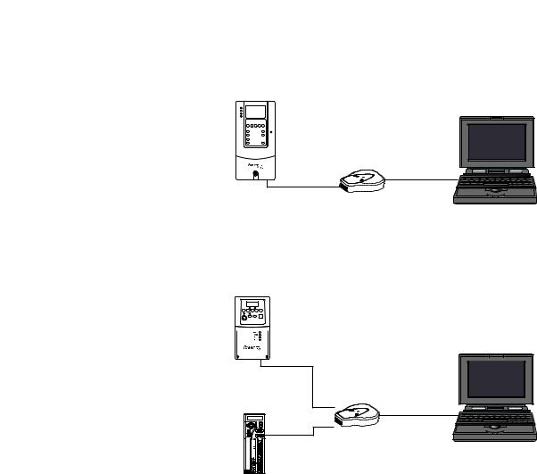
Figure 1.1 Connecting the Converter Between a DPI or SCANport Drive and
Computer
DPI or SCANport Drive
(PowerFlex 70 shown) Computer (Laptop or Desktop)
1203-USB
Converter
20-HIM-H10 |
USB Cable |
|
|
Cable |
|
Figure 1.2 Connecting the Converter Between a DSI Drive and Computer
DSI Drive (PowerFlex 40 shown)
22-HIM-H10
Cable
|
1203-USB |
Kinetix 3 Drive |
Converter |
|
or
USB Cable
 2090-CCMUSDS-48AA0x


 Cable (ordered separately)
Computer (Laptop or Desktop)
PowerFlex 1203-USB Converter User Manual
Publication DRIVES-UM001D-EN-P

1-8 Getting Started
Notes:
PowerFlex 1203-USB Converter User Manual
Publication DRIVES-UM001D-EN-P

Chapter 2
Installing the Converter
This chapter provides instructions for installing and removing the 1203-USB converter.
Topic |
Page |
|
|
Connecting the Cables |
2-1 |
|
|
Installing Connected Components Workbench Software |
2-12 |
|
|
Installing the USB Drivers |
2-4 |
|
|
Powering Up the Converter |
2-12 |
|
|
Removing the Converter |
2-13 |
|
|
Connecting the Cables |
Important: The converter must not be installed in an area where the |
|
ambient atmosphere contains volatile or corrosive gas, vapors |
|
or dust. If the converter is not going to be installed for a period |
|
of time, it must be stored in an area where it will not be exposed |
|
to a corrosive atmosphere. |
|
Only two of the three supplied cables are required to install the 1203-USB |
|
converter between the drive and computer. |
|
TIP: Always use the USB cable to connect the converter to the computer. |
|
For a list of compatible products, see Compatible Products on page 1-3. |
PowerFlex 1203-USB Converter User Manual
Publication DRIVES-UM001D-EN-P
2-2 Installing the Converter
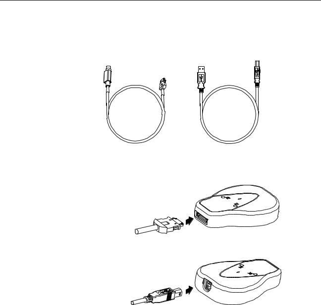
Connecting the Converter to a DPI or SCANport Drive and the Computer
Use the 20-HIM-H10 cable to connect the converter to a DPI or SCANport drive. Use the USB cable to connect the converter to the computer.
20-HIM-H10 Cable |
USB Cable |
1.Connect the 20-HIM-H10 cable between the converter and the DPI or SCANport drive.
20-HIM-H10 Cable
2. Connect the USB cable between the converter and the computer.
USB Cable
PowerFlex 1203-USB Converter User Manual
Publication DRIVES-UM001D-EN-P
Installing the Converter |
2-3 |
|
|
Connecting the Converter to a DSI Drive and the Computer
Use the 22-HIM-H10 cable to connect the converter to a DSI drive. Use the
USB cable to connect the converter to the computer.
2090-CCMUSDS-48AA0x Cable |
22-HIM-H10 Cable |
USB Cable |
(for Kinetix 3 drives and ordered separately) |
(for PowerFlex drives) |
|
Important: The 22-HIM-H10 cable shield must be properly grounded to provide EMC protection. For example, terminal 16 on a PowerFlex 4-Class drive and terminal C1 on a PowerFlex 520-Series drive should be connected to the drive earth ground. See the respective drive User Manual for additional information.
1.Connect the 22-HIM-H10 cable (required for PowerFlex drives) or the 2090-CCMUSDS-48AA0x cable (required for Kinetix 3 drives) between the converter and the DSI drive.
22-HIM-H10 Cable or
2090-CCMUSDS-48AA0x Cable
2. Connect the USB cable between the converter and the computer.
USB Cable
PowerFlex 1203-USB Converter User Manual
Publication DRIVES-UM001D-EN-P

2-4 |
Installing the Converter |
|
|
|
|
Installing the USB Drivers |
The following two USB drivers must be installed on your computer to |
|
|
|
enable the computer to recognize the 1203-USB converter when using any |
|
|
of the configuration tools (Connected Components Workbench, |
|
|
DriveExplorer, DriveExecutive, or HyperTerminal software): |
• USB Converter driver
• USB Serial Port driver
If you intend to use Connected Components Workbench software, version 2.xx or later, to configure the converter and connected drive, these two USB drivers are automatically installed during the installation of this software. However, if you intend to use an earlier version of this software tool or DriveExplorer, DriveExecutive, or HyperTerminal software, you must manually install these two USB drivers. This requires downloading and extracting both USB drivers to the computer, and then installing both USB drivers. For instructions to do this, see the next two subsections.
Download Both USB Drivers to the Computer
To obtain both USB drivers required for the 1203-USB converter and USB serial port, perform the following steps.
1. Go to the Allen-Bradley Web Updates website at http://www.ab.com/ support/abdrives/webupdate.
2. Click the 1203-USB link in the 7-Class or 4-Class Peripherals section.
3. Download the zip file to a unique location on your computer.
4. Unzip the file to access the executable files for both USB drivers.
Install Both USB Drivers
Most personal computers today use the Windows XP™ or Windows 7™ operating system. See the appropriate subsection below for instructions that correspond with the operating system being used.
When Using the Windows XP Operating System
1. After connecting the 1203-USB converter to a powered drive and to the computer, the ‘Found New Hardware Wizard’ screen should appear.
PowerFlex 1203-USB Converter User Manual
Publication DRIVES-UM001D-EN-P

Installing the Converter |
2-5 |
|
|
If this screen did not appear, perform the following steps:
a.Open the Windows Control Panel and double-click System.
b.In the System Properties window, click the Hardware tab.
c.Click Device Manager.
d.Expand ‘Universal Serial Bus controllers’ in the treeview.
e.Right-click the USB Converter and choose Update Driver.
f.When the above screen appears, proceed to step 2.
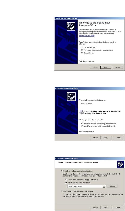
2.Click ‘No, not this time’.
3.Click Next > to continue (next wizard screen appears).
4. Click ‘Install from a list or specific location (Advanced)’.
PowerFlex 1203-USB Converter User Manual
Publication DRIVES-UM001D-EN-P
2-6 Installing the Converter
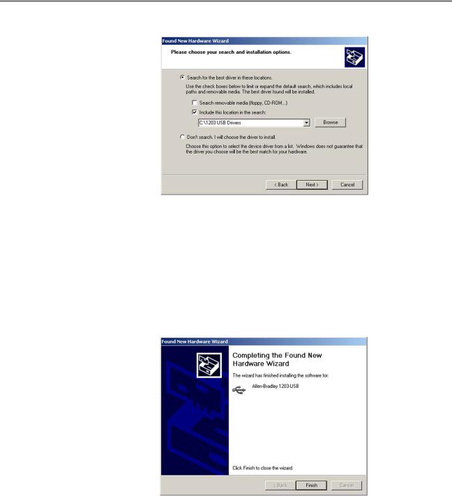
5. Click Next > to continue (next wizard screen appears).
6.Check ‘Include this location in the search’.
7.Click Browse.
Browse to the location on the computer where the executable files for both USB drivers were unzipped (step 4 in the Download Both USB Drivers to the Computer section).
8.Click Next >.
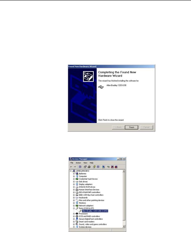
9.After the 1203-USB driver has been successfully installed, a confirmation screen appears.
10. Click Finish.
PowerFlex 1203-USB Converter User Manual
Publication DRIVES-UM001D-EN-P
Installing the Converter |
2-7 |
|
|
11.After approximately 20 seconds, the ‘Found New Hardware Wizard’ screen should appear again.
12.Click ‘No, not at this time’.
13.Click Next > to continue (next wizard screen appears).
14.Click ‘Install from a list or specific location (Advanced)’.
15.Click Next > to continue (next wizard screen appears).
PowerFlex 1203-USB Converter User Manual
Publication DRIVES-UM001D-EN-P
2-8 Installing the Converter
16.Check ‘Include this location in the search’.
17.Click Browse.
Browse to the location on the computer where the executable files for both USB drivers were unzipped (step 4 in the Download Both USB Drivers to the Computer section).
18.Click Next >.
19.After the USB Serial Port driver has been successfully installed, a confirmation screen appears.
20.Click Finish.
21.Verify that the drivers have been correctly installed by expanding Ports (COM & LPT) in the Device Manager treeview as shown below.
‘Allen-Bradley 1203-USB (COMx)’ should appear in the treeview. Note the COM port being used. This COM port number will be used later to configure a driver using RSLinx software to represent the connection on the COM port. This is required for either the Connected Components Workbench or DriveExecutive software tool. See Using Connected Components Workbench Software on page 3-2 or, for DriveExecutive software, Configuring the Converter on page D-2 for details.
PowerFlex 1203-USB Converter User Manual
Publication DRIVES-UM001D-EN-P

Installing the Converter |
2-9 |
|
|
When Using the Windows 7 Operating System
1.After connecting the 1203-USB converter to a powered drive and to the computer, open the Windows Control Panel.
2.Click Device Manager.
3.Expand ‘Other Devices’ in the treeview.
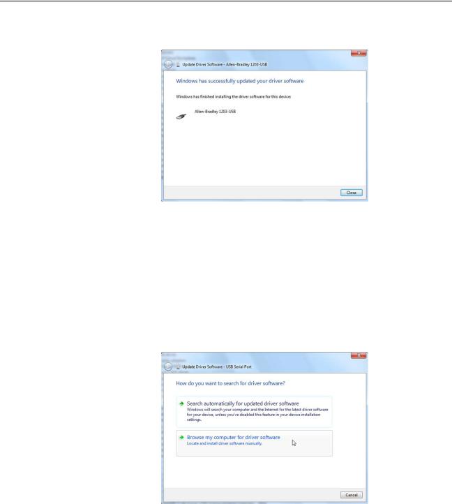
4.Right-click the USB Converter and choose ‘Update Driver Software’. The following screen appears.
5.Click ‘Browse my computer for driver software’. The following screen appears.
6.Check ‘Include subfolders’.
7.Click Browse.
Browse to the location on the computer where the executable files for both USB drivers were unzipped (step 4 in the Download Both USB Drivers to the Computer section).
8.Click Next.
PowerFlex 1203-USB Converter User Manual
Publication DRIVES-UM001D-EN-P
2-10 Installing the Converter
9.After the 1203-USB driver has been successfully installed, a confirmation screen appears.
10.Click Close.
11.After the USB Converter driver has been successfully installed, the USB Serial Port driver must be installed. Open the Windows Control Panel.
12.Click Device Manager.
13.Expand ‘Other Devices’ in the treeview.
14.Right-click the USB Serial Port and choose ‘Update Driver Software’. The following screen appears.
PowerFlex 1203-USB Converter User Manual
Publication DRIVES-UM001D-EN-P

Installing the Converter |
2-11 |
|
|
15.Click ‘Browse my computer for driver software’. The following screen appears.
16.Check ‘Include subfolders’.
17.Click Browse.
Browse to the location on the computer where the executable files for both USB drivers were unzipped (step 4 in the Download Both USB Drivers to the Computer section).
18.Click Next.
19.After the USB Serial Port driver has been successfully installed, a confirmation screen appears.
20. Click Close.
PowerFlex 1203-USB Converter User Manual
Publication DRIVES-UM001D-EN-P
2-12 Installing the Converter
Installing Connected
Components Workbench
Software
Powering Up the Converter
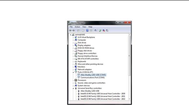
21.Verify that the drivers have been correctly installed by expanding Ports (COM & LPT) in the Device Manager treeview as shown below.
‘Allen-Bradley 1203-USB (COMx)’ should appear in the treeview. Note the COM port being used. This COM port number will be used later to configure a driver using RSLinx software to represent the connection on the COM port. This is required for either the Connected Components Workbench or DriveExecutive software tool. See Using Connected Components Workbench Software on page 3-2 or, for DriveExecutive software, Configuring the Converter on page D-2 for details.
If you do not have Connected Components Workbench software on your computer and intend to use it as your configuration tool, you can obtain a free copy. See User-Supplied Equipment on page 1-5 for details. Follow the instructions included with the software.
The 1203-USB converter receives power from the drive, so the drive must be powered before the converter will operate. The Diamond status indicator on the converter flashes green to indicate that the converter is properly installed and receiving power. If it is not green, see Chapter 4, Troubleshooting.
PowerFlex 1203-USB Converter User Manual
Publication DRIVES-UM001D-EN-P
Loading...