


 Loading...
Allen-Bradley
SLC to SCANport
Communications Module
(Cat. No 1203±SM1)
User
Manual

Important User
Information
Because of the variety of uses for the products described in this publication, those responsible for the application and use of this control equipment must satisfy themselves that all necessary steps have been taken to assure that each application and use meets all performance and safety requirements, including any applicable laws, regulations, codes and standards.
The illustrations shown in this guide are intended solely for purposes of example. Since there are many variables and requirements associated with any particular installation, Allen-Bradley does not assume responsibility or liability (to include intellectual property liability) for actual use based upon the examples shown in this publication.
Allen-Bradley publication SGI-1.1, Safety Guidelines for the Application, Installation, and Maintenance of Solid-State Control
(available from your local Allen-Bradley office), describes some important differences between solid-state equipment and electromechanical devices that should be taken into consideration when applying products such as those described in this publication.
Reproduction of the contents of this copyrighted publication, in whole or in part, without written permission of Allen-Bradley Company, Inc., is prohibited.
Throughout this manual we use notes to make you aware of safety considerations:
|
ATTENTION: Identifies information about practices |
|
! |
or circumstances that can lead to personal injury or |
|
death, property damage or economic loss. |
||
|
||
|
|
Attention statements help you to:
•identify a hazard
•avoid the hazard
•recognize the consequences
Important: Identifies information that is critical for successful application and understanding of the product.
SCANport is a registered trademark of Allen±Bradley Company, Inc.
SLC 500, SLC±5/02, and PLC±5/15 are registered trademarks of Allen±Bradley Company, Inc.

Table of Contents
Overview
Installing the SLC to SCANport Module
Using Basic Mode
Preface
Who Should Use this Manual? . . . . . . . . . . . . . . . . . . . . . . . . . . . |
P±1 |
Purpose of this Manual . . . . . . . . . . . . . . . . . . . . . . . . . . . . . . . . . |
P±1 |
Contents of this Manual . . . . . . . . . . . . . . . . . . . . . . . . . . . . . . |
P±2 |
Safety Precautions . . . . . . . . . . . . . . . . . . . . . . . . . . . . . . . . . . . . |
P±3 |
SLC Product Compatibility . . . . . . . . . . . . . . . . . . . . . . . . . . . . . . |
P±3 |
Terms and Abbreviations . . . . . . . . . . . . . . . . . . . . . . . . . . . . . . . |
P±3 |
Common Techniques Used in this Manual . . . . . . . . . . . . . . . . . . . |
P±4 |
Allen±Bradley Support . . . . . . . . . . . . . . . . . . . . . . . . . . . . . . . . . |
P±4 |
Local Product Support . . . . . . . . . . . . . . . . . . . . . . . . . . . . . . . |
P±4 |
Technical Product Assistance . . . . . . . . . . . . . . . . . . . . . . . . . . |
P±4 |
Chapter 1
Chapter Objectives . . . . . . . . . . . . . . . . . . . . . . . . . . . . . . . . . . . |
1±1 |
What is the SLC to SCANport Module? . . . . . . . . . . . . . . . . . . . . . |
1±1 |
What Functions Does the SLC to SCANport Module Provide? . . . . . |
1±2 |
Chapter 2
Chapter Objectives . . . . . . . . . . . . . . . . . . . . . . . . . . . . . . . . . . . |
2±1 |
Before You Install the Module . . . . . . . . . . . . . . . . . . . . . . . . . . . . |
2±1 |
Determine the Length of the SCANport Cable(s) . . . . . . . . . . . . . |
2±2 |
Determine the Placement of the SCANport Cables . . . . . . . . . . . |
2±2 |
Locate the DIP Switch . . . . . . . . . . . . . . . . . . . . . . . . . . . . . . . |
2±3 |
Installing the SLC to SCANport Module . . . . . . . . . . . . . . . . . . . . . |
2±4 |
Removing the SLC to SCANport Module . . . . . . . . . . . . . . . . . . . . |
2±6 |
Where Do I Go From Here? . . . . . . . . . . . . . . . . . . . . . . . . . . . . . |
2±6 |
Chapter 3
Chapter Objectives . . . . . . . . . . . . . . . . . . . . . . . . . . . . . . . . . . . |
3±1 |
What Does Basic Mode Provide? . . . . . . . . . . . . . . . . . . . . . . . . . |
3±1 |
Configuring the SLC to SCANport Module for Basic Mode . . . . . . . . |
3±1 |
Transferring Data . . . . . . . . . . . . . . . . . . . . . . . . . . . . . . . . . . . . . |
3±4 |
Channel Status Input Image Definitions . . . . . . . . . . . . . . . . . . . |
3±5 |
Channel Command Output Image Definitions . . . . . . . . . . . . . . . |
3±6 |
Example of Basic Mode Data Transfer . . . . . . . . . . . . . . . . . . . . . . |
3±6 |

ii
Using Enhanced Mode
Troubleshooting
Specifications
M0, M1, and G Files
Chapter 4
Chapter Objectives . . . . . . . . . . . . . . . . . . . . . . . . . . . . . . . . . . . |
4±1 |
What Does Enhanced Mode Provide? . . . . . . . . . . . . . . . . . . . . . . |
4±1 |
What Are Datalinks? . . . . . . . . . . . . . . . . . . . . . . . . . . . . . . . . |
4±2 |
What Is Safe State Configuration Data? . . . . . . . . . . . . . . . . . . . |
4±2 |
What Is Messaging? . . . . . . . . . . . . . . . . . . . . . . . . . . . . . . . . |
4±3 |
Configuring the SLC to SCANport Module for Enhanced Mode . . . . |
4±3 |
Using the I/O Image . . . . . . . . . . . . . . . . . . . . . . . . . . . . . . . . . . . |
4±7 |
Enhanced Mode Interface . . . . . . . . . . . . . . . . . . . . . . . . . . . . . |
4±7 |
Configuring G Files . . . . . . . . . . . . . . . . . . . . . . . . . . . . . . . . . . . |
4±10 |
Using M Files . . . . . . . . . . . . . . . . . . . . . . . . . . . . . . . . . . . . . . . |
4±11 |
Examples of Enhanced Mode Data Transfer . . . . . . . . . . . . . . . . . |
4±16 |
Datalinks . . . . . . . . . . . . . . . . . . . . . . . . . . . . . . . . . . . . . . . . . |
4±23 |
Chapter 5
Chapter Objectives . . . . . . . . . . . . . . . . . . . . . . . . . . . . . . . . . . . |
5±1 |
LED States . . . . . . . . . . . . . . . . . . . . . . . . . . . . . . . . . . . . . . . . . |
5±1 |
Chapter 6
Chapter Objectives . . . . . . . . . . . . . . . . . . . . . . . . . . . . . . . . . . . |
6±1 |
Product Specifications . . . . . . . . . . . . . . . . . . . . . . . . . . . . . . . . . |
6±1 |
European Union Directive Compliance . . . . . . . . . . . . . . . . . . . . . . |
6±2 |
EMC Directive . . . . . . . . . . . . . . . . . . . . . . . . . . . . . . . . . . . . . |
6±2 |
Low Voltage Directive . . . . . . . . . . . . . . . . . . . . . . . . . . . . . . . . |
6±2 |
Appendix A
Appendix Objectives . . . . . . . . . . . . . . . . . . . . . . . . . . . . . . . . . . |
A±1 |
M0±M1 Files . . . . . . . . . . . . . . . . . . . . . . . . . . . . . . . . . . . . . . . . |
A±1 |
Configuring M0±M1 Files Using APS Software . . . . . . . . . . . . . . |
A±1 |
Addressing M0±M1 Files . . . . . . . . . . . . . . . . . . . . . . . . . . . . . |
A±2 |
Restrictions on Using M0±M1 Data File Addresses . . . . . . . . . . . |
A±3 |
Monitoring Bit Addresses . . . . . . . . . . . . . . . . . . . . . . . . . . . . . |
A±3 |
M0/M1 Monitoring Option Disabled . . . . . . . . . . . . . . . . . . . . |
A±3 |
M0/M1 Monitoring Option Enabled . . . . . . . . . . . . . . . . . . . . . |
A±4 |
Transferring Data Between Processor Files and M0 and M1 Files |
A±4 |
Access Time . . . . . . . . . . . . . . . . . . . . . . . . . . . . . . . . . . . . . . |
A±5 |
SLC 5/02 Processor Example . . . . . . . . . . . . . . . . . . . . . . . . |
A±6 |
SLC 5/03 Processor Example . . . . . . . . . . . . . . . . . . . . . . . . |
A±7 |
Minimizing the Scan Time . . . . . . . . . . . . . . . . . . . . . . . . . . . . . |
A±7 |
Capturing M0±M1 File Data . . . . . . . . . . . . . . . . . . . . . . . . . . . |
A±8 |
G Files . . . . . . . . . . . . . . . . . . . . . . . . . . . . . . . . . . . . . . . . . . . . |
A±8 |
Configuring G Files Using APS Software . . . . . . . . . . . . . . . . . . |
A±9 |
Editing G File Data . . . . . . . . . . . . . . . . . . . . . . . . . . . . . . . . . . |
A±10 |
Publication 1203±5.9 ±± October 1996

iii
SCANport Messaging
Appendix B
Appendix Objectives . . . . . . . . . . . . . . . . . . . . . . . . . . . . . . . . . . |
B±1 |
Message and Reply Structures . . . . . . . . . . . . . . . . . . . . . . . . . . . |
B±1 |
Available SCANport Messages . . . . . . . . . . . . . . . . . . . . . . . . . . . |
B±4 |
SLC SCANport Messaging Ladder Program . . . . . . . . . . . . . . . . . . |
B±4 |
Example Messages and Replies . . . . . . . . . . . . . . . . . . . . . . . . . . |
B±6 |
Read Number of Parameters . . . . . . . . . . . . . . . . . . . . . . . . . . |
B±7 |
Read Parameter Value . . . . . . . . . . . . . . . . . . . . . . . . . . . . . . . |
B±8 |
Read Parameter Name Text . . . . . . . . . . . . . . . . . . . . . . . . . . . |
B±9 |
Write Value to Parameter . . . . . . . . . . . . . . . . . . . . . . . . . . . . . |
B±10 |
Read Full Parameter . . . . . . . . . . . . . . . . . . . . . . . . . . . . . . . . |
B±11 |
Scaling Formulas . . . . . . . . . . . . . . . . . . . . . . . . . . . . . . . . . |
B±13 |
Set Default Parameter Values . . . . . . . . . . . . . . . . . . . . . . . . . . |
B±15 |
Restore Parameter Values from Non±volatile Storage . . . . . . . . . |
B±16 |
Save Parameter Values to Non±volatile Storage . . . . . . . . . . . . . |
B±17 |
Read Enum String for Value in Parameter . . . . . . . . . . . . . . . . . |
B±18 |
Read Product Number . . . . . . . . . . . . . . . . . . . . . . . . . . . . . . . |
B±19 |
Read Product Text . . . . . . . . . . . . . . . . . . . . . . . . . . . . . . . . . . |
B±20 |
Read Product Series Number . . . . . . . . . . . . . . . . . . . . . . . . . . |
B±21 |
Read Product Software Version . . . . . . . . . . . . . . . . . . . . . . . . |
B±22 |
Scattered Read . . . . . . . . . . . . . . . . . . . . . . . . . . . . . . . . . . . . |
B±23 |
Scattered Write . . . . . . . . . . . . . . . . . . . . . . . . . . . . . . . . . . . . |
B±25 |
Read Parameter Link from Parameter Number . . . . . . . . . . . . . . |
B±27 |
Write Parameter Link from Parameter Number . . . . . . . . . . . . . . |
B±28 |
Error Codes . . . . . . . . . . . . . . . . . . . . . . . . . . . . . . . . . . . . . . . . |
B±29 |
Publication 1203±5.9 ±± October 1996

iv
Publication 1203±5.9 ±± October 1996

Preface
Preface
Who Should Use this Manual?
Purpose of this Manual
Read this preface to familiarize yourself with the rest of the manual. This preface covers the following topics:
•who should use this manual
•the purpose of this manual
•safety precautions
•firmware support
•product compatibility
•terms and abbreviations
•conventions used in this manual
•Allen±Bradley support
Use this manual if you design, install, program, or troubleshoot control systems that use the Allen±Bradley SLC to SCANport communications module. You must have previous experience with and a basic understanding of electrical terminology, configuration procedures, equipment, and safety precautions for machinery and control systems.
To efficiently use this communications module, you must be able to program and operate an Allen-Bradley SLC controller.
This manual provides the information you need to install and use the SLC to SCANport communications module. This manual describes the procedures for installing, configuring, and troubleshooting the SLC to SCANport communications module.
For information on specific product features, refer to the product manual.
Important: Read this manual in its entirety before installing, operating, servicing, or configuring the SLC to SCANport communications module.
Publication 1203±5.9 ±± October 1996
P±2 |
Preface |
Contents of this Manual
This manual contains the following information:
Chapter: |
Title: |
Contents: |
|
|
|
|
|
|
Preface |
Describes the purpose, background, and scope of this |
|
|
manual. |
||
|
|
||
|
|
|
|
1 |
Overview |
Provides an overview of the SLC to SCANport |
|
communications module. |
|||
|
|
||
|
|
|
|
|
Installing the SLC |
Provides the procedures you need to install your SLC to |
|
2 |
to SCANport |
SCANport communications module and attach it to the |
|
|
Module |
SCANport network. |
|
|
|
|
|
|
|
Provides information that you need to configure your |
|
3 |
Using Basic Mode |
SLC to SCANport communications module for SLC |
|
|
|
basic mode operation. |
|
|
|
|
|
|
Using Enhanced |
Provides information that you need to configure your |
|
4 |
SLC to SCANport communications module for SLC |
||
Mode |
|||
|
enhanced mode operation. |
||
|
|
||
|
|
|
|
5 |
Troubleshooting |
Provides information about the LED indications and |
|
fault descriptions. |
|||
|
|
||
|
|
|
|
6 |
Specifications |
Provides the environmental, electrical, and |
|
communications specifications. |
|||
|
|
||
|
|
|
|
A |
M0, M1, and G |
Provides generic information about using the M0, M1, |
|
Files |
and G files. |
||
|
|||
|
|
|
|
B |
SCANport Message |
Provides a listing of some of the most commonly used |
|
Index |
SCANport message structures. |
||
|
|||
|
|
|
Publication 1203±5.9 ±± October 1996

Preface P±3
Safety Precautions |
Please read the following safety precautions carefully. |
!
!
ATTENTION: Only personnel familiar with SCANport devices and the associated machinery should plan or implement the installation, start-up, configuration, and subsequent maintenance of this communications module. Failure to comply may result in personal injury and/or equipment damage.
ATTENTION: The SLC to SCANport module contains ESD (Electrostatic Discharge) sensitive parts and assemblies. Static control precautions are required when installing, testing, or servicing this assembly. Component damage may result if you do not follow ESD control procedures. If you are not familiar with static control procedures, refer to Allen-Bradley Publication 8000-4.5.2, Guarding against Electrostatic Damage, or any other applicable ESD protection handbook.
SLC Product Compatibility
Terms and Abbreviations
The SLC to SCANport module is designed to be used with any SLC processor or adapter capable of supporting SLC rack±based modules.
The following terms and abbreviations are specific to this product. For a complete listing of Allen±Bradley terminology, refer to the
Allen±Bradley Industrial Automation Glossary.
In this manual, we refer to the:
•1203 SLC to SCANport communications peripheral as the SLC to
SCANport module.
•Any of the connected SCANport products as the drive or SCANport device. The current list of SCANport devices include the following: 1305 MICRO, 1336 FORCE, 1336 IMPACT, 1336 PLUS, 1394 digital motion control system, SMC Dialog Plus, SMP±3 smart motor protector, and 1397 DC drive.
Publication 1203±5.9 ±± October 1996
P±4 |
Preface |
Common Techniques Used in this Manual
"
Allen±Bradley Support
This manual follows these conventions:
•Bulleted lists provide information, not procedural steps.
•Numbered lists provide sequential steps or hierarchical information.
•Italic type is used for emphasis and chapter names.
We also use this convention to call attention to helpful information.
Allen±Bradley offers support services worldwide, with over 75 Sales/Support Offices, 512 authorized Distributors and 260 authorized Systems Integrators located throughout the United States alone, plus Allen±Bradley representatives in every major country in the world.
Local Product Support
Contact your local Allen±Bradley representative for:
•sales and order support
•product technical training
•warranty support
•support service agreements
Technical Product Assistance
If you need to contact Allen±Bradley for technical assistance, please review the information in the Troubleshooting chapter first. If you are still having problems, then call your local Allen±Bradley representative.
Publication 1203±5.9 ±± October 1996
Chapter 1
Overview
Chapter Objectives
What is the SLC to SCANport Module?
Chapter 1 provides descriptions of the following:
•the SLC to SCANport module
•the available functions
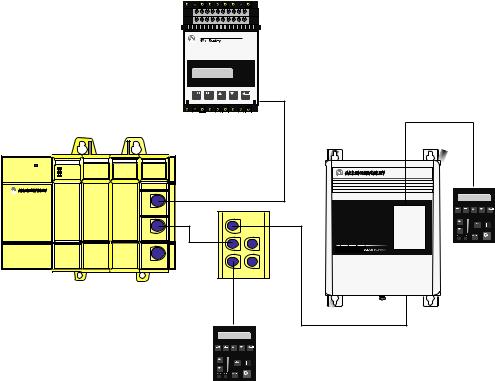
The SLC to SCANport module provides an interface between any SLC processor or other product that can control modules within a SLC rack and up to three SCANport devices as shown in Figure 1.1.
Figure 1.1
Example SLC to SCANport Module Set Up
SMC Dialog Plus
SLC Rack with SLC to SCANport Module
POWER |
SLC 5/01 CPU |
INPUT |
OUTPUT |
SCANport |
|
|
CHANNEL 1 |
||
|
PC RUN |
|
|
|
|
CPU Fault |
|
|
CHANNEL 2 |
|
FORCED I/O |
|
|
CHANNEL 3 |
|
BATTERY LOW |
|
|
0 |
8 |
0 |
8 |
1 |
9 |
1 |
9 |
2 |
10 |
2 |
10 |
3 |
11 |
3 |
11 |
4 |
12 |
|
Channel 1 |
4 |
12 |
||
5 |
13 |
5 |
13 |
6 |
14 |
6 |
14 |
7 |
15 |
7 |
15 |
|
|
|
Channel 2 |
Channel 3
1336 PLUS
1305
To connect more than three SCANport devices in a single rack, add additional SLC to SCANport modules to your SLC rack system.
You can use your SLC to SCANport module in a 4, 7, 10, or 13 slot SLC rack or a 2±slot expansion rack available for the fixed I/O configurations of SLC±500 processors.
Important: An SLC rack using this module needs an enclosure of at least 200 mm (8 in) in depth. You cannot place an SLC rack using the SLC to SCANport module in a 150 mm (6 in) deep enclosure.
Publication 1203±5.9 ±± October 1996

1±2 Overview
What Functions Does the SLC to SCANport Module Provide?
Your SLC processor or rack adapter determines what functions are available for the SLC to SCANport module.
If the device in the left hand slot |
Is basic mode |
Is enhanced mode |
|
of the SLC chassis is a: |
supported? |
supported? |
|
|
|
|
|
Fixed style controller (using an |
Yes |
No |
|
expansion rack) |
|||
|
|
||
|
|
|
|
SLC 5/01 controller |
Yes |
No |
|
|
|
|
|
SLC 5/02, 5/03, or 5/04 controller |
Yes |
Yes |
|
|
|
|
|
1747±OC open controller |
Yes |
Yes |
|
|
|
|
|
Any SLC rack adapter |
Yes |
No |
Future SLC product offerings may support enhanced mode communication.
The following table provides information about basic mode and enhanced mode.
Function |
Basic |
Enhanced |
|
Mode |
Mode |
||
|
|||
|
|
|
|
Maximum number of words of I/O per |
2 |
10 |
|
SCANport device |
|||
|
|
||
|
|
|
|
Total number of words of I/O for module |
8 |
32 |
|
|
|
|
|
16±bit Logic Command (to SCANport device) |
Yes |
Yes |
|
|
|
|
|
16±bit Logic Status (from SCANport device) |
Yes |
Yes |
|
|
|
|
|
16±bit Reference (to SCANport device) |
Yes |
Yes |
|
|
|
|
|
16±bit Feedback (from SCANport device) |
Yes |
Yes |
|
|
|
|
|
Datalinks |
No |
Yes |
|
|
|
|
|
Safe State Data |
No |
Yes |
|
|
|
|
|
Messaging |
No |
Yes |
Publication 1203±5.9 ±± October 1996

Chapter 2
Installing the SLC to SCANport Module
Chapter Objectives
Before You Install the
Module
Chapter 2 covers the following information:
•what you need to do before you install the SLC to SCANport module
•how to install the SLC to SCANport module
•how to remove the SLC to SCANport module
Important: You cannot place an SLC rack unit containing an SLC to SCANport module in an enclosure that is less than 200 mm (8 in) deep.
Before you install your SLC to SCANport module, you need to:
•Determine the length of your SCANport cable(s).
•Determine the placement of your SCANport cables.
•Locate the DIP switch on your SLC to SCANport module.
Publication 1203±5.9 ±± October 1996
2±2 |
Installing the SLC to SCANport Module |
Determine the Length of the SCANport Cable(s)
To connect your SLC to SCANport module to a SCANport device, you need to use an Allen±Bradley SCANport cable. The maximum cable length between any two peripheral devices connected to any SCANport device cannot exceed 10 meters (33 feet). Therefore, in Figure 2.1, A+B+C≤10 meters and D+B+C≤10 meters. However, you would not add the length of cable E to cables A, B, C, or D because it connects to a separate SCANport device (or channel).
Figure 2.1
Example of SCANport Cable Lengths
POWER |
SLC 5/01 CPU |
|
PC RUN |
|
CPU Fault |
|
FORCED I/O |
|
BATTERY LOW |
SCANport
CHANNEL 1  CHANNEL 2
  CHANNEL 3
Channel 1
Channel 2
Channel 3
E
C
A
D
B
Determine the Placement of the SCANport Cables
You must keep the SCANport cables away from high power cables. If your SCANport cables are placed too close to the power cables or run in parallel with power cables, you may introduce noise into the communications system, which can cause problems to your system. Make sure you physically mount and connect SCANport products following the installation guidelines available for each product.
Publication 1203±5.9 ±± October 1996

Installing the SLC to SCANport Module |
2±3 |
Figure 2.2
Examples of Cable Placements
POWER |
SLC 5/01 CPU |
SCANport |
|
|
CHANNEL 1 |
|
|
|
|
CHANNEL 2 |
|
|
|
CHANNEL 3 |
|
|
|
Channel 1 |
A |
|
|
Channel 2 |
|
|
|
Channel 3 |
|
B
SLC 5/01 CPU
POWER
A
B
SCANport
CHANNEL 1 
CHANNEL 2
CHANNEL 3 
Channel 1
Channel 2
Channel 3
A = Communications wire
B = Power wires
Locate the DIP Switch
You also need to locate a single configuration DIP switch on the module as shown in Figure 2.3.
Figure 2.3
Side View of the SLC to SCANport Module Showing DIP Switch Location
|
|
|
OPEN |
|
|
|
|
1 |
2 |
3 |
4 |
5 |
6 |
7 |
8 |
Publication 1203±5.9 ±± October 1996

2±4 |
Installing the SLC to SCANport Module |
Installing the SLC to SCANport Module
To install the SLC to SCANport module into the chassis:
1.Set the DIP switches. For each SCANport device connected to the SLC to SCANport module, you need to set two DIP switches to select what happens when the SLC processor or rack adapter faults or is placed in program for the appropriate channel.
|
|
Set this DIP switch: |
To these settings: |
|||||||
|
|
|
O |
|
|
|
|
|
|
|
|
|
|
± |
|
|
|
|
|
|
|
|
|
Channel 1 Fault/ |
1 |
2 |
3 |
4 |
5 |
6 |
7 |
8 |
|
|
|
|
|
|
|
|
|
|
|
|
|
Program State |
O |
|
|
|
|
|
|
|
|
|
(Switches 1 and 2) |
|
|
|
|
|
|
|
|
|
|
± |
|
|
|
|
|
|
|
|
|
|
|
|
|
|
|
|
|
|
|
|
2 |
|
1 |
2 |
3 |
4 |
5 |
6 |
7 |
8 |
|
1 |
|
||||||||
|
|
|
|
|
|
|
|
|
|
|
Switch 1 = Open (Off) |
|
|
|
|
|
|
|
|
|
|
Switch 2 = Closed (On) |
|
|
|
|
|
|
|
|
|
|
|
|
OPEN |
O |
|
|
|
|
|
|
|
O |
O |
|
± |
|
|
|
|
|
|
|
F |
N |
5 |
1 2 3 4 5 6 7 8 |
|||||||
F |
|
4 |
|
|
|
|
|
|
|
|
|
3 |
|
|
|
|
|
|
|
|
|
|
|
2 |
|
|
|
|
|
|
|
|
|
|
1 |
|
|
|
|
|
|
|
|
|
|
|
O |
|
|
|
|
|
|
|
|
|
|
± |
|
|
|
|
|
|
|
|
|
|
1 |
2 |
3 |
4 |
5 |
6 |
7 |
8 |
|
|
|
O |
|
|
|
|
|
|
|
|
|
|
± |
|
|
|
|
|
|
|
|
|
Channel 2 Fault/ |
1 |
2 |
3 |
4 |
5 |
6 |
7 |
8 |
|
|
|
|
|
|
|
|
|
|
|
|
|
Program State |
O |
|
|
|
|
|
|
|
|
|
(Switches 3 and 4) |
|
|
|
|
|
|
|
|
|
|
± |
|
|
|
|
|
|
|
|
|
|
|
|
|
|
|
|
|
|
|
|
|
|
1 |
2 |
3 |
4 |
5 |
6 |
7 |
8 |
|
|
OPEN |
O |
|
|
|
|
|
|
|
|
|
|
± |
|
|
|
|
|
|
|
|
|
5 |
1 |
2 |
3 |
4 |
5 |
6 |
7 |
8 |
|
|
4 |
|
|
|
|
|
|
|
|
|
|
3 |
|
|
|
|
|
|
|
|
|
|
2 |
|
|
|
|
|
|
|
|
|
|
1 |
|
|
|
|
|
|
|
|
|
|
|
O |
|
|
|
|
|
|
|
|
|
|
± |
|
|
|
|
|
|
|
|
|
|
1 |
2 |
3 |
4 |
5 |
6 |
7 |
8 |
|
|
|
O |
|
|
|
|
|
|
|
|
|
|
± |
|
|
|
|
|
|
|
|
|
Channel 3 Fault/ |
1 |
2 |
3 |
4 |
5 |
6 |
7 |
8 |
|
|
|
|
|
|
|
|
|
|
|
|
|
Program State |
O |
|
|
|
|
|
|
|
|
|
(Switches 5 and 6) |
|
|
|
|
|
|
|
|
|
|
± |
|
|
|
|
|
|
|
|
|
|
|
|
|
|
|
|
|
|
|
|
|
|
1 |
2 |
3 |
4 |
5 |
6 |
7 |
8 |
|
|
OPEN |
O |
|
|
|
|
|
|
|
|
|
|
± |
|
|
|
|
|
|
|
|
|
5 |
1 |
2 |
3 |
4 |
5 |
6 |
7 |
8 |
|
|
4 |
||||||||
|
|
|
|
|
|
|
|
|
|
|
|
|
3 |
|
|
|
|
|
|
|
|
|
|
2 |
|
|
|
|
|
|
|
|
|
|
1 |
|
|
|
|
|
|
|
|
|
|
|
O |
|
|
|
|
|
|
|
|
|
|
± |
|
|
|
|
|
|
|
|
|
|
1 |
2 |
3 |
4 |
5 |
6 |
7 |
8 |
Publication 1203±5.9 ±± October 1996 |
|
|
|
|
|
|
|
|
||
|
|
To: |
|
|
|
|
|
SW1 |
SW2 |
Fault SCANport device |
|
Open |
Open |
||
(default) |
|||
(Off) |
(Off) |
||
|
|||
|
|
|
|
SW1 |
SW2 |
|
|
Closed |
Open |
Zero data |
|
(On) |
(Off) |
|
|
|
|
|
|
SW1 |
SW2 |
|
|
Open |
Closed |
Hold last state |
|
(Off) |
(On) |
|
|
|
|
|
|
SW1 |
SW2 |
Safe state data (enhanced mode |
|
Closed |
Closed |
||
only), Fault (basic mode only) |
|||
(On) |
(On) |
||
|
|||
|
|
|
|
SW3 |
SW4 |
Fault SCANport device |
|
Open |
Open |
||
(default) |
|||
(Off) |
(Off) |
||
|
|||
|
|
|
|
SW3 |
SW4 |
|
|
Closed |
Open |
Zero data |
|
(On) |
(Off) |
|
|
|
|
|
|
SW3 |
SW4 |
|
|
Open |
Closed |
Hold last state |
|
(Off) |
(On) |
|
|
|
|
|
|
SW3 |
SW4 |
Safe state data (enhanced mode |
|
Closed |
Closed |
||
only), Fault (basic mode only) |
|||
(On) |
(On) |
||
|
|||
|
|
|
|
SW5 |
SW6 |
Fault SCANport device |
|
Open |
Open |
||
(default) |
|||
(Off) |
(Off) |
||
|
|||
|
|
|
|
SW5 |
SW6 |
|
|
Closed |
Open |
Zero data |
|
(On) |
(Off) |
|
|
|
|
|
|
SW5 |
SW6 |
|
|
Open |
Closed |
Hold last state |
|
(Off) |
(On) |
|
|
|
|
|
|
SW5 |
SW6 |
Safe state data (enhanced mode |
|
Closed |
Closed |
||
only), Fault (basic mode only) |
|||
(On) |
(On) |
||
|
Installing the SLC to SCANport Module |
2±5 |
Set this DIP switch:
Switches 7 and 8
OPEN
 8
8  7
7  6 5 4 3 2 1
To these settings: |
|
|
To: |
|||||||||
|
|
|
|
|
|
|
|
|
|
|
|
|
O |
|
|
|
|
|
|
|
|
|
SW7 |
SW8 |
Reserved |
|
|
|
|
|
|
|
|
|
Open |
Open |
||
± |
|
|
|
|
|
|
|
|
|
|||
|
1 |
2 |
3 |
4 |
5 |
6 |
7 |
8 |
|
(Off) |
(Off) |
|
|
|
|
|
|
|
|
|
|
|
|
||
|
|
|
|
|
|
|
|
|
|
|
|
|
"If you select a state other than Fault, the channel enable bits located in the first two words of output data will retain their last state values.
This ensures that the enabled SCANport connections remain active for those states. The I/O data transferred to the SCANport device will change as configured by the DIP switch.
2. Turn off the chassis power supply.
ATTENTION: Do not install the SLC to SCANport module with the chassis power supply on. Inserting or
! removing the module with the chassis power supply on may damage the module.
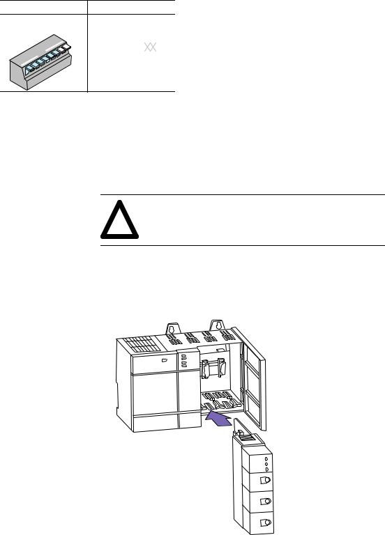
3. Select a slot for the module in the chassis. You may use any slot except the leftmost slot, which is reserved for the SLC 5/xx processor or rack adapter.
4. Insert the module into the slot you have selected.
CHANNEL |
1 |
CHANNEL |
2 |
|
|
CHANNEL |
3 |
Channel 1 |
|
Channel 2 |
|
Channel 3 |
|
Publication 1203±5.9 ±± October 1996
2±6 |
Installing the SLC to SCANport Module |
Removing the SLC to SCANport Module
Where Do I Go From Here?
5.Apply firm, even pressure to seat the module in the I/O chassis backplane connectors. Make sure the plastic tabs snap into the rack.
6.Connect the SCANport cable(s) from the SCANport device(s) to the SCANport connections in the front of the module.
Important: You must keep in mind that the maximum cable distance between any two devices connected to a single channel cannot exceed 10 meters (33 feet) of cable. Also, the SCANport cables must not be in close contact with the power cables.
You can insert or remove SCANport cables while a rack is powered. If a cable is removed while the channel is enabled, the connected SCANport device will fault unless otherwise configured at the SCANport device.
To remove the SLC to SCANport module from the chassis, you need to:
1.Remove the SCANport cables.
2.Make sure the rack power is removed.
3.Push in on the hooks on both ends of the module.
4.Gently pull the module from the chassis.
The SLC to SCANport module can operate in either basic mode or enhanced mode. Refer to Chapter 1 for a description of basic mode and enhanced mode.
If you plan to use: |
Go to: |
|
|
Basic mode |
Chapter 3 |
|
|
Enhanced mode |
Chapter 4 |
Publication 1203±5.9 ±± October 1996

Chapter 3
Chapter Objectives
What Does Basic Mode
Provide?
POWER |
SLC 5/01 CPU |
INPUT |
OUTPUT |
SCANport |
|
|
|
CHANNEL 1 |
|
|
|
|
|
CHANNEL 2 |
|
|
|
|
CHANNEL 3 |
|
|
|
|
Channel 1 |
|
|
|
|
Channel 2 |
|
|
|
|
Channel 3 |
Configuring the SLC to SCANport Module for Basic Mode
Using Basic Mode
Chapter 3 covers the following information:
•a description of what basic mode provides
•how to configure the SLC to SCANport module for basic mode
•how to transfer data
Basic mode sends a 16±bit logic command and a 16±bit analog reference from the module to each SCANport device. It receives a 16±bit logic status and a 16±bit analog feedback signal from each connected SCANport device.
16-bit logic command
16-bit analog reference
16-bit logic status
16-bit analog feedback
16-bit logic command
16-bit analog reference
16-bit logic status
16-bit analog feedback
16-bit logic command
16-bit analog reference (not used by SMC)
16-bit logic status
16-bit analog feedback
1305
1336
SMC
To configure the SLC to SCANport module for basic mode using the Advanced Programming Software (APS), you need to:
1.Create a file.
2.Enter a file name. For example purposes, we are using SM1_AP as the file name.
3.Highlight the processor as shown in Figure 3.1.
Publication 1203±5.9 ±± October 1996

3±2 |
Using Basic Mode |
Figure 3.1
Example APS Screen
Highlight the processor you want to use. For example, 1747±L532.
4.Press the F2 key.
5.Depending on your processor and version of APS, you may be asked to enter the operating system that your processor uses.
6.Press F5 to configure the I/O. The screen shown in Figure 3.2 is displayed.
Figure 3.2
Example I/O Configuration Screen
Publication 1203±5.9 ±± October 1996

Using Basic Mode |
3±3 |
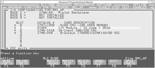
7.Move the cursor to the slot containing the SLC to SCANport module.
8.Press F5 to modify the slot. The screen shown in Figure 3.3 is displayed.
Figure 3.3
Prompt to Enter the Module ID Code
9.Enter the module ID code. For basic mode, the module ID code is 3516.
10.Press the Enter key.
When you have entered the module ID code, you are returned to the screen shown in Figure 3.2 with the selected module now shown. If you press F9, the screen shown in Figure 3.4 shows the configuration information for the SLC to SCANport module. You should not need to change this information for basic mode.
Figure 3.4
Specialty Module Configuration Screen
Figure 3.5 shows an example of a completed I/O configuration.
Publication 1203±5.9 ±± October 1996
3±4 |
Using Basic Mode |
Figure 3.5
An Example of a Completed I/O Configuration
Transferring Data
To transfer data using the SLC to SCANport module, you need to be familiar with how the SLC I/O image table represents the internal data I/O mapping and how the input and output image channel status bits are defined.
When the SLC to SCANport module is configured as a basic mode module, the internal data I/O mapping is represented within the SLC image table as the following:
Output Image |
|
Input Image |
||
Channel 2 Cmd |
Channel 1 Cmd |
Word 0 |
Channel 2 Stat |
Channel 1 Stat |
|
|
|
|
|
Reserved |
Channel 3 Cmd |
Word 1 |
Not Used |
Channel 3 Stat |
|
|
|
|
|
Logic Command Channel 1 |
Word 2 |
Logic Status Channel 1 |
||
|
|
|
|
|
Analog Reference Channel 1 |
Word 3 |
Analog Feedback Channel 1 |
||
|
|
|
|
|
Logic Command Channel 2 |
Word 4 |
Logic Status Channel 2 |
||
|
|
|
|
|
Analog Reference Channel 2 |
Word 5 |
Analog Feedback Channel 2 |
||
|
|
|
|
|
Logic Command Channel 3 |
Word 6 |
Logic Status Channel 3 |
||
|
|
|
|
|
Analog Reference Channel 3 |
Word 7 |
Analog Feedback Channel 3 |
||
|
|
|
|
|
Important: Different SCANport devices may define different meanings for the bits in the Logic Command and Logic Status fields. They may also use the Reference and Feedback differently. Refer to the manual for the specific SCANport device for more information.
Publication 1203±5.9 ±± October 1996

Using Basic Mode |
3±5 |
Channel Status Input Image Definitions
The Input Image Channel Status bits are defined as follows:
|
Channel 2 Status |
|
|
|
|
|
|
|
|
|
|
|
Channel 1 Status |
|||||||
|
|
|
|
|
|
|
|
|
|
|
|
|
|
|
|
|
|
|
|
|
Bit |
15 |
|
14 |
13 |
12 |
11 |
|
10 |
9 |
8 |
7 |
|
6 |
5 |
4 |
3 |
2 |
1 |
0 |
|
|
|
|
|
|
|
|
|
|
|
|
|
|
|
|
|
|
|
|
|
|
|
|
|
|
|
|
|
|
|
|
|
|
|
|
|
|
|
|
|
|
Word 0 |
|
|
|
Not Used |
|
V2 |
|
|
ID2 |
|
|
|
Not Used |
|
V1 |
|
ID1 |
|
|||
|
|
|
|
|
|
|
|
|
|
|
|
|
|
|
|
|
|
|
|
Word 1 |
|
|
|
|
|
|
|
|
Not Used |
|
|
|
|
|
|
V3 |
|
ID3 |
|
||
|
|
|
|
|
|
|
|
|
|
|
|
|
|
|
|
|
|
|
|
|
|
|
|
|
|
|
|
|
|
|
|
|
|
|
|
|
Channel 3 Status |
||||
|
|
These bits have the following definitions: |
|
|
|
|
|
|
||||||||||||
|
|
|
|
|
|
|
|
|
|
|
|
|
|
|
|
|
||||
|
|
|
This: |
|
|
|
|
|
|
|
Represents: |
|
|
|
|
|
||||
|
|
|
|
|
|
|||||||||||||||
|
|
|
|
|
SCANport Channel 1, 2, or 3 Connected Adapter Port ID |
|||||||||||||||
|
|
|
|
|
Number. This three bit field contains the adapter port number |
|||||||||||||||
|
|
|
ID1 |
|
read from the connector that channel 1, 2, or 3 is connected to on |
|||||||||||||||
|
|
|
ID2 |
|
the SCANport device. ID1, ID2, and ID3 should be between 1 |
|||||||||||||||
|
|
|
ID3 |
|
and 7. |
If ID1, ID 2, or ID3 is 7, the channel is not connected to |
||||||||||||||
|
|
|
|
|
a SCANport device, or the SCANport device may not be |
|||||||||||||||
|
|
|
|
|
powered. |
|
|
|
|
|
|
|
|
|
|
|
|
|||
SCANport Channel 1, 2, or 3 Valid Data bit. When high (1), the V1 Logic Status and Analog Feedback values are valid and can be V2 used. The V1, V2, and V3 bit will only go high after the
V3 program sets the corresponding data enable bit. When low (0), the values are not valid.
Publication 1203±5.9 ±± October 1996

3±6 |
Using Basic Mode |
Channel Command Output Image Definitions
The Output Image Channel Command bits are defined as follows:
|
Channel 2 Command |
|
|
|
|
|
|
|
|
|
|
|
|
Channel 1 Command |
|
||||||||||
|
|
|
|
|
|
|
|
|
|
|
|
|
|
|
|
|
|
|
|
|
|
|
|
|
|
Bit |
15 |
|
14 |
|
13 |
|
12 |
11 |
10 |
9 |
|
8 |
7 |
6 |
5 |
|
4 |
|
3 |
|
2 |
1 |
0 |
|
|
|
|
|
|
|
|
|
|
|
|
|
|
|
|
|
|
|
|
|
|
|
|
|
|
|
|
|
|
|
|
|
|
|
|
|
|
|
|
|
|
|
|
|
|
|
|
|
|
|
|
|
|
|
|
|
|
|
|
Not Used |
|
|
|
DE |
|
|
|
Not Used |
|
|
|
|
DE |
|
Word 0 |
||||
|
|
|
|
|
|
|
|
|
|
|
|
2 |
|
|
|
|
|
|
|
|
|
|
1 |
|
|
|
|
|
|
|
|
|
|
|
|
|
Not Used |
|
|
|
|
|
|
|
|
|
DE |
|
Word 1 |
||
|
|
|
|
|
|
|
|
|
|
|
|
|
|
|
|
|
|
|
|
|
|
|
3 |
|
|
|
|
|
|
|
|
|
|
|
|
|
|
|
|
|
|
|
|
|
|
Channel 3 Command |
|
||||
|
|
These bits have the following definitions: |
|
|
|
|
|
|
|
||||||||||||||||
|
|
|
|
|
|
|
|
||||||||||||||||||
|
|
|
|
|
|
|
SCANport Channel 1, 2, or 3 Data Enable bit. While low (0), |
||||||||||||||||||
|
|
|
|
|
|
|
the channel will not transfer I/O data between the module and |
||||||||||||||||||
|
|
|
DE1 |
|
|
the connected SCANport device. When high (1), the channel |
|||||||||||||||||||
|
|
|
DE2 |
|
|
becomes active to the SCANport device and transfers the |
|
||||||||||||||||||
|
|
|
DE3 |
|
|
appropriate I/O data. When reset to low (0), the channel |
|
||||||||||||||||||
|
|
|
|
|
|
|
disconnects from the SCANport device. This usually causes |
||||||||||||||||||
|
|
|
|
|
|
|
the connected SCANport device to fault. |
|
|
|
|
|
|
|
|||||||||||
Example of Basic Mode
Data Transfer
This section contains an example program that uses basic mode data transfer. The following portion of the program enables all three SCANport channels on the SLC to SCANport module.
Figure 3.6
Example of Enabling the SCANport Channels
| |
Channel 1 |
| |
| |
SCANport |
| |
| |
Enable |
| |
| |
O:1.0 |
| |
|±±±±±±±±±±±±±±±±±±±±±±±±±±±±±±±±±±±±±±±±±±±±±±±±±±È±±±±( )±±±±±±|
| |
| |
0 |
| | |
| |
|Channel 2 | | |
||
| |
|SCANport |
| | |
|
| |
|Enable |
| | |
|
| |
| |
O:1.0 |
| | |
| |
+±±±( )±±±±| | |
||
| |
| |
8 |
| | |
| |
|Channel 3 | | |
||
| |
|SCANport |
| | |
|
| |
|Enable |
| | |
|
| |
| |
O:1.1 |
| | |
| |
+±±±( )±±±±+ | |
||
| |
|
0 |
| |
Publication 1203±5.9 ±± October 1996
Using Basic Mode |
3±7 |
The portion of the program shown in Figure 3.7 provides start/stop control and a frequency reference to the 1305 drive connected to SCANport channel 1. The user start is a normally open push button, while the user stop is a normally closed push button.
Figure 3.7
Example of Drive 1 Control and Reference
| |
Drive 1 |
Drive 1 |
Drive 1 |
| |
| |
User |
User |
START |
| |
| |
Momentary |
Maintained |
Command |
| |
| |
START |
NOT STOP |
Bit |
| |
| |
Input |
Input |
|
| |
| |
I:2.0 |
I:2.0 |
O:1.2 |
| |
|±±±±±] [±±±±±±±±±±±±±±±±±±±] [±±±±±±±±±±±±±±±±±±±±±±±±±È±±±( )±±±±±|
| | |
0 |
|
| |
1 |
1 |
| |
| |Drive 1 |
|Drive 1 |
| |
|
|
| |
|
| |START |
|RUNNING |
| |
|
|
| |
|
| |Command |
|Status |
| |
|
|
| |
|
| |Bit |
|Bit |
| |
|
|
| |
|
| | |
O:1.2 |
I:1.2 |
| |
|
|
| |
| +±±±] [±±±±±±±±]/[±±±±+ |
|
|
| |
|||
| |
1 |
1 |
|
|
|
| |
| |
Drive 1 |
|
|
|
Drive 1 |
| |
| |
User |
|
|
|
STOP |
| |
| |
Maintained |
|
|
|
Command |
| |
| |
NOT STOP |
|
|
|
Bit |
| |
| |
Input |
|
|
|
|
| |
| |
I:2.0 |
|
|
|
O:1.2 |
| |
|±±±±±]/[±±±±±±±±±±±±±±±±±±±±±±±±±±±±±±±±±±±±±±±±±±±±±È±±±±±( )±±±±±|
| | |
1 |
|
| |
|
0 |
| |
| |Drive 1 |
|Drive 1 |
| |
|
|
| |
|
| |STOP |
|RUNNING |
| |
|
|
| |
|
| |Command |
|Status |
| |
|
|
| |
|
| |Bit |
|Bit |
| |
|
|
| |
|
| | |
O:1.2 |
I:1.2 |
| |
|
|
| |
| +±±±] [±±±±±±±±] [±±±±+ |
|
|
| |
|||
| |
0 |
1 |
|
|
|
| |
| |
|
|
|
Drive 1 |
|
| |
| |
|
|
|
Frequency |
|
| |
| |
|
|
|
Reference |
|
| |
| |
|
|
|
+MOV±±±±±±±±±±±±±±±+ | |
||
|±±±±±±±±±±±±±±±±±±±±±±±±±±±±±±±±±±±±±±±±±±±±±|MOVE |
|
+ȱ| |
||||
| |
|
|
|
|Source |
N20:0| | |
|
| |
|
|
|
| |
|
0| | |
| |
|
|
|
|Dest |
O:1.3| | |
|
| |
|
|
|
| |
|
0| | |
| |
|
|
|
+±±±±±±±±±±±±±±±±±±+ | |
||
Publication 1203±5.9 ±± October 1996

3±8 Using Basic Mode
The portion of the program shown in Figure 3.8 provides start/stop control and a frequency reference to the 1305 drive connected to SCANport channel 2. This section functions the same as that shown in Figure 3.7 except for the changes in addresses.
Figure 3.8
Example of Drive 2 Control and Reference
| |
Drive 2 |
Drive 2 |
Drive 2 |
| |
| |
User |
User |
START |
| |
| |
Momentary |
Maintained |
Command |
| |
| |
START |
NOT STOP |
Bit |
| |
| |
Input |
Input |
|
| |
| |
I:2.0 |
I:2.0 |
O:1.4 |
| |
|±±±±±] [±±±±±±±±±±±±±±±±±±±] [±±±±±±±±±±±±±±±±±±±±±±±±±È±±±( )±±±±±|
| | |
2 |
|
| |
3 |
1 |
| |
| |Drive 2 |
|Drive 2 |
| |
|
|
| |
|
| |START |
|RUNNING |
| |
|
|
| |
|
| |Command |
|Status |
| |
|
|
| |
|
| |Bit |
|Bit |
| |
|
|
| |
|
| | |
O:1.4 |
I:1.4 |
| |
|
|
| |
| +±±±] [±±±±±±±±]/[±±±±+ |
|
|
| |
|||
| |
1 |
1 |
|
|
|
| |
| |
Drive 2 |
|
|
|
Drive 2 |
| |
| |
User |
|
|
|
STOP |
| |
| |
Maintained |
|
|
|
Command |
| |
| |
NOT STOP |
|
|
|
Bit |
| |
| |
Input |
|
|
|
|
| |
| |
I:2.0 |
|
|
|
O:1.4 |
| |
|±±±±±]/[±±±±±±±±±±±±±±±±±±±±±±±±±±±±±±±±±±±±±±±±±±±±±È±±±±±( )±±±±±|
| | |
3 |
|
| |
|
0 |
| |
| |Drive 2 |
|Drive 2 |
| |
|
|
| |
|
| |STOP |
|RUNNING |
| |
|
|
| |
|
| |Command |
|Status |
| |
|
|
| |
|
| |Bit |
|Bit |
| |
|
|
| |
|
| | |
O:1.4 |
I:1.4 |
| |
|
|
| |
| +±±±] [±±±±±±±±] [±±±±+ |
|
|
| |
|||
| |
0 |
1 |
|
|
|
| |
| |
|
|
|
Drive 2 |
|
| |
| |
|
|
|
Frequency |
|
| |
| |
|
|
|
Reference |
|
| |
| |
|
|
|
+MOV±±±±±±±±±±±±±±±+ | |
||
|±±±±±±±±±±±±±±±±±±±±±±±±±±±±±±±±±±±±±±±±±±±±±|MOVE |
|
+ȱ| |
||||
| |
|
|
|
|Source |
N20:1| | |
|
| |
|
|
|
| |
|
0| | |
| |
|
|
|
|Dest |
O:1.5| | |
|
| |
|
|
|
| |
|
0| | |
| |
|
|
|
+±±±±±±±±±±±±±±±±±±+ | |
||
Publication 1203±5.9 ±± October 1996
Using Basic Mode |
3±9 |
The portion of the program shown in Figure 3.9 provides start/stop control and a frequency reference to the 1305 drive connected to SCANport channel 3. This section functions the same as that shown in Figure 3.7 and Figure 3.8 except for the changes in address.
Figure 3.9
Example of Drive 3 Control and Reference
| |
Drive 3 |
Drive 3 |
Drive 3 |
| |
| |
User |
User |
START |
| |
| |
Momentary |
Maintained |
Command |
| |
| |
START |
NOT STOP |
Bit |
| |
| |
Input |
Input |
|
| |
| |
I:2.0 |
I:2.0 |
O:1.6 |
| |
|±±±±±] [±±±±±±±±±±±±±±±±±±±] [±±±±±±±±±±±±±±±±±±±±±±±±±È±±±( )±±±±±|
| | |
4 |
|
| |
5 |
1 |
| |
| |Drive 3 |
|Drive 3 |
| |
|
|
| |
|
| |START |
|RUNNING |
| |
|
|
| |
|
| |Command |
|Status |
| |
|
|
| |
|
| |Bit |
|Bit |
| |
|
|
| |
|
| | |
O:1.6 |
I:1.6 |
| |
|
|
| |
| +±±±] [±±±±±±±±]/[±±±±+ |
|
|
| |
|||
| |
1 |
1 |
|
|
|
| |
| |
Drive 3 |
|
|
|
Drive 3 |
| |
| |
User |
|
|
|
STOP |
| |
| |
Maintained |
|
|
|
Command |
| |
| |
NOT STOP |
|
|
|
Bit |
| |
| |
Input |
|
|
|
|
| |
| |
I:2.0 |
|
|
|
O:1.6 |
| |
|±±±±±]/[±±±±±±±±±±±±±±±±±±±±±±±±±±±±±±±±±±±±±±±±±±±±±È±±±±±( )±±±±±|
| | |
5 |
|
| |
|
0 |
| |
| |Drive 3 |
|Drive 3 |
| |
|
|
| |
|
| |STOP |
|RUNNING |
| |
|
|
| |
|
| |Command |
|Status |
| |
|
|
| |
|
| |Bit |
|Bit |
| |
|
|
| |
|
| | |
O:1.6 |
I:1.6 |
| |
|
|
| |
| +±±±] [±±±±±±±±] [±±±±+ |
|
|
| |
|||
| |
0 |
1 |
|
|
|
| |
| |
|
|
|
Drive 3 |
|
| |
| |
|
|
|
Frequency |
|
| |
| |
|
|
|
Reference |
|
| |
| |
|
|
|
+MOV±±±±±±±±±±±±±±±+ | |
||
|±±±±±±±±±±±±±±±±±±±±±±±±±±±±±±±±±±±±±±±±±±±±±|MOVE |
|
+ȱ| |
||||
| |
|
|
|
|Source |
N20:2| | |
|
| |
|
|
|
| |
|
0| | |
| |
|
|
|
|Dest |
O:1.7| | |
|
| |
|
|
|
| |
|
0| | |
| |
|
|
|
+±±±±±±±±±±±±±±±±±±+ | |
||
Publication 1203±5.9 ±± October 1996
3±10 |
Using Basic Mode |
The following data table shows the input data read from the SLC to
SCANport module via the SLC backplane.
address |
15 |
data |
0 |
|
|
|
I:1 |
0000 |
0000 |
0000 |
0000 |
Drives 1 & 2 SCANport Channel Status |
|
I:1.1 |
0000 |
0000 |
0000 |
0000 |
Drive 3 SCANport Channel Status |
|
I:1.2 |
0000 |
0000 |
0000 |
0000 |
Drive 1 Logic Status |
|
I:1.3 |
0000 |
0000 |
0000 |
0000 |
Drive 1 Feedback |
|
I:1.4 |
0000 |
0000 |
0000 |
0000 |
Drive 2 |
Logic Status |
I:1.5 |
0000 |
0000 |
0000 |
0000 |
Drive 2 |
Feedback |
I:1.6 |
0000 |
0000 |
0000 |
0000 |
Drive 3 |
Logic Status |
I:1.7 |
0000 |
0000 |
0000 |
0000 |
Drive 3 |
Feedback |
The following data table shows the data to be sent to the SLC to
SCANport module via the SLC backplane.
address |
15 |
data |
0 |
|
|
|
O:1 |
0000 |
0000 |
0000 |
0000 |
Drives 1 & 2 SCANport Channel Enables |
|
O:1.1 |
0000 |
0000 |
0000 |
0000 |
Drive 3 SCANport Channel Enable |
|
O:1.2 |
0000 |
0000 |
0000 |
0000 |
Drive 1 Logic Command |
|
O:1.3 |
0000 |
0000 |
0000 |
0000 |
Drive 1 Reference |
|
O:1.4 |
0000 |
0000 |
0000 |
0000 |
Drive 2 |
Logic Command |
O:1.5 |
0000 |
0000 |
0000 |
0000 |
Drive 2 |
Reference |
O:1.6 |
0000 |
0000 |
0000 |
0000 |
Drive 1 |
Logic Command |
O:1.7 |
0000 |
0000 |
0000 |
0000 |
Drive 1 |
Reference |
Publication 1203±5.9 ±± October 1996

Chapter 4
Chapter Objectives
What Does Enhanced
Mode Provide?
POWER |
SLC 5/01 CPU |
INPUT |
OUTPUT |
SCANport |
|
|
|
CHANNEL 1 |
|
|
|
|
|
CHANNEL 2 |
|
|
|
|
CHANNEL 3 |
|
|
|
|
Channel 1 |
|
|
|
|
Channel 2 |
|
|
|
|
Channel 3 |
Using Enhanced Mode
Chapter 4 covers the following information:
•a description of what enhanced mode provides
•how to configure the SLC to SCANport module for enhanced mode
•how to use the I/O image
•how to configure G files
•how to use M files
Enhanced mode supports the basic mode features which include a 16±bit logic command and a 16±bit analog reference from the module to each SCANport device as well as a 16±bit logic status and a 16±bit analog feedback signal back from each connected SCANport device.
In addition, enhanced mode optionally provides datalinks, safe state data, and messaging.
8 words in/8 words out Messages
16-bit logic command
16-bit analog reference
16-bit logic status
16-bit analog feedback
8 words in/8 words out Messages
16-bit logic command
16-bit analog reference
16-bit logic status
16-bit analog feedback
8 words in/8 words out (not used by SMC)
 Messages 16-bit logic command
16-bit analog reference (not used by SMC)
16-bit logic status
16-bit analog feedback
1305
1336
SMC
Publication 1203±5.9 ±± October 1996

4±2 |
Using Enhanced Mode |
What Are Datalinks?
Datalinks let you cyclically transfer parameter values to and from a SCANport device (provided that the SCANport device supports datalinks). By using datalinks, you can change the value of a parameter without using the SLC to SCANport messaging function. Each datalink consists of two 16±bit words of input and two 16±bit words of output when enabled. Up to 8 words in and 8 words out of data are available if supported in the connected SCANport device.
SCANport devices that support this function have a group of parameters for datalink configuration. These parameters are identified as Data In A1±D2 and Data Out A1±D2. To use datalinks, you need to:
1.Set up a configuration file, called a G file, to enable the datalinks from the SLC to SCANport module side.
2.Configure or link the Data In A1±D2 and Data Out A1±D2 parameters in the SCANport device.
Setting up the G file is covered in more detail later in this chapter.
What Is Safe State Configuration Data?
You can select constant values that your SLC to SCANport module will maintain in the event of an SLC processor mode change or error. These constant values are referred to as safe state data. When the SLC is placed in program mode or an SLC fault occurs, the control outputs can be set to automatically switch to the constant values set in the safe state data words. This lets you define a safe operating state for controlled devices that depend on a pre±programmed output from the module.
ATTENTION: Use the G file to configure your safe state values based on your knowledge of how the
! SCANport devices connected on each channel operate. Refer to the manual for your SCANport device for additional information.
Refer to Chapter 2 for the DIP switch configuration for fault/program state.
Publication 1203±5.9 ±± October 1996
Loading...