


 Loading...
User Manual
Redundant I/O System
Catalog Numbers 1715-AENTR, 1715-IB16D, 1715-OB8DE, 1715-IF16, 1715-OF8I

Important User Information
Read this document and the documents listed in the additional resources section about installation, configuration, and operation of this equipment before you install, configure, operate, or maintain this product. Users are required to familiarize themselves with installation and wiring instructions in addition to requirements of all applicable codes, laws, and standards.
Activities including installation, adjustments, putting into service, use, assembly, disassembly, and maintenance are required to be carried out by suitably trained personnel in accordance with applicable code of practice.
If this equipment is used in a manner not specified by the manufacturer, the protection provided by the equipment may be impaired.
In no event will Rockwell Automation, Inc. be responsible or liable for indirect or consequential damages resulting from the use or application of this equipment.
The examples and diagrams in this manual are included solely for illustrative purposes. Because of the many variables and requirements associated with any particular installation, Rockwell Automation, Inc. cannot assume responsibility or liability for actual use based on the examples and diagrams.
No patent liability is assumed by Rockwell Automation, Inc. with respect to use of information, circuits, equipment, or software described in this manual.
Reproduction of the contents of this manual, in whole or in part, without written permission of Rockwell Automation, Inc., is prohibited.
Throughout this manual, when necessary, we use notes to make you aware of safety considerations.
WARNING: Identifies information about practices or circumstances that can cause an explosion in a hazardous environment, which may lead to personal injury or death, property damage, or economic loss.
ATTENTION: Identifies information about practices or circumstances that can lead to personal injury or death, property damage, or economic loss. Attentions help you identify a hazard, avoid a hazard, and recognize the consequence.
IMPORTANT Identifies information that is critical for successful application and understanding of the product.
Labels may also be on or inside the equipment to provide specific precautions.
SHOCK HAZARD: Labels may be on or inside the equipment, for example, a drive or motor, to alert people that dangerous voltage may be present.
BURN HAZARD: Labels may be on or inside the equipment, for example, a drive or motor, to alert people that surfaces may reach dangerous temperatures.
ARC FLASH HAZARD: Labels may be on or inside the equipment, for example, a motor control center, to alert people to potential Arc Flash. Arc Flash will cause severe injury or death. Wear proper Personal Protective Equipment (PPE). Follow ALL Regulatory requirements for safe work practices and for Personal Protective Equipment (PPE).
Allen-Bradley, Rockwell Software, Rockwell Automation, ControlFLASH, ControlLogix, Logix5000, Studio 5000 Logix Designer, RSLinx, RSLogix, Stratix 8000, and Studio 5000 are trademarks of Rockwell Automation, Inc.
Trademarks not belonging to Rockwell Automation are property of their respective companies.

Summary of Changes
New and Updated
Information
This publication contains new and updated information. Changes throughout this revision are marked by change bars, as shown to the right of this paragraph.
This table contains the changes made to this publication revision.
Table 1 - New and Updated Information
Topic |
Page |
|
|
Updates to include SIL 2 operations with L7 ControlLogix® controllers |
13 |
|
|
Studio 5000® Logix Designer™ application added throughout document and new |
14 |
information about who can use this system |
|
|
|
Using ControlLogix in SIL 2 Applications Safety Reference Manual added to Additional |
14 |
Resources section |
|
|
|
Added redundant 1715 adapter module and status indicator information |
15 |
|
|
Added information about using a 1715 system in a SIL 2 application |
16 |
|
|
Corrected drawing; added 1756-L7 controller and 1756-RM2 module; added reference |
20 |
for DLR topologies. |
|
|
|
Corrected drawing; added 1756-L7 controller and 1756-RM2 module |
21 |
|
|
Network status indicator information |
27 |
|
|
CIP messages |
30 |
|
|
Required connections for duplex and simplex operation |
31 |
|
|
Listen Only connections |
32 |
|
|
Conformal coating is available on all 1715 modules |
39 |
|
|
1715-A2A adapter base unit fuse graphic and removal and replacement information |
42 |
|
|
Digital input termination assembly removal and replacement of fuses |
47 |
|
|
Digital output termination assembly removal and replacement of fuses |
48 |
|
|
Analog input termination assembly removal and replacement of fuses |
49 |
|
|
Power requirements |
53 |
|
|
1715 chassis firmware upgrade; power recycle needed |
54 |
|
|
ControlFLASH™ revision number |
54 |
|
|
Power requirements for PELV/SELV |
63 |
|
|
Correction to system power graphic |
76 |
|
|
Digital Input diagram correction-standard inputs |
80 |
|
|
Short circuit information |
79 |
|
|
Digital Input diagram correction-line monitored inputs. Added reference for calibration |
81 |
drift checks. |
|
|
|
Corrected digital input termination assembly graphics |
85 |
|
|
Added Attention table for inductive loads |
87 |
|
|
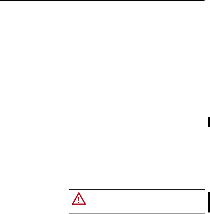
Added missing arrow on 1715-OB8DE function block diagram, going from the Control B |
88 |
box to the Output Control. |
|
|
|
Diagram correction-digital outputs |
93 |
|
|
Damaging pins when inserting/removing I/O modules under power can fault the system |
95 |
|
|
Corrected analog inputs graphic by removing footnote numbers on voltage |
96 |
|
|
Rockwell Automation Publication 1715-UM001C-EN-P - March 2014 |
3 |

Summary of Changes
Table 1 - New and Updated Information
Topic |
Page |
|
|
Added information about analog field loops, input modules and analog input field |
98 |
devices |
|
|
|
Find and record MAC addresses |
109 |
|
|
Added status indicator labels to the adapter graphic of the locking mechanism |
110 |
|
|
Changes throughout the Assign an IP Address on the BOOTP/DHCP Server section |
111 |
|
|
Verify BOOTP network settings Important table added |
112 |
|
|
Added last step to disable BootP/DHCP |
114 |
|
|
Module inhibiting when using multiple controllers |
128 |
|
|
Corrected ohms symbol and added DC on voltage numbers |
132 |
|
|
Shutdown states |
137 |
|
|
Removed references to the 1756-IA16 module |
138 |
|
|
Digital input module tags |
138 |
|
|
Digital output module tags |
139 |
|
|
Correction of table header to ControlLogix Analog I/O Modules and Components |
142 |
|
|
Added performance criteria for the analog input module |
143 |
|
|
Added performance criteria for the analog output module |
144 |
|
|
Module inhibiting when using multiple controllers |
145 |
|
|
Changed Get Support Now website to the Product and Compatibility Download Center |
150 |
website, added Add-On Profile versions for the adapter and I/O modules. Added |
|
reference to the release list of approved versions on www.tuvasi.com. |
|
|
|
Updated screen shots throughout to reflect Logix Designer version 21 interface and to |
160 |
include SIL 2 operation options |
|
|
|
Connections for Listen Only |
162 |
|
|
Module definition parameters for 1715-IB16D digital input module in Duplex mode for |
175 |
SIL 2 applications |
|
|
|
Connections for Listen Only |
188 |
|
|
Added Important table about changing Alarms/Limits values |
196 |
|
|
Added a new chapter about SIL 2 safety operation with 1715 redundant I/O |
201 |
|
|
Added a new chapter about SIL 2 Add-On Instructions with 1715 redundant I/O |
223 |
|
|
Corrected text from 3.9 to 4.3. |
282 |
|
|
Corrected text from 15 to 15.4. Added Calibration Drift Checks section. |
283 |
|
|
SIL 2 safety application online configuration restrictions |
285 |
|
|
Added appendix for PFD and PFH calculations for a SIL 2 system |
289 |
|
|
Added appendix for SIL 2 Applications Checklist |
303 |
|
|
Added appendix for Tag Definitions |
305 |
|
|
4 |
Rockwell Automation Publication 1715-UM001C-EN-P - March 2014 |

|
Table of Contents |
|
Preface |
Before You Begin . . . . . . . . . . . . . . . . . . . . . . . . . . . . . . . . . . . . . . . . . . . . . . . . |
13 |
|
Required Software. . . . . . . . . . . . . . . . . . . . . . . . . . . . . . . . . . . . . . . . . . . . |
13 |
|
Studio 5000 Environment . . . . . . . . . . . . . . . . . . . . . . . . . . . . . . . . . . . . . . . . |
14 |
|
Additional Resources . . . . . . . . . . . . . . . . . . . . . . . . . . . . . . . . . . . . . . . . . . . . . |
14 |
|
Chapter 1 |
|
Redundancy System Overview |
Redundant 1715 Adapter Modules . . . . . . . . . . . . . . . . . . . . . . . . . . . . |
15 |
|
1715 I/O Modules . . . . . . . . . . . . . . . . . . . . . . . . . . . . . . . . . . . . . . . . . . . |
16 |
|
1715 I/O Modules in SIL 2 Applications . . . . . . . . . . . . . . . . . . . . . . . |
16 |
|
System Architecture . . . . . . . . . . . . . . . . . . . . . . . . . . . . . . . . . . . . . . . . . . . . . . |
16 |
|
Termination Assemblies . . . . . . . . . . . . . . . . . . . . . . . . . . . . . . . . . . . . . . |
16 |
|
Base Unit Structure. . . . . . . . . . . . . . . . . . . . . . . . . . . . . . . . . . . . . . . . . . . |
17 |
|
1715-AENTR Adapter Modules. . . . . . . . . . . . . . . . . . . . . . . . . . . . . . . |
17 |
|
I/O Modules. . . . . . . . . . . . . . . . . . . . . . . . . . . . . . . . . . . . . . . . . . . . . . . . . |
17 |
|
Module Positioning in the 1715 Redundant I/O System. . . . . . . . . |
18 |
|
Layout the Hardware. . . . . . . . . . . . . . . . . . . . . . . . . . . . . . . . . . . . . . . . . . . . . |
20 |
|
System Context . . . . . . . . . . . . . . . . . . . . . . . . . . . . . . . . . . . . . . . . . . . . . . |
20 |
|
Simplex Architecture . . . . . . . . . . . . . . . . . . . . . . . . . . . . . . . . . . . . . . . . . |
22 |
|
Duplex Architecture. . . . . . . . . . . . . . . . . . . . . . . . . . . . . . . . . . . . . . . . . . |
23 |
|
Mixed Architecture. . . . . . . . . . . . . . . . . . . . . . . . . . . . . . . . . . . . . . . . . . . |
25 |
|
Bus Diagram . . . . . . . . . . . . . . . . . . . . . . . . . . . . . . . . . . . . . . . . . . . . . . . . . |
26 |
|
Switchover Considerations. . . . . . . . . . . . . . . . . . . . . . . . . . . . . . . . . . . . . . . . |
27 |
|
Obtaining a New IP Address . . . . . . . . . . . . . . . . . . . . . . . . . . . . . . . . . . |
28 |
|
Ethernet Topology . . . . . . . . . . . . . . . . . . . . . . . . . . . . . . . . . . . . . . . . . . . |
29 |
|
Communication on the EtherNet/IP Network . . . . . . . . . . . . . . . . . |
30 |
|
System Performance. . . . . . . . . . . . . . . . . . . . . . . . . . . . . . . . . . . . . . . . . . . . . . |
31 |
|
Connections . . . . . . . . . . . . . . . . . . . . . . . . . . . . . . . . . . . . . . . . . . . . . . . . . |
31 |
|
RPI . . . . . . . . . . . . . . . . . . . . . . . . . . . . . . . . . . . . . . . . . . . . . . . . . . . . . . . . . |
32 |
|
Connection and Data Format . . . . . . . . . . . . . . . . . . . . . . . . . . . . . . . . . |
32 |
|
Chapter 2 |
|
Installation Instructions |
Environment and Enclosure. . . . . . . . . . . . . . . . . . . . . . . . . . . . . . . . . . . |
34 |
|
Prevent Electrostatic Discharge . . . . . . . . . . . . . . . . . . . . . . . . . . . . . . . . |
34 |
|
European Hazardous Location Approval . . . . . . . . . . . . . . . . . . . . . . . |
35 |
|
Multi-point Network Communication Connections . . . . . . . . . . . . |
35 |
|
Field-side Power. . . . . . . . . . . . . . . . . . . . . . . . . . . . . . . . . . . . . . . . . . . . . . |
35 |
|
Removal and Insertion Under Power (RIUP) Fuses . . . . . . . . . . . . . |
35 |
|
North American Hazardous Location Approval . . . . . . . . . . . . . . . . |
36 |
|
Before You Begin . . . . . . . . . . . . . . . . . . . . . . . . . . . . . . . . . . . . . . . . . . . . . . . . |
37 |
|
Parts List . . . . . . . . . . . . . . . . . . . . . . . . . . . . . . . . . . . . . . . . . . . . . . . . . . . . |
37 |
|
Required Tools. . . . . . . . . . . . . . . . . . . . . . . . . . . . . . . . . . . . . . . . . . . . . . . |
38 |
|
Spacing Requirements . . . . . . . . . . . . . . . . . . . . . . . . . . . . . . . . . . . . . . . . |
38 |
|
System Hardware Components . . . . . . . . . . . . . . . . . . . . . . . . . . . . . . . . . . . |
39 |
|
1715-AENTR Adapter Redundant Module Pair . . . . . . . . . . . . . . . . |
40 |
|
1715 Digital and Analog I/O Modules . . . . . . . . . . . . . . . . . . . . . . . . . |
41 |
Rockwell Automation Publication 1715-UM001C-EN-P - March 2014 |
5 |

Table of Contents
1715-A2A Adapter Base Unit . . . . . . . . . . . . . . . . . . . . . . . . . . . . . . . . . 42 1715-A3IO I/O Base Unit . . . . . . . . . . . . . . . . . . . . . . . . . . . . . . . . . . . . 45 I/O Termination Assemblies . . . . . . . . . . . . . . . . . . . . . . . . . . . . . . . . . . 46 1715-C2 Expansion Cable. . . . . . . . . . . . . . . . . . . . . . . . . . . . . . . . . . . . . 52 1715-N2T and 1715-N2S Slot Filler Covers . . . . . . . . . . . . . . . . . . . . 52 Power Requirements . . . . . . . . . . . . . . . . . . . . . . . . . . . . . . . . . . . . . . . . . . 53 Cooling Requirements . . . . . . . . . . . . . . . . . . . . . . . . . . . . . . . . . . . . . . . . 53 Heating Requirements . . . . . . . . . . . . . . . . . . . . . . . . . . . . . . . . . . . . . . . . 53 Specify an Enclosure . . . . . . . . . . . . . . . . . . . . . . . . . . . . . . . . . . . . . . . . . . 54
System Software. . . . . . . . . . . . . . . . . . . . . . . . . . . . . . . . . . . . . . . . . . . . . . . . . . 54 Module Placement . . . . . . . . . . . . . . . . . . . . . . . . . . . . . . . . . . . . . . . . . . . . . . . 55 Base Units . . . . . . . . . . . . . . . . . . . . . . . . . . . . . . . . . . . . . . . . . . . . . . . . . . . 56 Install Summary. . . . . . . . . . . . . . . . . . . . . . . . . . . . . . . . . . . . . . . . . . . . . . . . . . 58 Step 1: Enclosure DIN Rail Assembly . . . . . . . . . . . . . . . . . . . . . . . . . . 58 Step 2: Build the System. . . . . . . . . . . . . . . . . . . . . . . . . . . . . . . . . . . . . . . 58 Product Dimensions. . . . . . . . . . . . . . . . . . . . . . . . . . . . . . . . . . . . . . . . . . . . . . 59 DIN Rail Mounting Dimensions. . . . . . . . . . . . . . . . . . . . . . . . . . . . . . . 59 DIN Rail Assembly . . . . . . . . . . . . . . . . . . . . . . . . . . . . . . . . . . . . . . . . . . . . . . . 60 Component Size and Weights . . . . . . . . . . . . . . . . . . . . . . . . . . . . . . . . . 60 Install the Power Supply . . . . . . . . . . . . . . . . . . . . . . . . . . . . . . . . . . . . . . . . . . 63 Install the Adapter Base Unit. . . . . . . . . . . . . . . . . . . . . . . . . . . . . . . . . . . . . . 64 Install the I/O Base Unit. . . . . . . . . . . . . . . . . . . . . . . . . . . . . . . . . . . . . . . . . . 64 Install Termination Assembly to I/O Base Unit. . . . . . . . . . . . . . . . . . . . . 67 Mount Termination Assemblies . . . . . . . . . . . . . . . . . . . . . . . . . . . . . . . 68 Mount I/O Expansion Cable . . . . . . . . . . . . . . . . . . . . . . . . . . . . . . . . . . . . . . 70 Cable Assembly. . . . . . . . . . . . . . . . . . . . . . . . . . . . . . . . . . . . . . . . . . . . . . . 70 Expansion Cable. . . . . . . . . . . . . . . . . . . . . . . . . . . . . . . . . . . . . . . . . . . . . . 71 Install Expansion Cable . . . . . . . . . . . . . . . . . . . . . . . . . . . . . . . . . . . . . . . 72 Wire the Adapter. . . . . . . . . . . . . . . . . . . . . . . . . . . . . . . . . . . . . . . . . . . . . . . . . 76 Connect the 24V DC System Power . . . . . . . . . . . . . . . . . . . . . . . . . . . 76 Wire the Ground Connection . . . . . . . . . . . . . . . . . . . . . . . . . . . . . . . . . 78 Connect Field Wiring . . . . . . . . . . . . . . . . . . . . . . . . . . . . . . . . . . . . . . . . . . . . 79 Recommended Circuits for Digital Inputs . . . . . . . . . . . . . . . . . . . . . . 80 Recommended Circuits for Digital Outputs . . . . . . . . . . . . . . . . . . . . 87 1715-OB8DE Digital Output Module Functional Block Diagram 88 Recommended Circuits for Analog Inputs . . . . . . . . . . . . . . . . . . . . . . 94 Recommended Wiring for Analog Output Modules . . . . . . . . . . . . 100 Connect the Adapter to the Ethernet Network . . . . . . . . . . . . . . . . . . . . 102 Module Keying. . . . . . . . . . . . . . . . . . . . . . . . . . . . . . . . . . . . . . . . . . . . . . . . . . 103 Verify Coding Pegs . . . . . . . . . . . . . . . . . . . . . . . . . . . . . . . . . . . . . . . . . . 105 Install the Adapter Modules . . . . . . . . . . . . . . . . . . . . . . . . . . . . . . . . . . . . . . 107 Assign an IP Address. . . . . . . . . . . . . . . . . . . . . . . . . . . . . . . . . . . . . . . . . . . . . 111 Step 1: Assign an IP Address on the BOOTP/DHCP Server . . . . 111 Step 2: Configure the Module with RSLinx Software . . . . . . . . . . . 114 Install the I/O Modules. . . . . . . . . . . . . . . . . . . . . . . . . . . . . . . . . . . . . . . . . . 117 Install Slot Filler Covers . . . . . . . . . . . . . . . . . . . . . . . . . . . . . . . . . . . . . . . . . 120 Remove Modules . . . . . . . . . . . . . . . . . . . . . . . . . . . . . . . . . . . . . . . . . . . . . . . . 121
6 |
Rockwell Automation Publication 1715-UM001C-EN-P - March 2014 |

Table of Contents
Digital I/O Operation
Using 1715 Analog I/O
Module Features
Chapter 3
1715 Digital Module Overview. . . . . . . . . . . . . . . . . . . . . . . . . . . . . . . . . . . 123 1715-IB16D Digital Input Module . . . . . . . . . . . . . . . . . . . . . . . . . . . 124 1715-OB8DE Digital Output Module . . . . . . . . . . . . . . . . . . . . . . . . 125 Common Features. . . . . . . . . . . . . . . . . . . . . . . . . . . . . . . . . . . . . . . . . . . 126 Determining Input Module Compatibility . . . . . . . . . . . . . . . . . . . . . . . . 126 Termination Assemblies . . . . . . . . . . . . . . . . . . . . . . . . . . . . . . . . . . . . . 126 Determining Output Module Compatibility . . . . . . . . . . . . . . . . . . . . . . 127 Termination Assemblies . . . . . . . . . . . . . . . . . . . . . . . . . . . . . . . . . . . . . 127 Using Features Common to 1715 Standard Digital I/O Modules . . . 127 Removal and Insertion Under Power (RIUP) . . . . . . . . . . . . . . . . . . 127 Module Fault Reporting . . . . . . . . . . . . . . . . . . . . . . . . . . . . . . . . . . . . . 128 Fully Software Configurable. . . . . . . . . . . . . . . . . . . . . . . . . . . . . . . . . . 128 Module Inhibiting. . . . . . . . . . . . . . . . . . . . . . . . . . . . . . . . . . . . . . . . . . . 128 Status Indicator Information . . . . . . . . . . . . . . . . . . . . . . . . . . . . . . . . . 129 Features Specific to 1715-IB16D Digital Input Modules. . . . . . . . . . . . 129 Data Transfer on Either Cyclic Time or Change of State. . . . . . . . 129 Set RPI . . . . . . . . . . . . . . . . . . . . . . . . . . . . . . . . . . . . . . . . . . . . . . . . . . . . . 130 Enable Change of State . . . . . . . . . . . . . . . . . . . . . . . . . . . . . . . . . . . . . . 132 Field-side Diagnostics. . . . . . . . . . . . . . . . . . . . . . . . . . . . . . . . . . . . . . . . 132 Features Specific to 1715-OBD8E Digital Output Modules . . . . . . . . 133 Configurable Point-level Output Fault States . . . . . . . . . . . . . . . . . . 133 Output Data Echo. . . . . . . . . . . . . . . . . . . . . . . . . . . . . . . . . . . . . . . . . . . 133 Fusing . . . . . . . . . . . . . . . . . . . . . . . . . . . . . . . . . . . . . . . . . . . . . . . . . . . . . . 134 Diagnostic Latch Information . . . . . . . . . . . . . . . . . . . . . . . . . . . . . . . . 135 Shutdown State . . . . . . . . . . . . . . . . . . . . . . . . . . . . . . . . . . . . . . . . . . . . . 137 Energize-on-communication-failure. . . . . . . . . . . . . . . . . . . . . . . . . . . 137 De-energize-to-trip . . . . . . . . . . . . . . . . . . . . . . . . . . . . . . . . . . . . . . . . . . 138 Disable Line Test. . . . . . . . . . . . . . . . . . . . . . . . . . . . . . . . . . . . . . . . . . . . 138
Fault and Status Reporting between Input Modules
and Controllers . . . . . . . . . . . . . . . . . . . . . . . . . . . . . . . . . . . . . . . . . . . . . . . . . 138 Fault and Status Reporting between Output Modules
and Controllers . . . . . . . . . . . . . . . . . . . . . . . . . . . . . . . . . . . . . . . . . . . . . . . . . 139
Chapter 4
1715 Analog Module Overview . . . . . . . . . . . . . . . . . . . . . . . . . . . . . . . . . . 141 1715-IF16 Analog Input Module . . . . . . . . . . . . . . . . . . . . . . . . . . . . . 142 1715-OF8I Analog Output Module . . . . . . . . . . . . . . . . . . . . . . . . . . 143
Features Common to All
Analog I/O Modules . . . . . . . . . . . . . . . . . . . . . . . . . . . . . . . . . . . . . . . . . . . . 144 Removal and Insertion Under Power (RIUP) . . . . . . . . . . . . . . . . . . 144 Module Fault Reporting . . . . . . . . . . . . . . . . . . . . . . . . . . . . . . . . . . . . . 144 Fully Software Configurable. . . . . . . . . . . . . . . . . . . . . . . . . . . . . . . . . . 145 Status Indicator Information . . . . . . . . . . . . . . . . . . . . . . . . . . . . . . . . . 145 Module Inhibiting. . . . . . . . . . . . . . . . . . . . . . . . . . . . . . . . . . . . . . . . . . . 145
Scaling . . . . . . . . . . . . . . . . . . . . . . . . . . . . . . . . . . . . . . . . . . . . . . . . . . . . . . . . . 146
Rockwell Automation Publication 1715-UM001C-EN-P - March 2014 |
7 |

Table of Contents
Operating Modes. . . . . . . . . . . . . . . . . . . . . . . . . . . . . . . . . . . . . . . . . . . . . . . . 147
Online Mode. . . . . . . . . . . . . . . . . . . . . . . . . . . . . . . . . . . . . . . . . . . . . . . . 147
Offline Mode. . . . . . . . . . . . . . . . . . . . . . . . . . . . . . . . . . . . . . . . . . . . . . . . 147
Shutdown Mode. . . . . . . . . . . . . . . . . . . . . . . . . . . . . . . . . . . . . . . . . . . . . 147
Ready Mode. . . . . . . . . . . . . . . . . . . . . . . . . . . . . . . . . . . . . . . . . . . . . . . . . 148
Run Mode . . . . . . . . . . . . . . . . . . . . . . . . . . . . . . . . . . . . . . . . . . . . . . . . . . 148
Shutdown States. . . . . . . . . . . . . . . . . . . . . . . . . . . . . . . . . . . . . . . . . . . . . 148
Chapter 5
Configure the Redundant I/O System Before You Begin. . . . . . . . . . . . . . . . . . . . . . . . . . . . . . . . . . . . . . . . . . . . . . . . 149 Install the Software . . . . . . . . . . . . . . . . . . . . . . . . . . . . . . . . . . . . . . . . . . . . . . 150 Install the Add-on Profiles . . . . . . . . . . . . . . . . . . . . . . . . . . . . . . . . . . . . . . . 150 If Installing from the CD. . . . . . . . . . . . . . . . . . . . . . . . . . . . . . . . . . . . . 150
If Installing from the Product Compatibility and
Download Center Website . . . . . . . . . . . . . . . . . . . . . . . . . . . . . . . . . . . 150
EDS Files . . . . . . . . . . . . . . . . . . . . . . . . . . . . . . . . . . . . . . . . . . . . . . . . . . . 152 Create the Project in the RSLogix 5000 or
Logix Designer Application . . . . . . . . . . . . . . . . . . . . . . . . . . . . . . . . . . . . . . 153 Step 1: Create the New Project . . . . . . . . . . . . . . . . . . . . . . . . . . . . . . . 154 Step 2: Configure the Controller in the RSLogix 5000 or
Logix Designer Project . . . . . . . . . . . . . . . . . . . . . . . . . . . . . . . . . . . . . . . 155 Step 3: Add a 1756-EN2TR Module to the Project . . . . . . . . . . . . . 156 Add the 1715-AENTR Adapter to the I/O Configuration Tree. . . . . 159 Step 1: Configure the Adapter for the EtherNet/IP Network. . . . 159 Options for Setting the IP Addresses of 1715-AENTR Modules . 159 Ethernet Network . . . . . . . . . . . . . . . . . . . . . . . . . . . . . . . . . . . . . . . . . . . 159 Step 2: Add the 1715-AENTR Adapter Module to the Project . . 160 Obtaining System Status . . . . . . . . . . . . . . . . . . . . . . . . . . . . . . . . . . . . . 170 Add a 1715-IB16D Digital Input Module to the Project . . . . . . . . . . . . 172
Step 1: Add a 1715-IB16D Digital Input Module in
Duplex Mode . . . . . . . . . . . . . . . . . . . . . . . . . . . . . . . . . . . . . . . . . . . . . . . 173 Step 2: Add a 1715-IB16D Digital Input Module in
Simplex Mode . . . . . . . . . . . . . . . . . . . . . . . . . . . . . . . . . . . . . . . . . . . . . . . 178 Add a1715-OB8DE Digital Output Module to the Project . . . . . . . . . 181
Step 1: Add a 1715-OB8DE Digital Output Module in
Duplex Mode . . . . . . . . . . . . . . . . . . . . . . . . . . . . . . . . . . . . . . . . . . . . . . . 181 Step 2: Add a 1715-OB8DE Digital Output Module in
Simplex Mode . . . . . . . . . . . . . . . . . . . . . . . . . . . . . . . . . . . . . . . . . . . . . . . 185 Add a 1715-IF16 Analog Input Module to the Project. . . . . . . . . . . . . . 187
Step 1: Add a 1715-IF16 Analog Input Module in
Duplex Mode . . . . . . . . . . . . . . . . . . . . . . . . . . . . . . . . . . . . . . . . . . . . . . . 187
Step 2: Add a 1715-IF16 Analog Input Module in Simplex Mode 190 Add a 1715-OF8I Analog Output Module to the Project . . . . . . . . . . . 192
Step 1: Add a 1715-OF8I Analog Output Module in
Duplex Mode . . . . . . . . . . . . . . . . . . . . . . . . . . . . . . . . . . . . . . . . . . . . . . . 192 Step 2: Add a 1715-OF8I Analog Output Module in
Simplex Mode . . . . . . . . . . . . . . . . . . . . . . . . . . . . . . . . . . . . . . . . . . . . . . . 197
8 |
Rockwell Automation Publication 1715-UM001C-EN-P - March 2014 |

Table of Contents
1715 Redundant I/O System in SIL 2
Safety Applications
Chapter 6
SIL 2 Safety Application Requirements . . . . . . . . . . . . . . . . . . . . . . . . . . . 202 1715 I/O Modules in SIL 2 Safety Applications . . . . . . . . . . . . . . . . . . . 202 Typical Configurations . . . . . . . . . . . . . . . . . . . . . . . . . . . . . . . . . . . . . . . . . . 204 Internal Diagnostics . . . . . . . . . . . . . . . . . . . . . . . . . . . . . . . . . . . . . . . . . . . . . 206 Power Supplies. . . . . . . . . . . . . . . . . . . . . . . . . . . . . . . . . . . . . . . . . . . . . . . . . . 206 Requirements for Using 1715 I/O Modules . . . . . . . . . . . . . . . . . . . . . . . 207
Energize-to-action Requirements . . . . . . . . . . . . . . . . . . . . . . . . . . . . . 207 Requirements for ControlLogix-based SIL 2 Applications . . . . . . . . . . 208 Add-On Instructions . . . . . . . . . . . . . . . . . . . . . . . . . . . . . . . . . . . . . . . . 208 Connection Reaction Time Limit . . . . . . . . . . . . . . . . . . . . . . . . . . . . 209 Using the 1715 Adapter in SIL 2 Applications. . . . . . . . . . . . . . . . . . . . . 209 Reaction to Faults . . . . . . . . . . . . . . . . . . . . . . . . . . . . . . . . . . . . . . . . . . . 210 Using 1715 I/O Modules in SIL 2 Applications . . . . . . . . . . . . . . . . . . . 210 Input Modules . . . . . . . . . . . . . . . . . . . . . . . . . . . . . . . . . . . . . . . . . . . . . . 210 Considerations for Sensor and Actuator Configurations. . . . . . . . . . . . 214 Configure SIL 2 Operation . . . . . . . . . . . . . . . . . . . . . . . . . . . . . . . . . . . . . . 214 Enable SIL 2 Operation. . . . . . . . . . . . . . . . . . . . . . . . . . . . . . . . . . . . . . 215
Specify the Connection Reaction Time Limit and
Requested Packet Interval . . . . . . . . . . . . . . . . . . . . . . . . . . . . . . . . . . . . 215 Set Safe State Values for Inputs . . . . . . . . . . . . . . . . . . . . . . . . . . . . . . . 218 Check SIL 2 Reset Status . . . . . . . . . . . . . . . . . . . . . . . . . . . . . . . . . . . . . . . . 219 View Module Information . . . . . . . . . . . . . . . . . . . . . . . . . . . . . . . . . . . . . . . 219 Diagnostic Data . . . . . . . . . . . . . . . . . . . . . . . . . . . . . . . . . . . . . . . . . . . . . 219 Reaction Times . . . . . . . . . . . . . . . . . . . . . . . . . . . . . . . . . . . . . . . . . . . . . . . . . 220 System Reaction Time . . . . . . . . . . . . . . . . . . . . . . . . . . . . . . . . . . . . . . . 220 Logix System Reaction Time . . . . . . . . . . . . . . . . . . . . . . . . . . . . . . . . . 221 Configuring the SIL 2 Task Period and Watchdog . . . . . . . . . . . . . . . . . 222 SIL Task/Program Instructions. . . . . . . . . . . . . . . . . . . . . . . . . . . . . . . 222 Additional Resources . . . . . . . . . . . . . . . . . . . . . . . . . . . . . . . . . . . . . . . . . . . . 222
Using SIL 2 Add-On Instructions with 1715 Redundant I/O Modules
Chapter 7
SIL 2 Add-On Instructions Overview. . . . . . . . . . . . . . . . . . . . . . . . . . . . . 223 SIL 2 Check Data . . . . . . . . . . . . . . . . . . . . . . . . . . . . . . . . . . . . . . . . . . . . . . . 227 Add-On Instruction Inputs . . . . . . . . . . . . . . . . . . . . . . . . . . . . . . . . . . . . . . 227 Add-On Instruction Outputs . . . . . . . . . . . . . . . . . . . . . . . . . . . . . . . . . . . . 228 Download and Import the Add-On Instructions. . . . . . . . . . . . . . . . . . . 229
Import Add-On Instructions to Upgraded Projects. . . . . . . . . . . . . 230 Create a Periodic Task for
SIL 2 Safety Functions. . . . . . . . . . . . . . . . . . . . . . . . . . . . . . . . . . . . . . . . . . . 230 1715 SIL 2 Periodic Task ‘Period’ Configuration. . . . . . . . . . . . . . . 231 Configure an Input Module Add-On Instruction . . . . . . . . . . . . . . . . . . 234 Configure an Output Module Add-On Instruction . . . . . . . . . . . . . . . . 238 AOI Scan Times . . . . . . . . . . . . . . . . . . . . . . . . . . . . . . . . . . . . . . . . . . . . 240 Safety Reaction Time Calculations. . . . . . . . . . . . . . . . . . . . . . . . . . . . 240
Rockwell Automation Publication 1715-UM001C-EN-P - March 2014 |
9 |

Table of Contents |
|
|
|
Using the Add-On Instruction Data Tags in an |
|
|
Application Program . . . . . . . . . . . . . . . . . . . . . . . . . . . . . . . . . . . . . . . . . . . . |
242 |
|
Performing a SIL 2 Reset. . . . . . . . . . . . . . . . . . . . . . . . . . . . . . . . . . . . . . . . . |
243 |
|
Chapter 8 |
|
Redundant I/O System Diagnostics |
Diagnostic Features. . . . . . . . . . . . . . . . . . . . . . . . . . . . . . . . . . . . . . . . . . . . . . |
245 |
|
Appendix A |
|
Status Indicators |
Faults . . . . . . . . . . . . . . . . . . . . . . . . . . . . . . . . . . . . . . . . . . . . . . . . . . . . . . . . . . |
249 |
|
System Faults. . . . . . . . . . . . . . . . . . . . . . . . . . . . . . . . . . . . . . . . . . . . . . . . |
249 |
|
Module Faults . . . . . . . . . . . . . . . . . . . . . . . . . . . . . . . . . . . . . . . . . . . . . . . |
249 |
|
Channel Faults . . . . . . . . . . . . . . . . . . . . . . . . . . . . . . . . . . . . . . . . . . . . . . |
250 |
|
Field Faults. . . . . . . . . . . . . . . . . . . . . . . . . . . . . . . . . . . . . . . . . . . . . . . . . . |
250 |
|
User Application Fault Indications and Logging. . . . . . . . . . . . . . . . |
250 |
|
Troubleshooting Faults . . . . . . . . . . . . . . . . . . . . . . . . . . . . . . . . . . . . . . |
251 |
|
1715 Adapter . . . . . . . . . . . . . . . . . . . . . . . . . . . . . . . . . . . . . . . . . . . . . . . . . . . |
252 |
|
Reset Button . . . . . . . . . . . . . . . . . . . . . . . . . . . . . . . . . . . . . . . . . . . . . . . . |
255 |
|
1715 Digital Input Module. . . . . . . . . . . . . . . . . . . . . . . . . . . . . . . . . . . . . . . |
256 |
|
1715 Digital Output Module. . . . . . . . . . . . . . . . . . . . . . . . . . . . . . . . . . . . . |
258 |
|
1715 Analog Input Module . . . . . . . . . . . . . . . . . . . . . . . . . . . . . . . . . . . . . . |
260 |
|
1715 Analog Output Module . . . . . . . . . . . . . . . . . . . . . . . . . . . . . . . . . . . . |
262 |
|
Appendix B |
|
Electronic Keying |
Introduction . . . . . . . . . . . . . . . . . . . . . . . . . . . . . . . . . . . . . . . . . . . . . . . . . . . . |
265 |
|
Exact Match. . . . . . . . . . . . . . . . . . . . . . . . . . . . . . . . . . . . . . . . . . . . . . . . . |
266 |
|
Compatible Keying . . . . . . . . . . . . . . . . . . . . . . . . . . . . . . . . . . . . . . . . . . |
267 |
|
Disabled Keying . . . . . . . . . . . . . . . . . . . . . . . . . . . . . . . . . . . . . . . . . . . . . |
269 |
1715-IB16D Digital Input Module
Diagnostics
Appendix C
Threshold Values for Digital Inputs. . . . . . . . . . . . . . . . . . . . . . . . . . . . . . . 271 Threshold Diagnostics Settings . . . . . . . . . . . . . . . . . . . . . . . . . . . . . . . 273 Calculate Threshold and Resistor Values . . . . . . . . . . . . . . . . . . . . . . . . . . 276
Calculate the Voltage for Off/On Conditions for
Threshold Values . . . . . . . . . . . . . . . . . . . . . . . . . . . . . . . . . . . . . . . . . . . . 277 Calculate On/Off Condition for Resistor Values . . . . . . . . . . . . . . . 281 Calibration Drift Checks . . . . . . . . . . . . . . . . . . . . . . . . . . . . . . . . . . . . . . . . 283
|
Appendix D |
|
Reconfigure a Module Online |
Use Ladder Logic to Reconfigure an I/O Module . . . . . . . . . . . . . . . . . . |
285 |
|
Reconfigure a Module via Logix Designer Application . . . . . . . . . . |
285 |
|
Reconfigure a Module via Ladder Logic. . . . . . . . . . . . . . . . . . . . . . . . |
286 |
10 |
Rockwell Automation Publication 1715-UM001C-EN-P - March 2014 |
Table of Contents
PFD and PFH Calculations for a SIL 2 System
Appendix E
About PFD and PFH Calculations . . . . . . . . . . . . . . . . . . . . . . . . . . . . . . . 289 Determine Which Values to Use . . . . . . . . . . . . . . . . . . . . . . . . . . . . . . . . . 289 Calculations for 1715 I/O Modules. . . . . . . . . . . . . . . . . . . . . . . . . . . . . . . 290 PFD Calculations with 10-hour MTTR . . . . . . . . . . . . . . . . . . . . . . . 291 PFD Calculations with 24-hour MTTR . . . . . . . . . . . . . . . . . . . . . . . 297
|
Appendix F |
|
SIL 2 Applications Checklist |
1715 I/O Modules . . . . . . . . . . . . . . . . . . . . . . . . . . . . . . . . . . . . . . . . . . . . . . |
303 |
|
Appendix G |
|
I/O Tag Definitions |
1715-AENTR Adapter Module . . . . . . . . . . . . . . . . . . . . . . . . . . . . . . . . . . |
305 |
|
1715-IB16D. . . . . . . . . . . . . . . . . . . . . . . . . . . . . . . . . . . . . . . . . . . . . . . . . . . . |
307 |
|
1715-OB8DE. . . . . . . . . . . . . . . . . . . . . . . . . . . . . . . . . . . . . . . . . . . . . . . . . . . |
308 |
|
1715-IF16 . . . . . . . . . . . . . . . . . . . . . . . . . . . . . . . . . . . . . . . . . . . . . . . . . . . . . . |
310 |
|
1715-OF8I . . . . . . . . . . . . . . . . . . . . . . . . . . . . . . . . . . . . . . . . . . . . . . . . . . . . . |
312 |
|
Appendix H |
|
|
Changes to This Manual. . . . . . . . . . . . . . . . . . . . . . . . . . . . . . . . . . . . . . . . . |
315 |
Index |
|
|
Rockwell Automation Publication 1715-UM001C-EN-P - March 2014 |
11 |

Table of Contents
Notes:
12 |
Rockwell Automation Publication 1715-UM001C-EN-P - March 2014 |
Preface
|
This manual explains how to install and set up the 1715 Redundant I/O System. |
|
|
This redundant, modular system is designed to work in conjunction with a |
|
|
ControlLogix Enhanced Redundancy System. This system provides fault |
|
|
tolerant I/O and redundancy for use in critical process applications. |
|
|
This manual is intended for the following individuals, who: |
|
|
|
|
|
– Understand how to configure and use a ControlLogix System, as well as |
|
|
a ControlLogix Enhanced Redundancy System |
|
|
– Understand how to configure remote devices on an Ethernet/IP |
|
|
network. |
|
Before You Begin |
Before you begin using your 1715 Redundant I/O System, verify that you have |
|
|
the software required to install and configure your system. |
|
|
Required Software |
|
This list identifies the minimum software versions required to use your 1715
Redundant I/O System:
•RSLogix™ 5000 programming software, version 19
•RSLogix 5000 programming software, version 20 or later when using SIL 2 operations
•RSLinx® Classic software, version 2.57
•Microsoft Windows XP Service Pack 2, or higher; Microsoft Windows Vista; Microsoft Windows 7, 32and 64-bit; and Microsoft Windows 2003 Server operating systems
•Adapter Add-on Profile at: Product Compatibility and Download Center website
•I/O Modules Add-on Profile at: Product Compatibility and Download Center website
ATTENTION: ControlLogix L7 controllers are certified in RSLogix 5000 version 20 or later for SIL 2 operations. See the latest certifications for software and firmware at http://www.rockwellautomation.com. See the TÜV website at http://www.tuvasi.com for SIL 2 certification listings.
Rockwell Automation Publication 1715-UM001C-EN-P - March 2014 |
13 |

Preface
Studio 5000 Environment
Additional Resources
The Studio 5000 Engineering and Design Environment combines engineering and design elements into a common environment. The first element in the Studio 5000 environment is the Logix Designer application. The Logix Designer application is the rebranding of RSLogix 5000 software and continues to be the product to program Logix5000™ controllers for discrete, process, batch, motion, safety, and drive-based solutions.
These documents contain additional information related to products from Rockwell Automation.
Resource |
Description |
|
|
Industrial Automation Wiring and Grounding Guidelines, |
Provides general guidelines for installing a Rockwell |
publication 1770-4.1 |
Automation® industrial system. |
|
|
Product Certifications website, |
Provides declarations of conformity, certificates, and other |
http://www.ab.com |
certification details. |
|
|
1715 Redundant I/O System Technical Specifications, |
Provides technical specifications for components of the |
publication 1715-TD001 |
1715 Redundant I/O System. |
|
|
EtherNet/IP Modules in Logix5000 Control Systems, |
Describes how you can use EtherNet/IP modules with your |
publication ENET-UM001 |
Logix5000 controller and communicate with various |
|
devices on the Ethernet network. |
|
|
ControlLogix Enhanced Redundancy System, publication |
Provides design and configuration information for a |
1756-UM535 |
ControlLogix Redundancy System. |
|
|
ControlLogix Digital I/O Modules User Manual, publication |
Describes how to install, configure, and troubleshoot |
1756-UM058 |
ControlLogix digital I/O modules. |
|
|
ControlLogix Analog I/O Modules User Manual, |
Describes how to install, configure, and troubleshoot |
publication 1756-UM009 |
ControlLogix analog I/O modules. |
|
|
Using ControlLogix in SIL 2 Applications Safety Reference |
Describes the guidelines for using ControlLogix controllers |
Manual, publication 1756-RM001 |
in a SIL 2 safety application. |
|
|
You can view or download publications at http:// www.rockwellautomation.com/literature/. To order paper copies of technical documentation, contact your local Allen-Bradley distributor or Rockwell Automation sales representative.
14 |
Rockwell Automation Publication 1715-UM001C-EN-P - March 2014 |

Chapter 1
Redundancy System Overview
The 1715 Redundant I/O System lets a ControlLogix controller communicate to a remote, redundant I/O chassis by using EtherNet/IP. The 1715 Redundant I/ O system provides fault tolerance and redundancy for critical processes by using a redundant adapter pair and multiple I/O modules that have diagnostics and are easily replaceable.
The modular architecture lets a system be built and adapted to suit the specific needs of an installation. It lets the user to choose from different levels of adapter and I/O fault protection.
The 1715 Redundant I/O System consists of a single, two-slot, adapter base unit that houses a redundant adapter module pair. The adapter base unit is connected to up to eight I/O base units, that can hold up to 24 I/O modules (three I/O modules per I/O base unit) when connected together. The I/O modules can be configured in any combination of simplex or duplex pairs, depending on the mode of operation needed. The I/O base units can be connected directly to the adapter base unit and other I/O base units, or through expansion cables.
The 1715 Redundant I/O System is a modular system in which the adapter and I/O base units snap together by using mating connectors and retaining clips to form the backplane. Modules can be removed and replaced without system interruption. The base units, via termination assemblies, provide the interconnections for power, adapter, and I/O data. Once connected, the base units form the single, mechanical assembly, or backplane.
Redundant 1715 Adapter Modules
The redundant, partnered adapter modules monitor inputs/outputs and diagnostics for the I/O in the remote chassis. If a fault occurs in one of the redundant adapters, an IP address switchover occurs and I/O monitoring and communication to the ControlLogix System continues without interruption. This switchover is completely transparent to the user. Status indicators and status information available to the ControlLogix application enables you to determine the status of each 1715-AENTR adapter module.
Rockwell Automation Publication 1715-UM001C-EN-P - March 2014 |
15 |

Chapter 1 Redundancy System Overview
1715 I/O Modules
Both digital and analog I/O modules are available for use in this system, depending on your needs. I/O modules can be used singly or in pairs, providing configuration in either Simplex or Duplex modes.
These are the 1715 modules that can be used in this system.
Table 2 - Modules Available for the 1715 Redundant I/O System
Cat. No. |
Description |
|
|
1715-AENTR x 2 |
A pair of Ethernet adapter modules |
|
|
1715-IB16D |
A 16-channel digital input module |
|
|
1715-OB8DE |
An 8-channel digital output module |
|
|
1715-IF16 |
A 16-channel analog input module |
|
|
1715-OF8I |
An 8-channel analog output module |
|
|
1715 I/O Modules in SIL 2 Applications
System Architecture
With the inclusion of diagnostics for the CIP messaging channel, the 1715 Redundant I/O system can be used for SIL 2 safety applications. For information about using a SIL 2 safety applications, see Chapter 6 and Chapter 7.
The 1715 Redundant I/O System operates with a pair of 1715-AENTR adapters.
When designing your control system by using the 1715 Redundant I/O System, you can use digital and analog I/O modules in one of these ways:
•One I/O module in Simplex mode
•One I/O module with the option to add a second module
•A pair of I/O modules that work in Duplex mode
You must decide the layout of your I/O before building your system, but you can add additional I/O at any time.
The use of termination assemblies communicates the I/O mode of operation you choose (Simplex or Duplex) to your system through the backplane (the adapter and I/O base units).
Termination Assemblies
The termination assembly (TA) matches your software configuration for simplex or duplex. Attached to an I/O base, the TA can start in any slot and can span multiple connected bases. When modules are used in Duplex mode, one module can be absent and the system still runs.
16 |
Rockwell Automation Publication 1715-UM001C-EN-P - March 2014 |

Redundancy System Overview |
Chapter 1 |
|
|
Base Unit Structure
The adapter base unit is always the leftmost base unit in the connection chain. The total length of the base unit connection chain, including all expansion cables cannot exceed 10 m (32.81 ft).
A adapter module always occupies slot 0 or 1.
An adapter base unit can support up to 8 I/O base units (up to 24 I/O modules).
1715-AENTR Adapter Modules
The leftmost adapter module position, or slot, is 0. The rightmost adapter module slot is 1. Slots 0 and 1 of the system are always occupied by one redundant adapter module pair, and are designated as ‘A’ for the primary adapter partner and ‘B’ for the secondary adapter partner. This system is designed to run with two adapter modules. It can run with one adapter module for a limited time while replacing a damaged module, but ideally, needs both adapter modules running simultaneously.
IMPORTANT There is no method for configuring a system to use only one 1715-AENTR adapter module. If you use only one 1715-AENTR adapter module, the unused
module generates errors.
A ‘partner’ adapter module can be installed or removed for replacement, while the 1715 Redundant I/O System is operational. During replacement of the module, there is a one-time, up to a maximum 500 ms, delay to the system.
I/O Modules
I/O module slots are numbered from 2…25, based on distance from the adapter base unit. If duplex I/O module pairs are used, the two modules of the pair must be in adjacent slots. The left, lower slot number is considered the slot number and address for the pair. Any combination of simplex modules and duplex pairs can be used in one or more connected I/O bases units.
IMPORTANT A ‘partner’ I/O module can be installed or removed while the 1715 Redundant
I/O System is operational, without impact to the rest of the system.
Rockwell Automation Publication 1715-UM001C-EN-P - March 2014 |
17 |

Chapter 1 Redundancy System Overview
Module Positioning in the 1715 Redundant I/O System
There are 26 total slot positions in the system numbered from 0…25. The first two positions always contain the redundant adapter module pair, in slots 0 and 1. The remaining positions begin numbering at slot 2 and contain the I/O modules, ending at slot position number 25. Any combination of simplex or duplex I/O module pairs can be used in the I/O base units. See Table 3 for a sample of what a system could look like.
Expansion cables can be used to connect base units, as shown in Figure 1 on page 19.
TIP |
The sample system configuration in Example 1 does not match the system |
|
layout displayed in Example 2. These are different examples of possible |
|
configurations you can have for your system. |
Table 3 - Example 1 - A Sample System Configuration
System Slot Number |
Base Unit Type |
Module Position/Slot Number by Base |
Module Designation |
|
|
Unit Type |
|
|
|
|
|
0 |
Adapter |
0 |
Adapter A |
|
|
|
|
1 |
Adapter |
1 |
Adapter B |
|
|
|
|
2 |
I/O |
01 First I/O base unit |
Module A of first duplex pair |
|
|
|
|
3 |
I/O |
02 |
Module B of first duplex pair |
|
|
|
|
4 |
I/O |
03 |
Module A of second duplex pair |
|
|
|
|
5 |
I/O |
04 Second I/O base unit |
Module B of second duplex pair |
|
|
|
|
6 |
I/O |
05 |
First simplex module |
|
|
|
|
7 |
I/O |
06 |
Module A of third duplex pair |
|
|
|
|
8 |
I/O |
07 Third I/O base unit |
Module B of third duplex pair |
|
|
|
|
9 |
I/O |
08 |
Second simplex module |
|
|
|
|
10 |
I/O |
09 |
Third simplex module |
|
|
|
|
11…25 |
I/O |
10…24 Fourth…eighth I/O base unit |
Any combination of simplex/duplex pair modules |
|
|
|
|
18 |
Rockwell Automation Publication 1715-UM001C-EN-P - March 2014 |

Redundancy System Overview |
Chapter 1 |
|
|
Figure 1 - Example 2 - A Sample System Layout
|
|
|
|
|
|
|
|
|
|
|
|
|
|
|
|
|
|
|
|
|
|
|
|
|
|
|
|
|
|
|
|
|
|
|
|
|
|
|
|
|
|
|
|
|
|
|
|
|
|
|
|
|
|
|
|
|
|
|
|
|
|
|
|
|
|
|
|
|
|
|
|
|
|
|
|
|
|
|
|
|
|
|
|
|
|
|
|
|
|
|
|
|
|
|
|
|
|
|
|
|
|
|
|
|
|
|
|
|
|
|
|
|
|
|
|
|
|
|
|
|
|
|
|
|
|
|
|
|
|
|
|
|
|
|
|
|
|
|
|
|
|
|
|
|
|
|
|
|
|
|
|
|
|
|
|
|
|
|
|
|
|
|
|
|
|
|
|
|
|
|
|
|
|
|
|
|
|
|
|
|
|
|
|
|
|
|
|
|
|
|
|
|
|
|
|
|
|
|
|
|
|
|
|
|
|
|
|
|
|
|
|
|
|
|
|
|
|
|
|
|
|
|
|
|
|
|
|
|
|
|
|
|
|
|
|
|
|
|
|
|
|
|
|
|
|
|
|
|
|
|
|
|
|
|
|
|
|
|
|
|
|
|
|
|
|
|
|
|
|
|
|
|
|
|
|
|
|
|
|
|
|
|
|
|
TERMINAL IDENTITY |
|
TERMINAL IDENTITY |
|
|
TERMINAL IDENTITY |
|
|
|
TERMINAL IDENTITY |
|
TERMINAL IDENTITY |
|
|
TERMINAL IDENTITY |
||||||
|
|
|
|
|
|
|
|
|
|
|
|
|
|
|
|
|
|
|
|
|
|
||||||||||||
|
|
|
|
|
|
|
|
|
|
|
|
|
|
CH1 CH1 CH1 CH1 |
|
CH1 CH1 CH1 CH1 |
|
|
|
CH1 CH1 CH1 CH1 |
|
|
|
|
CH1 CH1 CH1 CH1 |
|
CH1 CH1 CH1 CH1 |
|
|
|
CH1 CH1 CH1 CH1 |
||
|
|
|
|
|
|
|
|
|
|
|
|
|
|
CH1 CH1 CH1 CH1 |
|
CH1 CH1 CH1 CH1 |
|
|
|
CH1 CH1 CH1 CH1 |
|
|
|
|
CH1 CH1 CH1 CH1 |
|
CH1 CH1 CH1 CH1 |
|
|
|
CH1 CH1 CH1 CH1 |
||
|
|
|
|
|
|
|
|
|
|
|
|
|
AOTA |
|
AOTA |
|
AOTA |
|
|
|
AOTA |
|
AOTA |
|
AOTA |
||||||||
|
|
|
|
|
|
|
|
|
|
|
|
|
Dual. |
|
Dual. |
|
|
Dual. |
|
|
|
Dual. |
|
Dual. |
|
|
Dual. |
||||||
|
|
|
|
|
|
|
|
|
|
|
|
|
|
|
|
|
|
|
|
|
|
|
|
|
|
|
|
|
|
|
|
|
|
Module Status |
Module Status |
Healthy |
Healthy |
Healthy |
Healthy |
Healthy |
Healthy |
|
Redundancy Status |
Redundancy Status |
Ready |
||||||
Ready |
Ready |
Ready |
Ready |
Ready |
||||
Network Status |
Network Status |
Run |
||||||
Run |
Run |
Run |
Run |
Run |
||||
|
|
|
||||||
Rack Status |
Rack Status |
Channel 00 |
Channel 00 |
Channel 00 |
Channel 00 |
Channel 00 |
Channel 00 |
|
|
|
Channel 01 |
Channel 01 |
Channel 01 |
Channel 01 |
Channel 01 |
Channel 01 |
|
|
|
Channel 02 |
Channel 02 |
Channel 02 |
Channel 02 |
Channel 02 |
Channel 02 |
|
|
|
Channel 03 |
Channel 03 |
Channel 03 |
Channel 03 |
Channel 03 |
Channel 03 |
|
|
|
Channel 04 |
Channel 04 |
Channel 04 |
Channel 04 |
Channel 04 |
Channel 04 |
|
Ethernet 1 |
Ethernet 1 |
Channel 05 |
Channel 05 |
Channel 05 |
Channel 05 |
Channel 05 |
Channel 05 |
|
Channel 06 |
Channel 06 |
|||||||
Ethernet 2 |
Ethernet 2 |
Channel 06 |
Channel 06 |
Channel 06 |
Channel 06 |
|||
|
|
Channel 07 |
Channel 07 |
Channel 07 |
Channel 07 |
Channel 07 |
Channel 07 |
|
|
Channel 08 |
Channel 08 |
Channel 08 |
Channel 08 |
|
|
Channel 09 |
Channel 09 |
Channel 09 |
Channel 09 |
|
|
Channel 10 |
Channel 10 |
Channel 10 |
Channel 10 |
|
|
Channel 11 |
Channel 11 |
Channel 11 |
Channel 11 |
Reset |
Reset |
Channel 12 |
Channel 12 |
Channel 12 |
Channel 12 |
|
|
Channel 13 |
Channel 13 |
Channel 13 |
Channel 13 |
|
|
Channel 14 |
Channel 14 |
Channel 14 |
Channel 14 |
|
|
Channel 15 |
Channel 15 |
Channel 15 |
Channel 15 |
Healthy |
Healthy |
Healthy |
Healthy |
Healthy |
Healthy |
Healthy |
Healthy |
Healthy |
Ready |
Ready |
Ready |
Ready |
Ready |
Ready |
Ready |
Ready |
Ready |
Run |
Run |
Run |
Run |
Run |
Run |
Run |
Run |
Run |
Channel 00 |
Channel 00 |
Channel 00 |
Channel 01 |
Channel 01 |
Channel 01 |
Channel 02 |
Channel 02 |
Channel 02 |
Channel 03 |
Channel 03 |
Channel 03 |
Channel 04 |
Channel 04 |
Channel 04 |
Channel 05 |
Channel 05 |
Channel 05 |
Channel 06 |
Channel 06 |
Channel 06 |
Channel 07 |
Channel 07 |
Channel 07 |
|
|
|
|
|
|
|
|
|
|
|
|
|
|
|
|
|
|
|
|
|
|
|
|
|
|
|
|
|
|
|
|
|
|
|
|
|
|
|
|
|
|
|
|
|
|
|
|
|
|
|
Channel 08 |
|
|
|
Channel 08 |
|
|
||||||||
|
|
|
|
|
|
|
|
|
|
|
|
|
|
|
|
|
|
|
|
|
|
|
|
|
|
|
|
|
|
|
|
|
|
|
|
|
|
|
|
|
|
|
|
|
|
|
|
|
|
|
Channel 09 |
|
|
|
Channel 09 |
|
|
||||||||
|
|
|
|
|
|
|
|
|
|
|
|
|
|
|
|
|
|
|
|
|
|
|
|
|
|
|
|
|
|
|
|
|
|
|
|
|
|
|
|
|
|
|
|
|
|
|
|
|
|
|
Channel 10 |
|
|
|
Channel 10 |
|
|
||||||||
|
|
|
|
|
|
|
|
|
|
|
|
|
|
|
|
|
|
|
|
|
|
|
|
|
|
|
|
|
|
|
|
|
|
|
|
|
|
|
|
|
|
|
|
|
|
|
|
|
|
|
Channel 11 |
|
|
|
|
|
Channel 11 |
|
|
|
|
|
|
|
|
|
|
|
|
|
|
|
|
|
|
|
|
|
|
|
|
|
|
|
|
|
|
|
|
|
|
|
|
|
|
|
|
|
|
|
|
|
|
|
|
|
|
|
|
|
|
Channel 12 |
|
|
|
|
|
|
|||||||||||||
|
|
|
|
|
|
|
|
|
|
|
|
|
|
|
|
|
|
|
|
|
|
|
|
|
|
|
|
|
|
|
|
|
|
|
|
|
|
|
|
|
|
|
|
|
|
|
|
|
|
|
|
|
|
|
|
Channel 12 |
|
|
|
|
|
|
|
|
|
|
|
|
|
|
|
|
|
|
|
|
|
|
|
|
|
|
|
|
|
|
|
|
|
|
|
|
|
|
|
|
|
|
|
|
|
|
|
|
|
|
|
|
|
|
|
|
|
|
|
|
Channel 13 |
|
|
|
|
|
Channel 13 |
|
|
|
|
|
|
|
|
|
|
|
|
|
|
|
|
|
|
|
|
|
|
|
|
|
|
|
|
|
|
|
|
|
|
|
|
|
|
|
|
|
|
|
|
|
|
|
|
|
|
|
|
|
|
|
|
|
|
|
Channel 14 |
|
|
|
|
|
Channel 14 |
|
|
|
|
|
|
|
|
|
|
|
|
|
|
|
|
|
|
|
|
|
|
|
|
|
|
|
|
|
|
|
|
|
|
|
|
|
|
|
|
|
|
|
|
|
|
|
|
|
|
|
|
|
|
|
|
|
|
|
Channel 15 |
|
|
|
|
|
Channel 15 |
|
|
|
|
|
|
|
|
|
|
|
|
|
|
|
|
|
|
|
|
|
|
|
|
|
|
|
|
|
|
|
|
|
|
|
|
|
|
|
|
|
|
|
|
|
|
|
|
|
|
|
|
|
|
|
|||||||||||||||||||
|
|
|
|
|
|
|
|
|
|
|
|
|
|
|
|
|
|
|
|
|
|
|
|
|
|
|
|
|
|
|
|
|
|
|
|
|
|
|
|
|
|
|
|
|
|
|
|
|
|
|
|
|
|
|
|
|
|
|
|
|
|
|
|
|
|
|
|
|
|
|
|
|
|
|
|
|
|
|
|
|
|
|
|
|
|
|
|
|
|
|
|
|
|
|
|
|
|
|
|
|
|
|
|
|
|
|
|
|
|
|
|
|
|
|
|
|
|
|
|
|
|
|
|
|
|
|
|
|
|
|
|
|
|
|
|
|
|
|
|
|
|
|
|
|
|
|
|
|
|
|
|
|
|
|
|
|
|
|
|
|
|
|
|
|
|
|
|
|
|
|
|
|
|
|
|
|
|
|
|
|
|
|
|
|
|
|
|
|
|
|
|
|
|
|
|
|
|
|
|
|
|
|
|
|
|
|
|
|
|
|
|
|
|
|
|
|
|
|
|
|
|
|
|
|
|
|
|
|
|
|
|
|
|
|
|
|
|
|
|
|
|
|
|
|
|
|
|
|
|
|
|
|
|
|
|
|
|
|
|
|
|
|
|
|
|
|
|
|
|
|
|
|
|
|
|
|
|
|
|
|
|
|
|
|
|
|
|
|
|
|
|
|
|
|
|
|
|
|
|
|
|
|
|
|
|
|
|
|
|
|
|
|
|
|
|
|
|
|
|
|
|
|
|
|
|
|
|
|
|
|
|
|
|
|
|
|
|
|
|
|
|
|
|
|
|
|
|
|
|
|
|
|
|
|
|
|
|
|
|
|
|
|
|
|
|
|
|
|
|
|
|
|
|
|
|
|
|
|
|
|
|
|
|
|
|
|
|
|
|
|
|
|
|
|
|
|
|
|
|
|
|
|
|
|
|
|
|
|
|
|
|
|
|
|
|
|
|
|
|
|
|
|
|
|
|
|
|
|
|
|
|
|
|
|
|
|
|
|
|
|
|
|
|
|
|
|
|
|
|
|
|
|
|
|
|
|
|
|
|
|
|
|
|
|
|
|
|
|
|
|
|
|
|
|
|
|
|
|
|
|
|
|
|
|
|
|
|
|
|
|
|
|
|
|
|
|
|
|
|
|
|
|
|
|
|
|
|
|
|
|
|
|
|
|
|
|
|
|
|
|
|
|
|
|
|
|
|
|
|
|
|
|
|
|
|
|
|
|
|
|
|
|
|
|
|
|
|
|
|
|
|
|
|
|
|
|
|
|
|
|
|
|
|
|
|
|
|
|
|
|
|
|
|
|
|
|
|
|
|
|
|
|
|
|
|
|
|
|
|
|
|
|
|
|
|
|
|
|
|
|
|
|
|
|
|
|
|
|
|
|
|
|
|
|
|
|
|
|
|
|
|
|
|
|
|
|
|
|
|
|
|
|
|
|
|
|
|
|
|
|
|
|
|
|
|
|
|
|
|
|
|
|
|
|
|
|
|
|
|
|
|
|
|
|
|
|
|
|
|
|
|
|
|
|
|
|
|
|
|
|
|
|
|
|
|
|
|
|
|
|
|
|
|
|
|
|
|
|
|
|
|
|
|
|
|
|
|
|
|
|
|
|
|
|
|
|
|
|
|
|
|
|
|
|
|
|
|
|
|
|
|
|
|
|
|
|
|
|
|
|
|
|
|
|
|
|
|
|
|
|
|
|
|
|
|
|
|
|
|
|
|
|
|
|
|
|
|
|
|
|
|
|
|
|
|
|
|
|
|
|
|
|
|
|
|
|
|
|
|
|
|
Healthy |
Healthy |
Healthy |
Healthy |
Healthy |
Healthy |
Healthy |
Healthy |
Healthy |
Ready |
Ready |
Ready |
Ready |
Ready |
Ready |
Ready |
Ready |
Ready |
Run |
Run |
Run |
Run |
Run |
Run |
Run |
Run |
Run |
|
Channel 00 |
Channel 00 |
Channel 00 |
Channel 00 |
Channel 00 |
Channel 00 |
Channel 00 |
Channel 00 |
|
Channel 01 |
Channel 01 |
||||||
|
Channel 01 |
Channel 01 |
Channel 02 |
Channel 01 |
Channel 01 |
Channel 02 |
Channel 01 |
Channel 01 |
|
Channel 02 |
Channel 02 |
Channel 03 |
Channel 02 |
Channel 02 |
Channel 03 |
Channel 02 |
Channel 02 |
|
Channel 03 |
Channel 03 |
Channel 04 |
Channel 03 |
Channel 03 |
Channel 04 |
Channel 03 |
Channel 03 |
|
Channel 04 |
Channel 04 |
Channel 05 |
Channel 04 |
Channel 04 |
Channel 05 |
Channel 04 |
Channel 04 |
|
Channel 05 |
Channel 05 |
Channel 06 |
Channel 05 |
Channel 05 |
Channel 06 |
Channel 05 |
Channel 05 |
|
Channel 06 |
Channel 06 |
Channel 06 |
Channel 06 |
Channel 06 |
|||
|
Channel 07 |
Channel 07 |
Channel 06 |
|||||
|
Channel 07 |
Channel 07 |
Channel 07 |
Channel 07 |
Channel 07 |
|||
|
|
|
Channel 07 |
|
|
|
|
|
|
|
|
|
|
Channel 08 |
|
Channel 08 |
|
Channel 08 |
|
Channel 08 |
|
|
Channel 08 |
|
Channel 08 |
|
|
|||||||
|
|
|
|
|
|
|
|
|
|
Channel 09 |
|
Channel 09 |
|
Channel 09 |
|
Channel 09 |
|
|
Channel 09 |
|
Channel 09 |
|
|
|||||||
|
|
|
|
|
|
|
|
|
|
Channel 10 |
|
Channel 10 |
|
Channel 10 |
|
Channel 10 |
|
|
Channel 10 |
|
Channel 10 |
|
|
|||||||
|
|
|
|
|
|
|
|
|
|
Channel 11 |
|
|
Channel |
11 |
|
|
Channel 11 |
|
|
Channel 11 |
|
|
|
Channel 11 |
|
Channel 11 |
|
|
|
|
|
|
|
|
|
|
|
|
|
|
Channel 12 |
|
|
Channel |
12 |
|
|
Channel 12 |
|
|
Channel 12 |
|
|
|
Channel 12 |
|
|
Channel 12 |
|
|
|
|
|
|
|
|
|
|
|
|
|
Channel 13 |
|
|
Channel |
13 |
|
|
Channel 13 |
|
|
Channel 13 |
|
|
|
Channel 13 |
|
|
Channel 13 |
|
32066-M |
|
|
|
|
|
|
|
|
|
|
|
Channel 14 |
|
|
Channel |
14 |
|
|
Channel 14 |
|
|
Channel 14 |
|
|
|
Channel 14 |
|
|
Channel 14 |
|
||
|
|
|
|
|
|
|
|
|
|
Channel 15 |
|
|
Channel |
15 |
|
|
Channel 15 |
|
|
Channel 15 |
|
|
|
Channel 15 |
|
|
Channel 15 |
|
||
|
|
|
|
|
|
|
|
|
|
|
|
|
|
|
|
|
|
|
|
|
|
|
|
|
|
|
|
|
|
|
|
|
|
|
|
|
|
|
|
|
|
|
|
|
|
|
|
|
|
|
|
|
|
|
|
|
|
|
|
|
|
|
|
|
|
|
|
|
|
|
|
|
|
|
|
|
|
|
|
|
|
|
|
|
|
|
|
|
|
|
|
|
Rockwell Automation Publication 1715-UM001C-EN-P - March 2014 |
19 |

Chapter 1 Redundancy System Overview
Layout the Hardware
1756 ControlLogix
Primary Chassis
This section discusses how to layout the system’s hardware by topology.
System Context
The redundant I/O subsystem must be connected to one ControlLogix redundancy system, or any Logix system that supports I/O via the EtherNet/IP network. All connections are established via the Ethernet network by using the topologies supported by the 1756-EN2T or 1756-EN2TR module, that is, DLR (Ring) or Star.
For additional information about DLR topologies, see the EtherNet/IP Embedded Switch Technology Application Guide, publication ENET-AP005.
Figure 2 - 1715 Redundant I/O System DLR (ring) Topology Attached to a 1756 ControlLogix Enhanced Redundancy System
1756 ControlLogix
Secondary Chassis
1756 RM Cable
1756-EN2TR |
|
1756-RM2 |
|
1756-EN2TR |
|
1756-RM2 |
|
|
|
|
|
|
|
|
|
|
|
|
|
|
|
|
|
|
|
|
|
|
|
AOTA |
AOTA |
AOTA |
AOTA |
AOTA |
AOTA |
|
|
Dual. |
Dual. |
Dual. |
Dual. |
Dual. |
Dual. |
1715-AENTR |
1715-AENTR |
1715-I/O |
1715-I/O |
1715-I/O |
1715-I/O |
1715-I/O |
1715-I/O |
|
|
|
1715 Redundant I/O |
|
45242 |
||
|
|
|
|
|
|||
|
|
|
|
System |
|
|
|
20 |
Rockwell Automation Publication 1715-UM001C-EN-P - March 2014 |
Redundancy System Overview |
Chapter 1 |
|
|
Figure 3 - 1715 Redundant I/O System Star Topology Attached to a 1756 ControlLogix Enhanced
Redundancy System
1756 ControlLogix |
1756 ControlLogix |
Primary Chassis |
Secondary Chassis |
|
|
1756 RM Cable |
|
1756-EN2T |
1756-RM2 |
1756-EN2T |
1756-RM2 |
|
|
Ethernet |
|
|
|
Switch |
|
TERMINAL IDENTITY |
|
TERMINAL IDENTITY |
|
TERMINAL IDENTITY |
|
TERMINAL IDENTITY |
TERMINAL IDENTITY |
|
TERMINAL IDENTITY |
|
|
|
|
|
|
|
|
|
|
|
|
|
|
|
|
|
|
|
|
|
|
|
|
|
AOTA |
AOTA |
AOTA |
AOTA |
AOTA |
AOTA |
|
|
Dual. |
Dual. |
Dual. |
Dual. |
Dual. |
Dual. |
1715-AENTR |
1715-AENTR |
1715-I/O |
1715-I/O |
1715-I/O |
1715-I/O |
1715-I/O |
1715-I/O |
1715 Redundant I/O |
|
System |
45239 |
Rockwell Automation Publication 1715-UM001C-EN-P - March 2014 |
21 |

Chapter 1 Redundancy System Overview
Simplex Architecture
Simplex I/O modules fail safe on the first detected fault. The process under control shuts down when the fault is detected.
This configuration is suitable for high, as well as low demand module applications.
Figure 4 - Simplex Architecture - Input and Output
|
|
ADAPTER |
|
|
SENSORS |
O/P |
|
FINAL |
|
|
I/P |
|
||
|
|
ADAPTER |
|
ELEMENTS |
|
|
|
|
|
CIP NETWORK
ControlLogix
|
Digital Input |
|
|
|
|
|
|
|
|
|
|
Digital Output |
|||||
|
|
|
|
|
|||||||||||||
Simplex Termination |
|
|
|
|
|
|
|
|
Simplex Termination |
||||||||
|
|
|
|
|
|
|
|||||||||||
|
Assembly |
|
|
|
|
|
|
|
|
|
|
Assembly |
|||||
|
|
|
|
|
|
|
|
|
|
|
|
|
|
|
|||
|
1715- |
|
|
1715- |
|
|
|
|
|
|
|||||||
|
|
TADIB16D |
TADOB8DE |
|
|
|
|||||||||||
|
|
|
|
|
|
|
|
|
|
|
|
|
|
|
|||
|
|
|
|
TERMINAL IDENTITY |
|
TERMINAL IDENTITY |
|
|
|
TERMINAL IDENTITY |
|||||||
|
|
|
|
|
|
|
|
|
|
|
|
|
|
|
|
|
|
|
|
AOTA |
AOTA |
AOTA |
|
|
Dual. |
Dual. |
Dual. |
1715-AENTR |
1715-AENTR |
1715-IB16D |
1715-OB8DE |
|
1715-A2A |
|
1715-A3IO |
|
|
Adapter |
I/O Base Units |
Base Unit |
|
|
45241 |
22 |
Rockwell Automation Publication 1715-UM001C-EN-P - March 2014 |
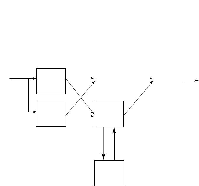
Redundancy System Overview |
Chapter 1 |
|
|
I/P
I/P
Duplex Architecture
An example configuration of dual input modules and adapters, and a single output module is shown in Figure 5. A redundant input or redundant output module provides fault tolerance for module failures. The duplex arrangement can be used for low demand and high demand applications.
Figure 5 - Duplex Architecture Duplex Inputs, Simplex Output
ADAPTER |
|
|
O/P |
|
|
||
|
|
|
|
ADAPTER
CIP NETWORK
CLX
Rockwell Automation Publication 1715-UM001C-EN-P - March 2014 |
23 |

Chapter 1 Redundancy System Overview
Figure 6 - Duplex Architecture Inputs and Outputs
I/P |
|
ADAPTER |
|
SENSORS
I/P |
|
ADAPTER |
|
CIP NETWORK
CLX
O/P
FINAL
ELEMENTS
O/P
|
|
1715- |
|
1715- |
|
|
|
TADIB16D |
TADIF16 |
||
1715-AENTR |
1715-AENTR |
1715-IB16D |
1715-IB16D |
1715-IF16 |
1715-IF16 |
1715-A2A |
|
1715-A3IO |
|
1715-A3IO |
|
Note that termination assemblies can span across I/O base units.
24 |
Rockwell Automation Publication 1715-UM001C-EN-P - March 2014 |
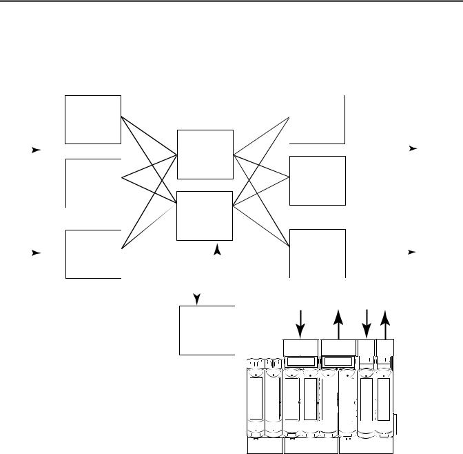
Redundancy System Overview Chapter 1
Mixed Architecture
There can be a mixture of architectures within one system. Figure 7 shows simplex and dual I/O configurations with dual processors.
Figure 7 - Mixed Architecture
SENSORS |
|
I/P |
O/P |
|
|
|
|
|||
|
|
|
|
|
|
|
FINAL |
|||
|
|
|
ADAPTER |
O/P |
|
|
|
|
ELEMENTS |
|
|
|
|
|
|
||||||
|
||||||||||
|
|
|
I/P |
|
|
|
||||
|
|
|
|
|||||||
ADAPTER
SENSORS |
|
|
O/P |
|
|
|
FINAL |
|
|
|
|
|
|
||||
|
I/P |
CIP NETWORK |
|
|
|
|
ELEMENTS |
|
|
|
|
|
|
|
|
|
|
|
|
|
|
|
|
|
|
|
|
|
|
|
|
|
|
|
|
CLX
|
|
1715- |
|
1715- |
|
1715- |
1715- |
|
|
|
TADIB16D |
TADOB8DE |
TASIB16D |
TASOB8DE |
|||
|
|
|
|
|||||
1715-AENTR |
1715-AENTR |
1715-IB16D |
1715-IB16D |
1715-OB8DE |
1715-OB8DE |
|
1715-IB16D |
1715-OB8DE |
1715-A2A |
|
1715-A3IO |
|
|
1715-A3IO |
|||
45423
Rockwell Automation Publication 1715-UM001C-EN-P - March 2014 |
25 |
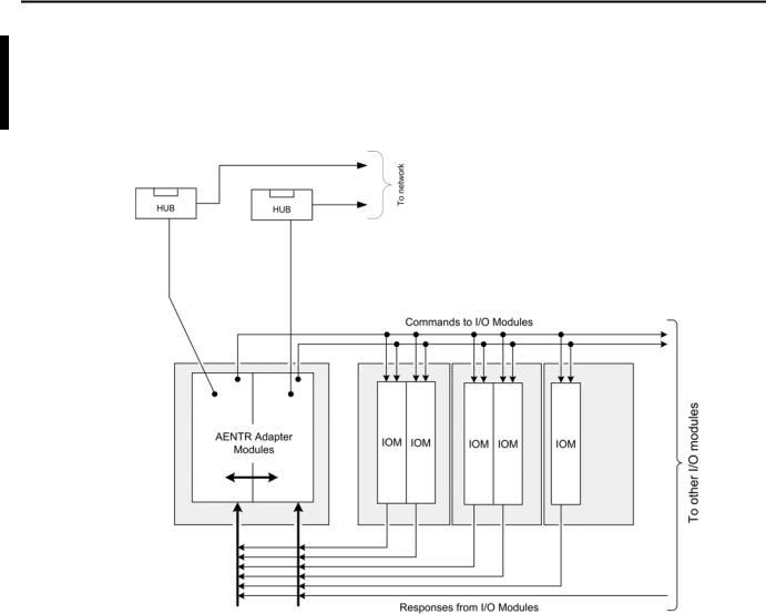
Chapter 1 Redundancy System Overview
Bus Diagram
A detailed drawing of the backplane is shown below.
Figure 8 - Bus Diagram of 1715 Redundant I/O System
26 |
Rockwell Automation Publication 1715-UM001C-EN-P - March 2014 |

|
Redundancy System Overview Chapter 1 |
|
|
|
|
|
|
Switchover Considerations |
Each 1715 Redundant I/O System uses a single IP address as the primary IP |
|
|
|
address for all communication on the EtherNet/IP network. The redundant |
|
|
|
adapter module pair consists of two active modules, a primary adapter module |
|
|
|
and its partner, a secondary module. For the purpose of this document, the |
|
|
|
primary module is referred to as module ‘A’ and the secondary module is referred |
|
|
|
to as module ‘B’. |
|
|
|
On power-up, the adapter module in the leftmost slot is considered the primary |
|
|
|
module (when two adapter modules are present) because it uses the primary IP |
|
|
|
address, and because it is the module responsible for receiving/transmitting to |
|
|
|
ControlLogix controller on the EtherNet/IP network. |
|
|
|
The module in the rightmost slot is considered the secondary module partner |
|
|
|
and uses the primary IP address +1. For example, if the primary module in the |
|
|
|
leftmost slot has an IP address of ‘N’, then the secondary module in the rightmost |
|
|
|
slot, has an IP address of ‘N+1’. |
|
|
|
Both modules are active at all times and are responsible for monitoring all inputs |
|
|
|
and outputs, monitoring diagnostics in the system, and reading and writing data |
|
|
|
from/to I/O at exactly the same time. When the primary module receives a write, |
|
|
|
it tells the secondary module the data that is to be written, and to which module |
|
|
|
it is to be written to. At a synchronized point in time, both adapter modules |
|
|
|
physically write to the I/O. |
|
|
|
The adapter modules negotiate which module is primary, depending on the |
|
|
|
status of the system. If the primary module is unable to perform its role, for |
|
|
|
example, if a fault occurs in the primary module, then the secondary module |
|
|
|
becomes the new primary, assuming the primary module’s IP address, taking over |
|
|
|
the role of communication. The primary module is the only module of the pair |
|
|
|
that produces data on the EtherNet/IP network. |
|
|
|
In the event of a fault, the IP address swapping between the primary module and |
|
|
|
the secondary module takes no longer than 20 ms from the time of the initiating |
|
|
|
fault. The secondary module is the new primary and handles all communication. |
|
|
|
(Depending on the structure of your Ethernet configuration, this time can be |
|
|
|
impacted.) |
|
|
|
This IP address swap is transparent to the user. The user can detect which module |
|
|
|
|
||
|
the primary module is by looking at the Network status indicator near the top of |
|
|
|
each adapter module. On the primary adapter the Network status indicator is |
|
|
|
solid green; on the secondary adapter, the Network status indicator flashes green. |
|
|
|
Once a swap occurs, the ‘new’ primary module remains the primary unless there’s |
|
|
|
a good reason to swap over again. If the B module becomes the primary module |
|
|
|
because you need to replace the A module, that is not enough cause to swap IP |
|
|
|
addresses back again. Module B remains as the primary module. |
|
|
Rockwell Automation Publication 1715-UM001C-EN-P - March 2014 |
27 |

Chapter 1 Redundancy System Overview
Obtaining a New IP Address
The primary module’s IP address is stored in the adapter base unit through interaction with the TCP/IP object. If a stored primary IP address is available, the adapter uses that address. If a stored primary IP address is not available, then the adapter uses BOOTP/DHCP to obtain an IP address.
The adapter transmits DHCP requests, but is able to process a BOOTP/DHCP response from either a DHCP or BOOTP server. If the BOOTP/DHCP request is unsuccessful, the secondary adapter module (that is, Module B), attempts to obtain the primary module’s IP address through BOOTP/DHCP.
The adapters continue to attempt BOOTP/DHCP configuration until an IP address is obtained, alternating between adapter Modules A and B. Once an adapter module has obtained the IP address, the secondary module can use that IP address + 1.
Once an adapter has a primary IP address, it confirms that it does not have a duplicate IP address. See EtherNet/IP Modules in Logix5000 Control Systems, publication ENET-UM001. Duplicated IP addresses are displayed by the Network Status indicator showing solid RED.
For additional information about assigning an IP address for the first time, see Chapter 2, Assign an IP Address on page 111.
28 |
Rockwell Automation Publication 1715-UM001C-EN-P - March 2014 |

Redundancy System Overview |
Chapter 1 |
|
|
Ethernet Topology
The 1715 Redundant I/O System supports DLR (Ring) and Star Topologies.
For a DLR (Ring) Topology, the adapter modules’ Ethernet ports are configured with the outward-facing ports (Port 1 of Module A and Port 2 of Module B) operating as a 2-port switch. Port 2 of Module A and Port 1 of Module B are chained together.
Figure 9 - DLR (Ring) Ethernet Topology
Module A
Port 1
Port 2
Module Status
Redundancy Status
 Network Status
Rack Status
Ethernet 1
1
Ethernet 2 |
Module Status
Redundancy Status
 Network Status
 Rack Status
Ethernet 1
1 
Ethernet 2 |
Module B
Port 1
Port 2
Reset |
Reset |
Rockwell Automation Publication 1715-UM001C-EN-P - March 2014 |
29 |

Chapter 1 Redundancy System Overview
For a STAR Topology, the adapter modules’ Ethernet ports are configured with the leftmost ports (Port 1 of Module A and Port 1of Module B) operating as a 2-port switch. The rightmost ports on each adapter are left unused.
Figure 10 - STAR Ethernet Topology
Module A
Port 1
Port 2
 Module Status
Redundancy Status
Network Status
Rack Status
Ethernet 1 |
Ethernet 2 |
Reset
 Module Status
Redundancy Status
Network Status
Rack Status
Ethernet 1 |
Ethernet 2 |
Reset 
Module B
Port 1
Port 2
45240
For Ethernet considerations, see EtherNet/IP Modules in Logix5000 Control Systems, publication ENET-UM001, and ControlLogix Enhanced Redundancy System, publication 1756-UM535.
Communication on the EtherNet/IP Network
Communication to a simplex module is addressed to the slot number for that module. CIP communication to modules in a duplex configuration (including the adapter modules) are addressed to the lowest slot number for the module pair.
The adapter modules respond with CIP errors for attempts to communicate to an I/O module of a type that is not the same as the physically installed module.
The termination assembly type (simplex/duplex) determines the CIP messages for corresponding CIP objects that the adapter processes for each I/O module.
30 |
Rockwell Automation Publication 1715-UM001C-EN-P - March 2014 |
Loading...