


1762-OF4
Table of contents
 Loading...
Installation Instructions
Analog Output Module
Catalog Number 1762-OF4
Table of Contents
Topic Page
Important User Information 2
North American Hazardous Location Approval 4
Additional Resources 5
Overview 6
Module Description 7
Mount the Module 8
Field Wiring Connections 11
Grounding the Module 11
Output Type Selection 11
Wiring the Finger-Safe Terminal Block 13
Specifications 18
2 Analog Output Module
Publication 1762-IN016D-EN-P - June 2013
Important User Information
Solid state equipment has operational characteristics differing from those of electromechanical equipment.
Safety Guidelines for the Application, Installation and Maintenance of Solid State Controls (Publication
SGI-1.1
available from your local Rockwell Automation sales office or online at
http://literature.rockwellautomation.com
) describes some important differences between solid state
equipment and hard-wired electromechanical devices. Because of this difference, and also because of the
wide variety of uses for solid state equipment, all persons responsible for applying this equipment must
satisfy themselves that each intended application of this equipment is acceptable.
In no event will Rockwell Automation, Inc. be responsible or liable for indirect or consequential damages
resulting from the use or application of this equipment.
The examples and diagrams in this manual are included solely for illustrative purposes. Because of the many
variables and requirements associated with any particular installation, Rockwell Automation, Inc. cannot
assume responsibility or liability for actual use based on the examples and diagrams.
No patent liability is assumed by Rockwell Automation, Inc. with respect to use of information, circuits,
equipment, or software described in this manual.
Reproduction of the contents of this manual, in whole or in part, without written permission of Rockwell
Automation, Inc., is prohibited.
Throughout this manual, when necessary, we use notes to make you aware of safety considerations.
WARNING
Identifies information about practices or circumstances that can cause an explosion in
a hazardous environment, which may lead to personal injury or death, property
damage, or economic loss.
IMPORTANT
Identifies information that is critical for successful application and understanding of
the product.
ATTENTION
Identifies information about practices or circumstances that can lead to personal injury
or death, property damage, or economic loss. Attentions help you identify a hazard,
avoid a hazard and recognize the consequences.
SHOCK HAZARD
Labels may be on or inside the equipment (for example, drive or motor) to alert people
that dangerous voltage may be present.
BURN HAZARD
Labels may be on or inside the equipment (for example, drive or motor) to alert people
that surfaces may reach dangerous temperatures.
Analog Output Module 3
Publication 1762-IN016D-EN-P - June 2013
Environment and Enclosure
Preventing Electrostatic Discharge
ATTENTION
This equipment is intended for use in a Pollution Degree 2 industrial
environment, in overvoltage Category II applications (as defined in IEC 60664-1),
at altitudes up to 2000 m (6562 ft) without derating.This equipment is
considered Group 1, Class A industrial equipment according to IEC/CISPR 11.
Without appropriate precautions, there may be difficulties with electromagnetic
compatibility in residential and other environments due to conducted and
radiated disturbances.
This equipment is supplied as open-type equipment. It must be mounted within
an enclosure that is suitably designed for those specific environmental
conditions that will be present and appropriately designed to prevent personal
injury resulting from accessibility to live parts. The enclosure must have suitable
flame-retardant properties to prevent or minimize the spread of flame,
complying with a flame spread rating of 5VA, V2, V1, V0 (or equivalent) if
non-metallic. The interior of the enclosure must be accessible only by the use of
a tool. Subsequent sections of this publication may contain additional
information regarding specific enclosure type ratings that are required to comply
with certain product safety certifications.
In addition to this publication, see:
• Industrial Automation Wiring and Grounding Guidelines, for additional installation
requirements, Allen-Bradley publication 1770-4.1
.
• NEMA Standards 250 and IEC 60529, as applicable, for explanations of the degrees
of protection provided by different types of enclosure.
ATTENTION
This equipment is sensitive to electrostatic discharge, which can cause internal
damage and affect normal operation. Follow these guidelines when you handle
this equipment:
• Touch a grounded object to discharge potential static.
• Wear an approved grounding wriststrap.
• Do not touch connectors or pins on component boards.
• Do not touch circuit components inside the equipment.
• Use a static-safe workstation, if available.
• Store the equipment in appropriate static-safe packaging when not in use.
4 Analog Output Module
Publication 1762-IN016D-EN-P - June 2013
North American Hazardous Location Approval
The following modules are North American Hazardous Location approved: 1762-OF4
The following information applies when
operating this equipment in hazardous
locations:
Informations sur l’utilisation de cet
équipement en environnements dangereux:
Products marked "CL I, DIV 2, GP A, B, C, D" are
suitable for use in Class I Division 2 Groups A, B, C,
D, Hazardous Locations and nonhazardous
locations only. Each product is supplied with
markings on the rating nameplate indicating the
hazardous location temperature code. When
combining products within a system, the most
adverse temperature code (lowest "T" number) may
be used to help determine the overall temperature
code of the system. Combinations of equipment in
your system are subject to investigation by the
local Authority Having Jurisdiction at the time of
installation.
Les produits marqués "CL I, DIV 2, GP A, B, C, D" ne
conviennent qu'à une utilisation en environnements de
Classe I Division 2 Groupes A, B, C, D dangereux et non
dangereux. Chaque produit est livré avec des
marquages sur sa plaque d'identification qui indiquent
le code de température pour les environnements
dangereux. Lorsque plusieurs produits sont combinés
dans un système, le code de température le plus
défavorable (code de température le plus faible) peut
être utilisé pour déterminer le code de température
global du système. Les combinaisons d'équipements
dans le système sont sujettes à inspection par les
autorités locales qualifiées au moment de l'installation.
WARNING
EXPLOSION HAZARD
• Do not disconnect equipment
unless power has been removed or
the area is known to be
nonhazardous.
• Do not disconnect connections to
this equipment unless power has
been removed or the area is known
to be nonhazardous. Secure any
external connections that mate to
this equipment by using screws,
sliding latches, threaded
connectors, or other means
provided with this product.
• Substitution of components may
impair suitability for Class I,
Division 2.
• If this product contains batteries ,
they must only be changed in an
area known to be nonhazardous.
• All wiring must comply with N.E.C.
article 501-4(b).
• The interior of the enclosure must
be accessible only by the use of a
tool.
• For applicable equipment (relay
modules, etc.), exposure to some
chemicals may degrade the sealing
properties of materials used in the
following devices: Relays, Epoxy. It
is recommended that the User
periodically inspect these devices
for any degradation of properties
and replace the module if
degradation is found.
AVERTISSEMENT
RISQUE D’EXPLOSION
• Couper le courant ou s’assurer que
l’environnement est cl assé non
dangereux avant de débrancher
l'équipement.
• Couper le courant ou s'assurer que
l'environnement est classé non
dangereux avant de débrancher les
connecteurs. Fixer tous les connecteurs
externes reliés à cet équipement à
l'aide de vis, loquets coulissants,
connecteurs filetés ou autres moye ns
fournis avec ce produit.
• La substitution de composants peut
rendre cet équipement inadapté à u ne
utilisation en environnement de Classe
I, Division 2.
• S’assurer que l’environnement est
classé non dangereux avant de changer
les piles.
Analog Output Module 5
Publication 1762-IN016D-EN-P - June 2013
Additional Resources
If you would like a manual, you can:
• download a free electronic version from the Internet:
http://literature.rockwellautomation.com
• purchase a printed manual by contacting your local Allen-Bradley distributor or
Rockwell Automation representative
Resource Description
MicroLogix 1100 Programmable Controllers User
Manual, publication 1763-UM001
.
A more detailed description of how to install and use
your MicroLogix 1100 programmable controller and
expansion I/O system.
MicroLogix 1200 Programmable Controllers User
Manual, publication 1762-UM001
.
A more detailed description of how to install and use
your MicroLogix 1200 programmable controller and
expansion I/O system.
MicroLogix 1400 Programmable Controllers User
Manual, publication 1766-UM001
.
A more detailed description of how to install and use
your MicroLogix 1400 programmable controller and
expansion I/O system.
MicroLogix 1100 Programmable Controllers
Installation Instructions, publication 1763-IN001
.
Information on installing and using the
MicroLogix 1100 programmable controller.
MicroLogix 1200 Programmable Controllers
Installation Instructions, publication 1762-IN006
.
Information on installing and using the
MicroLogix 1200 programmable controller.
MicroLogix 1400 Programmable Controllers
Installation Instructions, publication 1766-IN001
.
Information on installing and using the
MicroLogix 1400 programmable controller.
Industrial Automation Wiring and Grounding
Guidelines, publication 1770-4.1
.
More information on proper wiring and grounding
techniques.
6 Analog Output Module
Publication 1762-IN016D-EN-P - June 2013
Overview
1762 output module is suitable for use in an industrial environment when installed in
accordance with these instructions. Specifically, this equipment is intended for use in clean, dry
environments (Pollution degree 2
(1)
) and to circuits not exceeding Over Voltage Category II
(2)
(IEC 60664-1)
(3)
.
Install your module using these installation instructions.
1762 Output Module
(1)
Pollution Degree 2 is an environment where, normally, only non-conductive pollution occurs except that occasionally a
temporary conductivity caused by condensation shall be expected.
(2)
Over Voltage Category II is the load level section of the electrical distribution system. At this level transient voltages are
controlled and do not exceed the impulse voltage capability of the product’s insulation.
(3)
Pollution Degree 2 and Over Voltage Category II are International Electrotechnical Commission (IEC) designations.
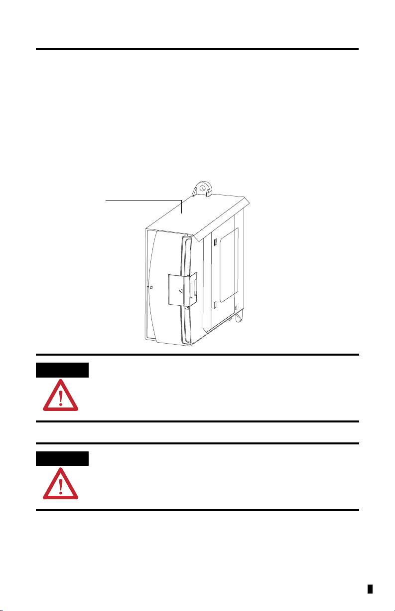
ATTENTION
Do not remove the protective debris strip until after the module and all other
equipment in the panel near the module are mounted and wiring is complete.
Once wiring is complete, remove protective debris strip. Failure to remove strip
before operating can cause overheating.
ATTENTION
Electrostatic discharge can damage semiconductor devices inside the module.
Do not touch the connector pins or other sensitive areas.
Debris strip
45155
Analog Output Module 7
Publication 1762-IN016D-EN-P - June 2013
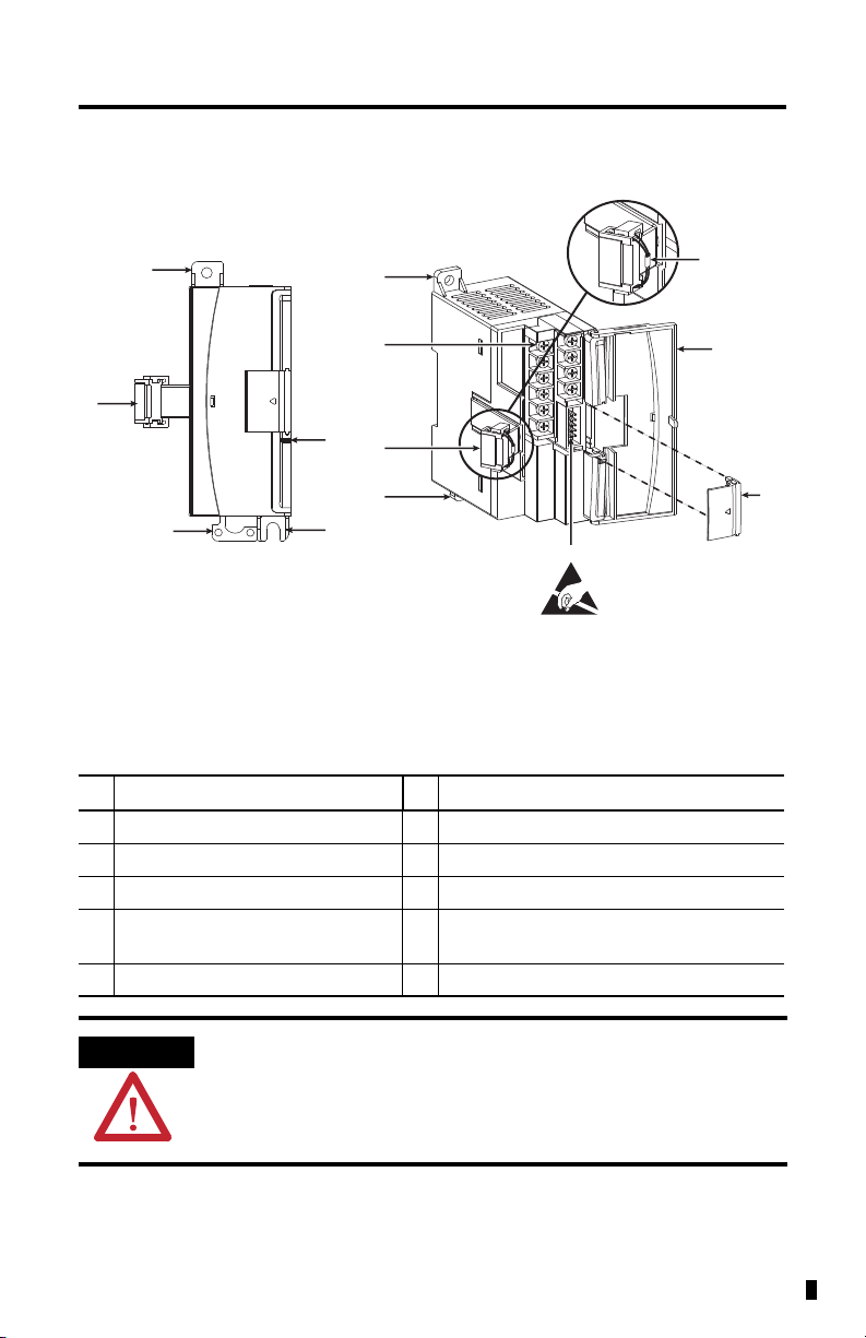
Module Description
Description Description
1a upper panel mounting tab 5 pull loop
1b lower panel mounting tab 6 module door with terminal identification label
2 power diagnostic LED 7 bus connector cover
3 flat ribbon cable with bus connector
(female)
8 bus connector
with male pins
4 DIN rail latch 9 terminal block
ATTENTION
To comply with UL restrictions, this equipment must be powered from a source
compliant with Class 2 or Limited Voltage/Current.
1a
4
7
8
6
3
9
5
Left side view
Front view
This equipment is sensitive to electrostatic discharge (ESD).
Follow ESD prevention guidelines when handling this equipment.
45180
1a
1b
3
4
2
45156
8 Analog Output Module
Publication 1762-IN016D-EN-P - June 2013
Mount the Module
General Considerations
Most applications require installation in an industrial enclosure to reduce the effects of electrical
interference and environmental exposure. Locate your controller as far as possible from power
lines, load lines, and other sources of electrical noise such as hard-contact switches, relays, and
AC motor drives. For more information on proper grounding guidelines, see the Industrial
Automation Wiring and Grounding Guidelines, publication 1770-4.1
.
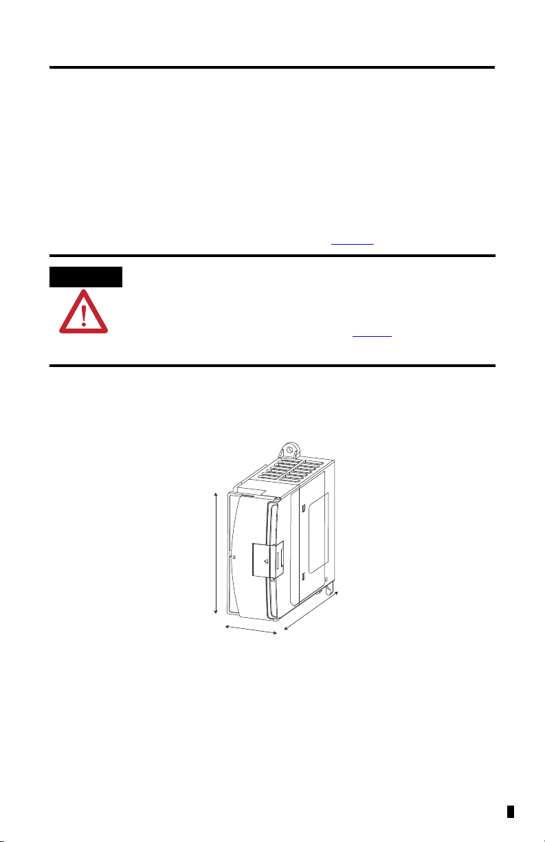
Mounting Dimensions
ATTENTION
This product is intended to be mounted to a well-grounded mounting surface
such as a metal panel. Additional grounding connections from the power
supply's mounting tabs or DIN rail (if used) are not required unless the mounting
surface cannot be grounded. Refer to Industrial Automation Wiring and
Grounding Guidelines, Allen-Bradley publication 1770-4.1
, for additional
information.
45158
Measurements do not include mounting feet or DIN rail latches.
90 mm
(3.5 in.)
87 mm
(3.43 in.)
40.4 mm (1.59 in.)
Loading...