


 Loading...
SLC500FastAnalog
I/O Module
Catalog Numbers 1746-FIO4I and
1746-FIO4V
User Manual

Important User Information Solid state equipment has operational characteristics differing from those of electromechanical equipment. Safety Guidelines for the Application,
Installation and Maintenance of Solid State Controls (publication SGI-1.1 available from your local Rockwell Automation sales office or online at http://literature.rockwellautomation.com) describes some important differences between solid state equipment and hard-wired electromechanical devices. Because of this difference, and also because of the wide variety of uses for solid state equipment, all persons responsible for applying this equipment must satisfy themselves that each intended application of this equipment is acceptable.
In no event will Rockwell Automation, Inc. be responsible or liable for indirect or consequential damages resulting from the use or application of this equipment.
The examples and diagrams in this manual are included solely for illustrative purposes. Because of the many variables and requirements associated with any particular installation, Rockwell Automation, Inc. cannot assume responsibility or liability for actual use based on the examples and diagrams.
No patent liability is assumed by Rockwell Automation, Inc. with respect to use of information, circuits, equipment, or software described in this manual.
Reproduction of the contents of this manual, in whole or in part, without written permission of Rockwell Automation, Inc., is prohibited.
Throughout this manual, when necessary, we use notes to make you aware of safety considerations.
|
|
|
|
|
|
|
Identifies information about practices or circumstances that can cause |
|
WARNING |
||||||||
|
an explosion in a hazardous environment, which may lead to personal |
|||||||
|
|
|
|
|
|
|
||
|
|
|
|
|
|
|
injury or death, property damage, or economic loss. |
|
|
|
|
|
|
|
|
|
|
|
|
|
|
|
|
|
|
|
|
|
|
|
|
|
|
|
|
|
|
|
|
|
|
|
Identifies information that is critical for successful application and |
|
IMPORTANT |
|
|||||||
|
understanding of the product. |
|||||||
|
|
|
|
|
|
|
||
|
|
|
|
|
|
|
|
|
|
|
|
|
|
|
|
Identifies information about practices or circumstances that can lead |
|
ATTENTION |
|
|||||||
|
to personal injury or death, property damage, or economic loss. |
|||||||
|
|
|
|
|
|
|
||
|
|
|
|
|
|
|
Attentions help you identify a hazard, avoid a hazard, and recognize |
|
|
|
|
|
|
|
|
the consequence |
|
|
|
|
|
|
|
|
||
|
|
|
|
|
|
|
||
|
|
|
|
|
|
|
||
|
|
|
|
|
|
|
Labels may be on or inside the equipment, for example, a drive or |
|
SHOCK HAZARD |
|
|||||||
|
|
|
|
|
|
|
motor, to alert people that dangerous voltage may be present. |
|
|
|
|
|
|
||||
|
|
|
|
|
|
|
||
|
|
|
||||||
|
|
|
|
|
|
|
Labels may be on or inside the equipment, for example, a drive or |
|
BURN HAZARD |
|
|||||||
|
|
|
|
|
|
|
motor, to alert people that surfaces may reach dangerous |
|
|
|
|
|
|
|
|
||
|
|
|
|
|
|
|
temperatures. |
|
|
|
|
|
|
|
|
|
|
|
|
|
|
|
|
|
|
|
Rockwell Automation, Allen-Bradley, TechConnect, RSLogix500, SLC, SLC 500, and SLC 5/02 are trademarks of Rockwell
Automation, Inc.
Trademarks not belonging to Rockwell Automation are property of their respective companies.

Table of Contents
Preface
About This Publication . . . . . . . . . . . . . . . . . . . . . . . . . . . . . 5
Who Should Use This Manual . . . . . . . . . . . . . . . . . . . . . . . . 5
Additional Resources. . . . . . . . . . . . . . . . . . . . . . . . . . . . . . . 6
Conventions . . . . . . . . . . . . . . . . . . . . . . . . . . . . . . . . . . . . . 6
|
Chapter 1 |
|
Quick Start |
Required Tools and Equipment . . . . . . . . . . . . . . . . . . . . . . |
. 7 |
|
Procedures . . . . . . . . . . . . . . . . . . . . . . . . . . . . . . . . . . . . . . |
8 |
|
Chapter 2 |
|
Install and Wire the Modules |
Determine the Module’s Power Requirements . . . . . . . . . . . |
11 |
|
Determine Compatibility with Other I/O Modules. . . . . . . . . |
12 |
|
Configure Input Channels . . . . . . . . . . . . . . . . . . . . . . . . . . |
13 |
|
Select the I/O Rack Slot. . . . . . . . . . . . . . . . . . . . . . . . . . . . |
14 |
|
Install the Module . . . . . . . . . . . . . . . . . . . . . . . . . . . . . . . . |
14 |
|
Considerations When Wiring . . . . . . . . . . . . . . . . . . . . . . . . |
16 |
|
Minimize Electrical Noise Interference . . . . . . . . . . . . . . . . . |
18 |
|
Wire the Module . . . . . . . . . . . . . . . . . . . . . . . . . . . . . . . . . |
18 |
|
Minimize Ground Loops . . . . . . . . . . . . . . . . . . . . . . . . . . . |
20 |
|
Label the Terminal Block. . . . . . . . . . . . . . . . . . . . . . . . . . . |
21 |
|
Chapter 3 |
|
Access Files to Configure I/O |
Click and Drag Configuration . . . . . . . . . . . . . . . . . . . . . . . |
23 |
|
Read IO Config Method. . . . . . . . . . . . . . . . . . . . . . . . . . . . |
24 |
|
Chapter 4 |
|
Processor and Module
Considerations
Write Ladder Logic
Processor Considerations. . . . . . . . . . . . . . . . . . . . . . . . . . . 30
Module Considerations . . . . . . . . . . . . . . . . . . . . . . . . . . . . 32
Chapter 5
Retentive and Non-retentive Programming . . . . . . . . . . . . . . 39 Detect an Out-of-range Input. . . . . . . . . . . . . . . . . . . . . . . . 41 Overview of Scaling Inputs and Outputs . . . . . . . . . . . . . . . 42 Scale an Analog Input and Detect an Out-of-range Condition 44 Scale an Analog Output. . . . . . . . . . . . . . . . . . . . . . . . . . . . 47 Scale Offsets When >32,767 or <32,768. . . . . . . . . . . . . . . . 49 Range-check an Analog Input and Scale It for an Output . . . 52 PID Control with Analog I/O Scaling . . . . . . . . . . . . . . . . . . 56
Publication 1746-UM009B-EN-P - September 2007

4 Table of Contents |
|
|
|
Chapter 6 |
|
Calibrate the Module |
Calibration Tradeoffs . . . . . . . . . . . . . . . . . . . . . . . . . . . . . . |
61 |
|
Calibrate an Analog Input Channel . . . . . . . . . . . . . . . . . . . |
62 |
|
Chapter 7 |
|
Test Module Operation |
Test the SLC 500 System . . . . . . . . . . . . . . . . . . . . . . . . . . . |
67 |
|
Test the Module . . . . . . . . . . . . . . . . . . . . . . . . . . . . . . . . . |
67 |
|
Chapter 8 |
|
Maintenance and Safety |
Preventive Maintenance. . . . . . . . . . . . . . . . . . . . . . . . . . . . |
75 |
|
Safety Considerations When Troubleshooting . . . . . . . . . . . . |
76 |
|
Appendix A |
|
Module Specifications |
General Description . . . . . . . . . . . . . . . . . . . . . . . . . . . . . . |
77 |
|
Specifications . . . . . . . . . . . . . . . . . . . . . . . . . . . . . . . . . . . |
77 |
|
Appendix B |
|
2’s-complement Binary Numbers |
Use 2’s-complement Binary Numbers. . . . . . . . . . . . . . . . . . |
83 |
|
Appendix C |
|
Module Input and Output Circuits |
. . . . . . . . . . . . . . . . . . . . . . . . . . . . . . . . . . . . . . . . . . . . . |
87 |
|
Index |
|
Publication 1746-UM009B-EN-P - September 2007

Preface
About This Publication
Who Should Use This
Manual
Read this preface to familiarize yourself with the rest of the manual. This preface covers the following topics:
•Who should use this manual
•The purpose of this manual
•Terms and abbreviations
•Conventions used in this manual
•Allen-Bradley support
This manual is a reference guide for the 1746-NR4 RTD/Resistance Input Module. The manual:
•gives you an overview of system operation.
•explains the procedures you need to install and wire the module at the customer site.
•provides ladder programming examples.
•provides an application example of how this input module can be used to control a process.
Use this manual if you are responsible for designing, installing, programming, or troubleshooting control systems that use Allen-Bradley small logic controllers.
You should have a basic understanding of SLC 500 products. You should understand programmable controllers and be able to interpret the ladder logic instructions required to control your application. If you do not, contact your local Allen-Bradley representative for information on available training courses before using this product.
Publication 1746-UM009B-EN-P - September 2007

6 Preface
Additional Resources
The following documents contain information that may be helpful to you as you use Allen-Bradley SLC products.
Resource |
Description |
|
|
SLC 500 Systems Selection Guide, publication 1747-SG001 |
An overview of the SLC 500 family of products |
|
|
SLC 500 Module Hardware Style User Manual, publication |
A description on how to install and use your modular SLC 500 |
1747-UM011 |
programmable controller |
|
|
Installation & Operation Manual for Fixed Hardware Style |
A description on how to install and use your fixed SLC 500 |
Programmable Controllers, publication 1747-6.21 |
programmable controller |
|
|
SLC 500 Instruction Set Reference Manual, publication |
A reference manual that contains status file data, instruction set, |
1747-RM001 |
and troubleshooting information about the software |
|
|
SLC 500 4-Channel Analog I/O Modules User’s Manual, publication |
A resource manual and user’s guide containing information about |
1746-UM005 |
the analog modules used in your SLC 500 system. |
|
|
Industrial Automation Wiring and Grounding Guidelines, publication |
In-depth information on grounding and wiring Allen-Bradley |
1770-4.1 |
programmable controllers |
|
|
Application Considerations for Solid-State Controls. publication |
A description of important differences between solid-state |
SGI-1.1 |
programmable controller products and hard-wired |
|
electromechanical devices |
|
|
National Electrical Code, published by the National Fire Protection |
An article on wire sizes and types for grounding electrical |
Association of Boston, MA |
equipment |
|
|
Conventions
You can view or download publications at http://literature.rockwellautomation.com. To order paper copies of technical documentation, contact your local Rockwell Automation distributor or sales representative.
The following conventions are used throughout this manual:
•Bulleted lists such as this one provide information, not procedural steps.
•Numbered lists provide sequential steps or hierarchical information.
Publication 1746-UM009B-EN-P - September 2007

Chapter 1
Required Tools and
Equipment
Quick Start
This chapter presents an overview of installation and start-up procedures to help you get the module working quickly.
It refers to full procedures in corresponding chapters of this manual or in other SLC documentation that may be helpful if you are unfamiliar with programming techniques or system installation.
We recommend that you use this chapter in either of two ways.
•Use as a fast installation and start-up guide for the experienced users.
•Use as an overview for using the entire manual for the first-time user.
|
If you have any questions about the abbreviated procedures |
|
IMPORTANT |
||
presented in this chapter, always read the referenced chapters |
||
|
||
|
||
|
and other recommended documentation before trying to apply |
|
|
the information. |
|
|
|
Have the following tools and equipment ready.
•Medium flat-head screwdriver
•Medium Phillips-head screwdriver
•Wire strippers
•Utility knife
•Hot-air blower
•Shrink wrap
•Belden 8761 cable or equivalent
•Analog I/O devices for your application
•I/O modules (1746-FIO4I and/or 1746-FIO4V)
•Programming software
Publication 1746-UM009B-EN-P - September 2007
8 Quick Start
Procedures
Follow these steps to get your module running in your SLC system.
1.Plan the inclusion of analog I/O modules in your SLC system.
If a new system, specify the type of processor, number of I/O racks, I/O modules, and power supply. If adding to an existing system:
•assign modules to slot locations in the I/O rack.
•verify that the power supply for the I/O rack can handle the increased load.
See SLC 500 Systems Selection Guide, publication 1747-SG001, for more information.
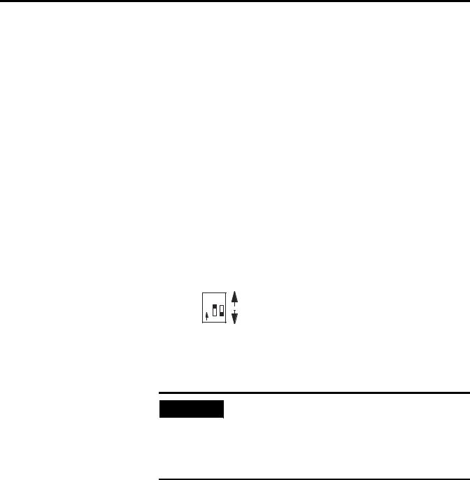
2.Configure module input channels for current or voltage operation.
Locate the 2-switch assembly on the module’s circuit board, and set each channel as follows.
Current (ON) |
|
O 1 2 |
Switch 1 = Channel 0 |
N |
Switch 2 = Channel 1 |
|
|
Voltage (OFF) |
|
3. Connect I/O devices with cables.
• Connect only one end of the cable shield to earth ground.
IMPORTANT
• Channels are not isolated from each other. All analog commons are connected together internally.
• The module does not provide loop power for analog inputs.
• Use a power supply that matches the transmitter (sensor) specifications.
Refer to Install and Wire the Modules on page 11.
Publication 1746-UM009B-EN-P - September 2007
Quick Start |
9 |
|
|
For Differential Inputs |
|
|
|
||
Analog |
+ |
|
Module |
|
|
|
0 |
IN 0 + |
|||
Sensor |
– |
|
|||
|
1 |
IN 0 – |
|||
|
|
|
|||
|
Earth |
|
2 |
ANL COM |
|
|
Ground |
Important: Jumper |
3 |
IN 1 + |
|
|
|
||||
|
|
4 |
IN 1 – |
||
|
|
unused inputs. |
|||
|
|
5 |
ANL COM |
||
|
|
|
|||
Load |
|
|
6 |
Not Used |
|
|
|
7 |
OUT 0 |
||
|
|
|
|||
|
|
Earth |
8 |
ANL COM |
|
|
|
9 |
Not Used |
||
|
|
Ground |
|||
|
|
Important: Do not |
10 |
OUT 1 |
|
For Single-ended Input |
11 |
ANL COM |
|||
jumper unused outputs. |
|||||
with 3-wire Transmitter |
|
|
|||
|
|
|
|||
|
Transmitter |
|
|
||
|
Supply |
Signal |
Module |
|
|
|
|
GND |
|
|
|
Power |
+ |
|
3 |
IN + |
|
Supply |
– |
|
4 |
IN – |
|
|
|
|
5 |
ANL COM |
|
4.Configure the system I/O and module ID.
With the software, configure the processor, I/O racks, slots, and I/O modules.
When assigning an I/O module to a slot location, select the module from the displayed list. If not listed, select OTHER at the bottom of the list and enter the module’s ID code at the prompt.
ID code for 1746-FIO4I is 3224 ID code for 1746-FIO4V is 3218
5.Understand A/D & D/A converter resolution on input and output words.
The module’s I/O channel converters limit bit usage to less than a full 16-bit word.
The input channel converter resolution is 12 bits, where the highest four bits are always zero.
The output channel converter resolution is 14 bits, where the lowest two bits are never used.
Publication 1746-UM009B-EN-P - September 2007

10 Quick Start
The lowest two bits have no effect on the output value.
Refer to Processor and Module Considerations on page 29 for more information.
SLC 500 Processor
Data Files
|
Input Image |
|
Output Image |
|
|
|
|
|
|
|
|
|
|
|
|
|
|
|
|
|
|
|
(2 words) |
|
(2 words) |
|
|
|
|
|
|
|
|
|
|
|
|
|
|
|
|
|
|
Address |
|
|
|
msb |
(variable input data) |
|
lsb |
|
|
|
|
|
|||||||||
I:1.0 |
Channel 0 Input Word |
0 0 0 |
0 |
|
|
|
|
|
|
|
|
|
|
|
|
|
|
|
|
|
|
I:1.1 |
Channel 1 Input Word |
|
Bit 15 |
|
Bit 11 |
|
|
|
|
|
|
|
|
Bit 0 |
|
|
|
|
|
|
|
|
Address |
|
|
|
|
|
msb |
variable output data) |
|
lsb |
|||||||||||
|
O:1.0 |
Channel 0 Output Word |
|
|
|
|
|
|
|
|
|
|
|
|
|
|
|
|
X |
X |
|
|
O:1.1 |
Channel 1 Output Word |
|
|
|
Bit 15 |
|
|
|
|
|
|
|
Bit 2 |
Bit 0 |
||||||
|
|
|
|
|
|
|
|
|
|
|
|
|
|
|
|
|
X = not used |
||||
6.Write ladder logic to process the module’s analog data.
We provide several programming examples that include the following:
•Clear the output when changing mode or cycling power
•Detect an out-of-range input
•Scale analog outputs
•Scale offsets
•Scale and range-check analog inputs and outputs
•PID control with analog I/O scaling
Study these examples to understand how to program the module.
Refer to Write Ladder Logic on page 39.
7.(Optional) Write ladder logic to maintain calibrated inputs.
We show you how to write ladder logic that provides a calibrated input reference during runtime, and lets you periodically calibrate module inputs. We suggest that you modify the logic examples to suit your application and add them to your application program.
Refer to Calibrate the Module on page 61 for more information.
Publication 1746-UM009B-EN-P - September 2007
Chapter 2
Determine the Module’s
Power Requirements
Install and Wire the Modules
This chapter describes procedures to install fast analog I/O modules in an SLC 500 system. The procedures include the following tasks.
•determine the module’s power requirements
•determine compatibility with other I/O modules
•configure input channels
•select the I/O rack slot
•install the module
•consider when wiring
–using system wiring guidelines
–grounding the cable
–determining cable length
•minimize electrical noise interference
•wire the module
•minimize ground loops
•label the terminal block
Analog modules require power from the 5V dc and 24V dc backplane power supplies of the SLC 500 system. This table shows the backplane power requirements for fast analog I/O modules.
Current Load
Catalog Number |
Current at 5V dc |
Current at 24V dc |
|
|
|
1746-FIO4I |
55 mA |
150 mA |
|
|
|
1746-FIO4V |
55 mA |
120 mA |
|
|
|
Use this table to compute the module’s portion of total load on the modular system power supply.
For more information, refer to SLC 500 Systems Selection Guide, publication 1747-SG001.
Publication 1746-UM009B-EN-P - September 2007

12 Install and Wire the Modules
Determine Compatibility with Other I/O Modules
Use the I/O Compatibility chart when using the expansion rack of a fixed controller (1747-L20, 1747-L30, and 1747-L40). The chart determines compatibility of other I/O modules with fast analog modules. Compatibility is solely based on current drawn from the backplane.
For more information, refer to the SLC 500 Fixed Hardware Style Installation and Operation Manual, publication 1747-6.21.
I/O Compatibility
1746-FIO4I |
1746-FIO4V |
1746 Module |
|
|
|
|
|
FIO4I |
|
|
|
|
|
FIO4V |
|
|
|
•(1) |
• |
IA4, IA8, IA16 |
• |
• |
IB8, IB16 |
|
|
|
• |
• |
IB32 |
|
|
|
• |
• |
IG16 |
|
|
|
• |
• |
IM4, IM8, IM16 |
|
|
|
• |
• |
IN16 |
|
|
|
• |
• |
IO4 |
|
|
|
|
• |
IO8 |
|
|
|
|
|
IO12 |
|
|
|
• |
• |
ITB16, ITV16 |
|
|
|
• |
• |
IV8, IV16, IV32 |
|
|
|
|
|
NIO4I, NIO4V |
|
|
|
(2) |
|
NO4I, NO4V |
|
|
NI4 |
|
|
|
• |
• |
NR4 |
|
|
|
• |
• |
NT4 |
|
|
|
• |
• |
OA8 |
|
|
|
|
|
OA16 |
|
|
|
• |
• |
OB8 |
|
|
|
|
|
OB16, OB32 |
|
|
|
|
• |
OBP16 |
|
|
|
• |
• |
OG16 |
|
|
|
• |
• |
OV8 |
|
|
|
|
• |
OV16 |
|
|
|
|
|
OV32 |
|
|
|
Publication 1746-UM009B-EN-P - September 2007
Install and Wire the Modules |
13 |
|
|
I/O Compatibility
1746-FIO4I |
1746-FIO4V |
1746 Module |
|
|
|
|
• |
OW4 |
|
|
|
|
|
OW8, OW16 |
|
|
|
|
|
OX8 |
|
|
|
|
• |
BASIC |
|
|
|
|
|
BASn |
|
|
|
|
|
DCM |
|
|
|
|
|
HS |
|
|
|
|
• |
KE |
|
|
|
|
|
KEn |
|
|
|
(1)The • symbol indicates an allowable combination of 1746 I/O modules.
(2)The symbol indicates an auxiliary 24V dc power supply may be needed.
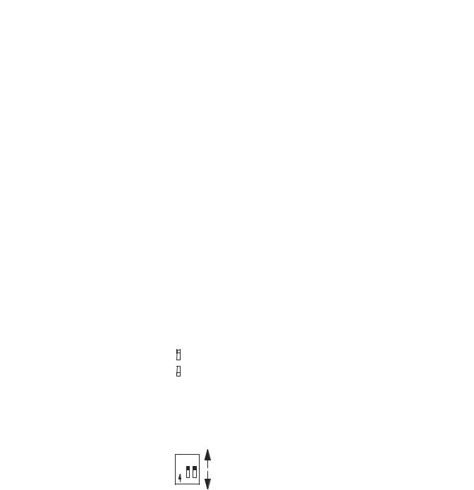
Configure Input Channels |
Your fast analog I/O modules have a two-switch assembly to |
||
|
configure the input channels for either current or voltage operation. |
||
|
The switches are on the module’s circuit board. Switch orientation is |
||
|
shown on the nameplate of the module. |
||
|
Switch Orientation |
||
|
|
|
ON – Configures channel for current input |
|
|
|
|
|
|
|
|
|
|
|
OFF – Configures channel for voltage input |
|
|
|
|
|
Switches labeled 1 and 2 control the input mode of channels 0 and 1 |
||
|
respectively. |
||
Channels 0 and 1 Input Mode
Current (ON) |
|
O 1 2 |
Switch 1 = Channel 0 |
N |
Switch 2 = Channel 1 |
|
|
Voltage (OFF) |
|
Publication 1746-UM009B-EN-P - September 2007

14 Install and Wire the Modules
Select the I/O Rack Slot
Install the Module
Two factors determine where you should locate the module in the I/O rack: ambient temperature and electrical noise. Consider the following conditions when selecting an I/O rack slot for the module. Position the module:
•in a slot away from ac or high voltage dc modules.
•away from the rack power supply if installed in a modular system.
•in the I/O rack lowest in the enclosure for a cooler ambient.
When installing the module in an I/O rack, you do not need to remove the terminal block from the module. However, if the terminal block is removed, use the write-on label located on the side of the terminal block to identify the module location and type. To remove the terminal block, grasp it on the top and bottom and pull outward and down.
ATTENTION |
|
Never install, remove, or wire modules with power applied to |
||
|
the I/O rack. Rid yourself of electrostatic charge before |
|||
|
|
|
|
|
|
|
|
||
|
|
|
|
handling the module. Electrostatic discharge can degrade |
|
|
|
|
module performance or destroy analog circuitry. |
|
|
|
|
|
|
|
|
|
|
|
|
|
|
|
|
|
|
|
Do not tamper with the module’s factory-sealed potentiometer. |
IMPORTANT |
|
|||
|
It does not require any adjustments. |
|||
|
|
|
|
|
|
|
|
|
|
|
|
|
|
|
Follow these steps when installing or removing the module.
1. Verify that input configuration switches 1 and 2 are set correctly.
ATTENTION |
Take care to avoid connecting a voltage source to a channel |
|||
configured for current input. This could result in improper |
||||
|
|
|
||
|
|
|
||
|
|
|
module operation or damage to the module. |
|
|
|
|
|
|
|
|
|
|
|
|
|
|
|
|
2.Align the module’s circuit board with the rack’s card guide. See Installing the Module on page 15.
3.Slide the module in until top and bottom retaining clips are secured.
Publication 1746-UM009B-EN-P - September 2007

Install and Wire the Modules |
15 |
|
|
4.To remove the module, press the retaining clips at the top and bottom of the module and slide the module out.
Installing the Module
Card Guide
Self-locking tabs secure the module in the I/O rack.
Publication 1746-UM009B-EN-P - September 2007

16 Install and Wire the Modules
Considerations When
Wiring
This section provides guidelines on wiring the system, grounding the cables, determining cable length.
ATTENTION |
Before wiring the module, disconnect SLC system power, I/O |
|||
rack power, and module power. |
||||
|
|
|
||
|
|
|
||
|
|
|
|
|
|
|
|
|
|
|
|
|
|
|
System Wiring Guidelines
Use the following guidelines in planning the system wiring to the module.
•Analog common terminals (ANL COM) are electrically interconnected inside the module, but not internally connected to earth.
•Voltages on IN+ and IN– terminals must be within 0…20V with respect to ANL COM to ensure proper input channel operation. This is true for current and voltage input channel operation.
•Voltage outputs (OUT 0 and OUT 1) of the 1746-FIO4V module
are referenced to ANL COM. Load resistance (R1) for a voltage output channel must be equal to or greater than 1 KΩ.
•Current output channels (OUT 0 and OUT 1) of the 1746-FIO4I
module source current that returns to ANL COM. Load resistance (R1) for a current output channel must be within 0…500 Ω.
•Input connections for single-ended or differential input are the same.
Publication 1746-UM009B-EN-P - September 2007
Install and Wire the Modules |
17 |
|
|
Ground the Cable
Signal cable such as Belden cable #8761 (or equivalent) has two signal wires (black and clear), one drain wire, and a foil shield. The drain wire and foil shield must be grounded at only one end of the cable, not at both ends.
Typical Signal Cable
|
Foil Shield |
Shrink Wrap |
Black Wire |
|
|
Insulation |
|
Clear Wire |
Drain Wire |
|
Ground the cable shield at one end having a good earth-ground |
|
IMPORTANT |
||
connection, such as at an I/O chassis mounting bolt or nearest |
||
|
||
|
||
|
ground bus in the I/O enclosure. Make this connection as short |
|
|
as possible. Do not ground the cable at the module’s terminal |
|
|
block. |
|
|
|
Determine Cable Length
When you determine the length of cable required to connect an I/O device, remember to include additional length to route the drain wire and foil shield to earth ground. Route your cable long enough to avoid areas of high radiated electrical noise, but short enough to avoid signal attenuation.
Publication 1746-UM009B-EN-P - September 2007

18 Install and Wire the Modules
Minimize Electrical Noise
Interference
Wire the Module
Because high-speed analog signals are particularly vulnerable to electrical noise, take precautions when routing your signal cables. To help reduce the effects of electrical noise on analog signals, we recommend that you do the following:
•Install the SLC 500 system in a NEMA rated enclosure.
•Make sure that the SLC 500 system is properly grounded.
•Use Belden cable #8761 (or equivalent) for signal wiring.
•Ground the cable properly.
•Route signal cables away from other wiring or in grounded conduit.
•Group these modules away from ac or high-voltage dc modules.
We recommend re-checking system operation after installing new machinery or other sources of electrical noise near the system.
For additional information on this subject, refer to Industrial Automation Wiring and Grounding Guidelines, publication 1770-4.1.
Follow this procedure when wiring your modules.
ATTENTION |
Before wiring a module, disconnect power from the SLC 500 |
|||
system and from any other source to the module. |
||||
|
|
|
||
|
|
|
||
|
|
|
|
|
|
|
|
|
|
|
|
|
|
|
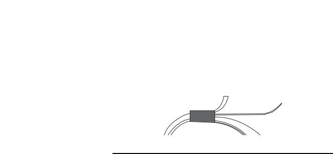
1.Strip about 7.6 cm (3 in.) of casing to expose the wires at each end of the cable.
2.Twist the drain wire and foil shield together and bend them away from the cable at the grounded end of the cable.
Grounded End
Twisted Foil Shield and Drain Wire
Black Wire
Casing
Shrink Wrap |
Clear Wire |
Ungrounded End
Black Wire
Casing |
Shrink Wrap |
Clear Wire |
Publication 1746-UM009B-EN-P - September 2007

Install and Wire the Modules |
19 |
|
|
3.Apply shrink wrap where wires leave the casing with the hot-air blower.
4.Cut off the drain wire and foil shield at the other end of the cable.
5.Apply shrink wrap to the junction where wires leave the casing.
6.Trim the signal wires to 5 cm (2 in.) lengths. Strip about 4.76 mm (3/16 in.) of insulation away to expose the copper strands for your connections.
7.Decide where you will connect the cable to earth ground, and ground it.
Refer to Ground the Cable on page 17.
8.Connect signal wires (black and clear) to the terminal block and to the input or output device.
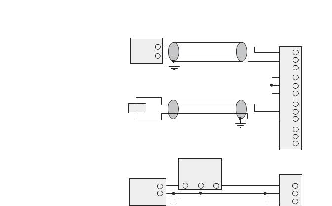
Wiring Diagram for Module, Sensor, and Load (showing differential inputs)
Important: Channels are not isolated from each other.
All analog commons are connected together internally.
+ |
|
|
|
Analog |
|
0 |
IN 0 + |
Sensor |
|
||
– |
|
1 |
IN 0 – |
|
2 |
ANL COM |
|
Earth |
|
||
Ground |
Important: Jumper |
3 |
IN 1 + |
|
|||
|
4 |
IN 1 – |
|
|
unused inputs. |
||
|
5 |
ANL COM |
|
|
|
||
Load |
|
6 |
not used |
|
7 |
OUT 0 |
|
|
|
||
|
Earth |
8 |
ANL COM |
|
9 |
not used |
|
|
Ground |
||
|
10 |
OUT 1 |
|
|
Important: Do not |
||
|
11 |
ANL COM |
|
|
jumper unused outputs. |
||
|
|
|
Publication 1746-UM009B-EN-P - September 2007

20 Install and Wire the Modules
|
Single-ended inputs are less immune to noise than are |
|
IMPORTANT |
||
differential inputs. |
||
|
||
|
||
|
|
Wiring Schematic for Single-ended Current-loop Analog Input Connections
Important: The module does not provide loop power for analog inputs. Use a power supply that matches the transmitter specifications.
2-wire Transmitter |
Transmitter |
|||
|
|
|||
|
+ |
+ |
– |
|
Power |
|
|
||
Supply |
– |
|
|
|
3-wire Transmitter |
Transmitter |
|||
Supply |
Signal |
|||
|
|
|||
|
+ |
|
GND |
|
Power |
|
|
||
Supply |
– |
|
|
|
4-wire Transmitter
|
|
Transmitter |
|
|
|
Supply |
Signal |
Power |
+ |
+ |
+ |
Supply |
– |
– |
– |
Module IN +
IN –
ANL COM
Module IN +
IN –
ANL COM
Module IN +
IN –
ANL COM
Minimize Ground Loops
9.Repeat steps 1…6 for each channel. For each unused input channel, jumper together the plus (+), minus (–), and common (ANL COM) terminals. For each unused output channel, do not connect terminals.
To keep the ground-loop currents of input circuits to a minimum, we recommend that you:
•use the same power supply to power both input channels of a module.
•otherwise, tie together the grounds of separate power supplies.
See Wiring Schematic for Single-ended Current-loop Analog Input Connections for more information.
Publication 1746-UM009B-EN-P - September 2007
|
|
Install and Wire the Modules 21 |
|
|
|
|
|
Label the Terminal Block |
The terminal block has a write-on label. Use it to ensure that you |
||
|
install the correct terminal block on the corresponding module. |
||
|
Terminal Block |
|
|
|
|
|
|
|
Note: The black dot on the label |
SLOT ____ RACK ____ |
|
|
MODULE _____ |
|
|
|
indicates the position of terminal 0. |
|
|
|
|
|
|
Publication 1746-UM009B-EN-P - September 2007

22 Install and Wire the Modules
Publication 1746-UM009B-EN-P - September 2007
Chapter 3
Click and Drag
Configuration
Access Files to Configure I/O
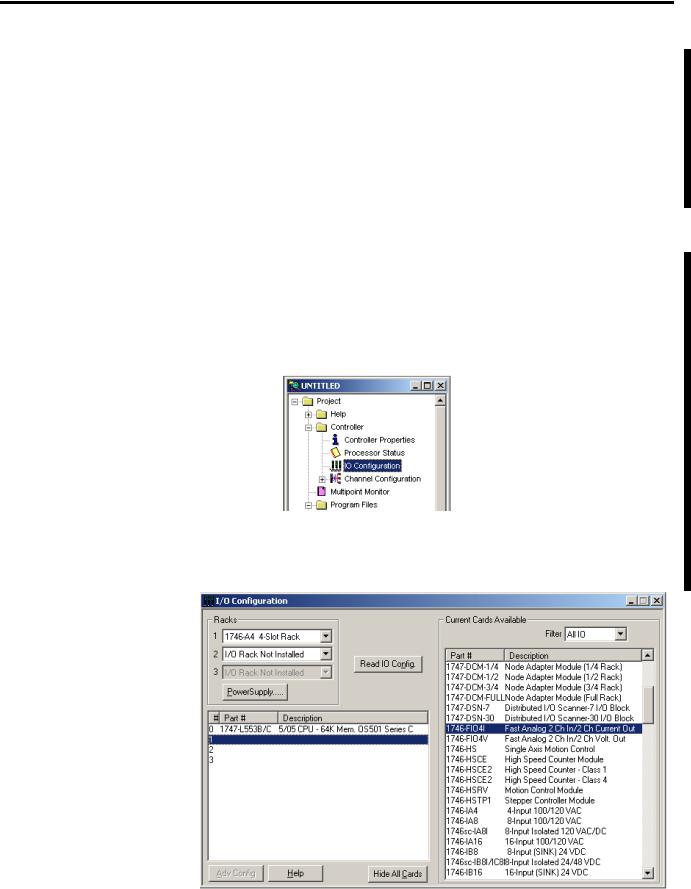
There are two ways to configure the SLC Chassis for a 1746-FIO4I/V module. You can either click and drag items from the list or you can use the Read IO Config method.
Follow these steps to configure the SLC chassis by clicking and dragging modules.
1.Double-click the menu item to open the IO Configuration menu in RSLogix500 software.
2.Place the 1746-FIO4I/V module into the correct slot by clicking and dragging from the list.
Publication 1746-UM009B-EN-P - September 2007
24 Access Files to Configure I/O
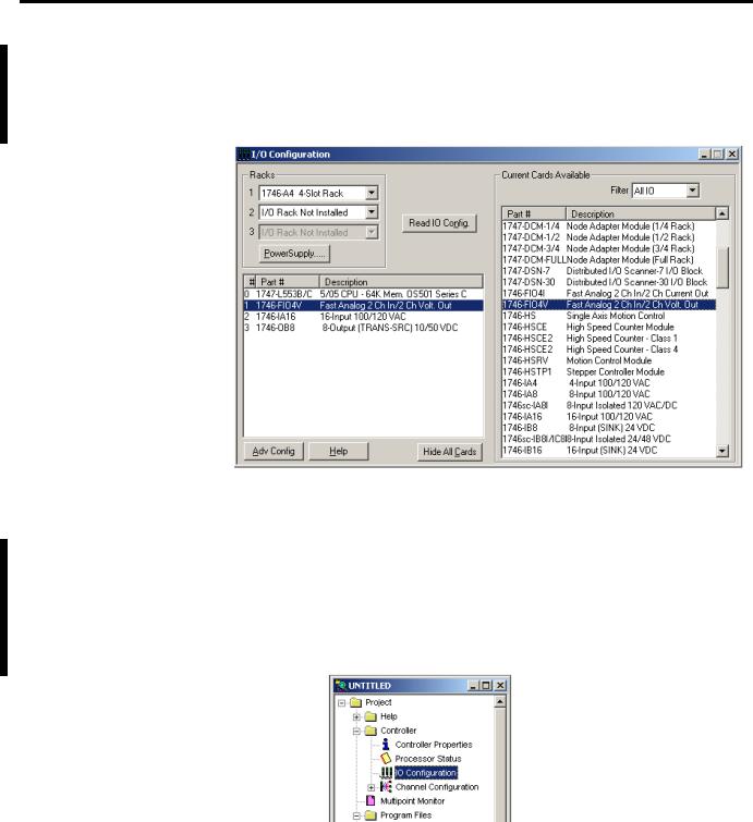
Read IO Config Method
The I/O Configuration is now complete. Each slot shows the corresponding module that is located on the rack. In this example the 1746-FIO4V is in slot 1.
Follow these steps to configure the SLC chassis by using the Read IO configuration method.
1.Double-click the menu item to open the IO Configuration menu in RSLogix500 software.
Publication 1746-UM009B-EN-P - September 2007

Access Files to Configure I/O |
25 |
|
|
2.Place the 1746-FIO4I/V module into the correct slot by clicking Read IO Config.
The following screen appears.
3.Select either the driver and processor node number or use the Who Active button to browse for the device.
•If you selected the driver and node number, proceed to step 5.
•If you clicked Who Active, the following screen appears.
Publication 1746-UM009B-EN-P - September 2007

26 Access Files to Configure I/O
The Who Active screen lets you browse for the SLC device.
4.Locate the SLC Chassis under the appropriate driver and click OK.
You are brought back to the Read IO Config screen.
5.Click Read IO Config and the rack is populated automatically.
Publication 1746-UM009B-EN-P - September 2007

Access Files to Configure I/O |
27 |
|
|
The I/O Configuration is now complete. Each slot shows the corresponding module on the rack. In this example the 1746-FIO4V is in slot 1.
Publication 1746-UM009B-EN-P - September 2007

28 Access Files to Configure I/O
Publication 1746-UM009B-EN-P - September 2007

Chapter 4
Processor and Module Considerations
This chapter describes concepts that you need to understand to program the fast analog I/O module in an SLC 500 system.
The following are processor considerations.
•Update processor analog I/O data
•Monitor analog I/O data
•Address I/O image words
The following are module considerations.
•Resolve data of the module’s I/O channel converters
•Convert analog input data
•Compute the analog input signal level
•Convert analog output data
•Compute the analog output
•Filter input channel
•Compute time delay for A/D conversion
•Determine response to slot disable
•Determine safe state for outputs
•Enter module ID code
Publication 1746-UM009B-EN-P - September 2007
Loading...