


Texas Instruments TPS60203DGSR, TPS60202DGSR, TPS60203DGS, TPS60202DGS, TPS60201DGSR Datasheet
...TPS60200, TPS60201, TPS60202, TPS60203 REGULATED 3.3 V, 100-mA LOW-RIPPLE CHARGE PUMP LOW POWER DC/DC CONVERTERS
SLVS274 ± MARCH 2000
features
DRegulated 3.3-V Output Voltage With up to 100 mA Output Current From a 1.8 V to 3.6 V Input Voltage
DLess Than 5 mV(PP) Output Voltage Ripple Achieved With Push-Pull Topology
DIntegrated Low-Battery and Power-Good Detector
DSwitching Frequency Can Be Synchronized to External Clock Signal
DExtends Battery Usage With up to 90% Efficiency and 35 A Quiescent Supply
Current
DReliable System Shutdown Because Output Capacitor Is Discharged When Device Is Disabled
DEasy-To-Design, Low Cost, Low EMI Power Supply Since No Inductors Are Used
D0.05 A Shutdown Current, Battery Is
Isolated From Load in Shutdown Mode
DCompact Converter Solution in Ultra-Small 10-pin MSOP With Only Four External Capacitors Required
DEvaluation Module Available (TPS60200EVM-145)
applications
DReplaces DC/DC Converters With Inductors in Battery Powered Applications Like:
±Two Battery Cells to 3.3-V Conversion
±MP3 Portable Audio Players
±Battery-Powered Microprocessor Systems
±Backup-Battery Boost Converters
±PDA's, Organizers, Cordless Phones
±Handheld Instrumentation
±Glucose Meters and Other Medical Instruments
´
description
The TPS6020x step-up, regulated charge pumps generate a 3.3-V ± 4% output voltage from a 1.8-V to 3.6-V input voltage. The devices are typically powered by two Alkaline, NiCd or NiMH battery cells and operate down to a minimum supply voltage of 1.6 V. Continuous output current is a minimum of 100 mA for the TPS60200 and TPS60201 and 50 mA for the TPS60202 and TPS60203, all from a 2-V input. Only four external capacitors are needed to build a complete low-ripple dc/dc converter. The push-pull operating mode of two single-ended charge pumps assures the low output voltage ripple as current is continuously transferred to the output.
INPUT |
|
|
|
|
|
|
|
OUTPUT |
|
|
|
TPS60200 |
|
|
||
|
|
|
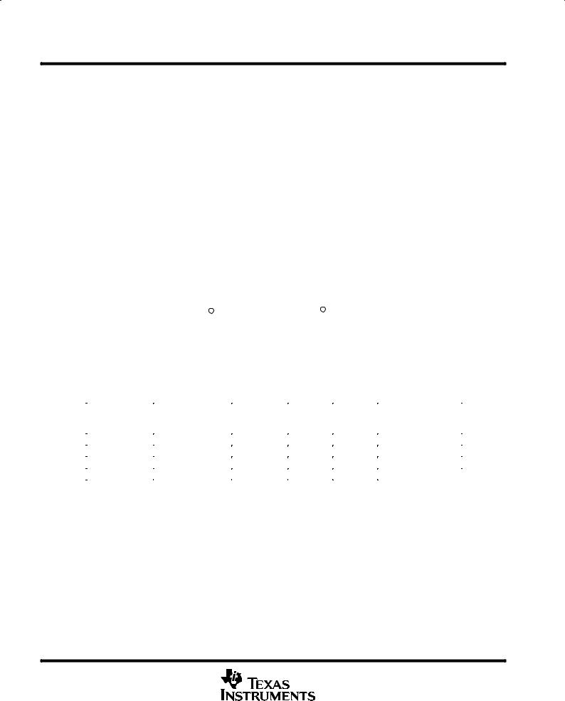
TPS60200 |
|
|
|
|
PEAK OUTPUT CURRENT |
|
|||||||
1.6V to 3.6V |
|
7 |
5 |
|
3.3V, 100 mA |
|
|
|||||||||
|
|
|
|
|
|
|
vs |
|
|
|||||||
|
IN |
OUT |
|
|
|
|
|
|
|
|
|
|||||
|
|
|
|
|
|
|
|
|
|
|
INPUT VOLTAGE |
|
|
|||
|
|
|
R1 |
|
|
|
|
C o |
|
|
350 |
|
|
|
||
C i |
|
|
|
|
R3 |
|
|
|
|
|
|
|
||||
|
|
|
|
2.2 |
F |
|
|
|
|
|
|
|||||
2.2 |
F |
|
1 |
LBI |
|
10 |
|
|
|
|
|
|
|
|
||
|
|
|
|
|
|
|
300 |
|
|
|
|
|
||||
|
|
|
|
|
LBO |
|
|
|
|
|
|
|
|
|
||
|
|
|
R2 |
|
|
|
|
|
mA± |
|
|
|
|
|
||
|
|
|
|
|
|
|
|
|
|
|
|
|
|
|||
|
|
|
|
|
|
|
|
|
|
|
|
|
|
|
||
|
|
|
|
|
|
|
Low Battery |
|
|
|
|
|
|
|||
|
|
|
|
|
|
|
|
|
|
|
|
|
|
|||
|
1 |
F |
3 |
C1± |
C2± |
8 |
C2 |
Warning |
|
Current |
250 |
|
|
|
|
|
|
|
|
|
|
|
|
|
|
||||||||
|
|
|
4 |
C1+ |
C2+ |
6 |
|
|
|
|
|
|
|
|
|
|
|
|
C1 |
|
|
|
|
|
|
|
Outout |
200 |
|
|
|
|
|
|
|
|
9 |
EN |
|
|
1 F |
|
|
150 |
|
|
|
|
|
|
|
|
|
|
|
|
|
|
|
|
|
|
|
||||
|
|
|
|
|
|
|
|
|
|
|
|
|
|
|
||
|
|
OFF/ON |
|
GND |
|
|
|
|
± |
|
|
|
|
|
|
|
|
|
|
|
|
|
|
|
100 |
|
|
|
|
|
|||
|
|
|
|
|
2 |
|
|
|
|
O |
|
|
|
|
|
|
|
|
|
|
|
|
|
|
|
I |
|
|
|
|
|
|
|
|
Figure 1. Typical Application Circuit |
|
|
50 |
|
|
|
|
|
|||||||
|
|
|
|
|
|
|
|
|
||||||||
|
|
|
With Low-Battery Warning |
|
|
|
0 |
|
|
|
|
|
||||
|
|
|
|
|
|
|
|
|
|
|
1.6 |
2.0 |
2.4 |
2.8 |
3.2 |
3.6 |
|
|
|
|
|
|
|
|
|
|
|
|
|
VI ± Input Voltage ± V |
|
|
|
Please be aware that an important notice concerning availability, standard warranty, and use in critical applications of Texas Instruments semiconductor products and disclaimers thereto appears at the end of this data sheet.
PRODUCTION DATA information is current as of publication date. Products conform to specifications per the terms of Texas Instruments standard warranty. Production processing does not necessarily include testing of all parameters.
Copyright 2000, Texas Instruments Incorporated
POST OFFICE BOX 655303 •DALLAS, TEXAS 75265 |
1 |
TPS60200, TPS60201, TPS60202, TPS60203
REGULATED 3.3 V, 100-mA LOW-RIPPLE CHARGE PUMP
LOW POWER DC/DC CONVERTERS
SLVS274 ± MARCH 2000
description (continued)
The devices operate in the newly developed LinSkip mode. In this operating mode, the device switches seamlessly from the power saving pulse-skip mode at light loads to the low-noise constant-frequency, linear-regulation mode once the output current exceeds the LinSkip threshold of about 7-mA. Even in pulse-skip mode the output ripple is maintained at a very low level because the output resistance of the charge pump is still regulated.
Three operating modes can be programmed using the EN pin. EN = low disables the device, shuts down all internal circuits and disconnects the output from the input. EN = high enables the device and programs it to run from the internal oscillator. The devices operate synchronized to an external clock signal if EN is clocked; thus switching harmonics can be controlled and minimized. The devices include a low-battery detector that issues a warning if the battery voltage drops below a user-defined threshold voltage or a power-good detector that goes active when the output voltage reaches about 90% of its nominal value.
Device options with either a low-battery or power good detector are available. This dc/dc converter requires no inductors therefore EMI of the system is reduced to a minimum. It is available in the small 10-pin MSOP package (DGS).
|
|
|
|
|
DGS PACKAGES |
|
|
|
|
||
|
|
TPS60200, |
|
|
|
|
TPS60201, |
|
|
||
|
|
TPS60202 |
|
|
|
|
TPS60203 |
|
|
||
|
|
|
|
|
|
GND |
|
|
|
|
PG |
LBI |
|
1 |
10 |
|
LBO |
|
1 |
10 |
|
||
|
|
|
|
||||||||
GND |
|
2 |
9 |
|
EN |
GND |
|
2 |
9 |
|
EN |
C1± |
|
3 |
8 |
|
C2± |
C1± |
|
3 |
8 |
|
C2± |
C1+ |
|
4 |
7 |
|
IN |
C1+ |
|
4 |
7 |
|
IN |
OUT |
|
5 |
6 |
|
C2+ |
OUT |
|
5 |
6 |
|
C2+ |
|
|
|
|
|
|
|
|
|
|
|
|
AVAILABLE OPTIONS
|
PART NUMBER² |
MARKING |
OUTPUT |
OUTPUT |
|
|
T |
DGS |
CURRENT |
VOLTAGE |
DEVICE FEATURES |
||
A |
|
PACKAGE |
(mA) |
(V) |
|
|
|
|
|
||||
|
|
|
|
|
|
|
|
TPS60200DGS |
AEX |
100 |
3.3 |
Low-battery detector |
|
|
|
|
|
|
|
|
±40°C to 85°C |
TPS60201DGS |
AEY |
100 |
3.3 |
Power-good detector |
|
|
|
|
|
|
||
TPS60202DGS |
AEZ |
50 |
3.3 |
Low-battery detector |
||
|
||||||
|
|
|
|
|
|
|
|
TPS60203DGS |
AFA |
50 |
3.3 |
Power-good detector |
²The DGS package is available taped and reeled. Add R suffix to device type (e.g. TPS60200DGSR) to order quantities of 3000 devices per reel.
2 |
POST OFFICE BOX 655303 •DALLAS, TEXAS 75265 |

TPS60200, TPS60201, TPS60202, TPS60203
REGULATED 3.3 V, 100-mA LOW-RIPPLE CHARGE PUMP
LOW POWER DC/DC CONVERTERS
SLVS274 ± MARCH 2000
functional block diagrams
TPS60200 and TPS60202 with low-battery detector
0° |
|
Charge Pump 1 |
|
|
IN |
|
|
Oscillator |
|
|
|
180° |
|
C1+ |
C1 |
|
|
||
|
|
|
|
|
|
C1± |
|
EN |
|
|
|
Control |
|
Charge Pump 2 |
|
|
C2+ |
|
|
Circuit |
|
|
|
_ |
|
C2± |
C2 |
+ |
|
|
|
|
|
|
|
VREF |
+ |
OUT |
|
± |
|
|
Shutdown/ |
_ |
Auto± |
|
|
|
Start-Up |
Discharge |
_ |
LBI |
||
+ |
|||||
Control |
|
+ |
|
||
|
|
|
|
||
|
+ |
0.8* VIN |
|
+ |
|
|
± |
VREF |
|||
|
|
|
± |
GND LBO
TPS60201 and TPS60203 with power-good detector
0° |
Charge Pump 1 |
|
IN |
|
|
Oscillator |
|
|
180° |
C1+ |
C1 |
|
||
|
|
|
|
C1± |
|
EN |
|
|
Control |
Charge Pump 2 |
|
C2+ |
|
|
Circuit |
|
|
_ |
C2± |
C2 |
|
|
|
+ |
|
|
VREF |
+ |
|
OUT |
|
± |
|
|
||
Shutdown/ |
_ |
Auto± |
|
|
Start-Up |
Discharge |
_ |
||
+ |
||||
Control |
|
+ |
||
|
|
|
||
|
+ |
0.8* VIN |
+ |
|
|
± |
|||
|
|
|
VREF ± |
|
|
|
GND |
PG |
POST OFFICE BOX 655303 •DALLAS, TEXAS 75265 |
3 |

TPS60200, TPS60201, TPS60202, TPS60203
REGULATED 3.3 V, 100-mA LOW-RIPPLE CHARGE PUMP
LOW POWER DC/DC CONVERTERS
SLVS274 ± MARCH 2000
|
|
|
Terminal Functions |
|
|
|
|
||
TERMINAL |
I/O |
DESCRIPTION |
||
NAME |
NO. |
|||
|
|
|||
|
|
|
|
|
C1+ |
4 |
|
Positive terminal of the flying capacitor C1 |
|
|
|
|
|
|
C1± |
3 |
|
Negative terminal of the flying capacitor C1 |
|
|
|
|
|
|
C2+ |
6 |
|
Positive terminal of the flying capacitor C2 |
|
|
|
|
|
|
C2± |
8 |
|
Negative terminal of the flying capacitor C2 |
|
|
|
|
|
|
|
|
|
Device-enable input. Three operating modes can be programmed with the EN pin. |
|
|
|
|
± EN = Low disables the device. Output and input are isolated in the shutdown mode and the output capacitor is |
|
EN |
9 |
I |
automatically discharged. |
|
± EN = High lets the device run from the internal oscillator. |
||||
|
|
|
||
|
|
|
± If an external clock signal is applied to the EN pin, the device is in Sync±Mode and runs synchronized at the |
|
|
|
|
frequency of the external clock signal. |
|
|
|
|
|
|
GND |
2 |
|
Ground |
|
|
|
|
|
|
IN |
7 |
I |
Supply input. Bypass IN to GND with a capacitor of the same size as Co. |
|
|
|
|
Low-battery detector input for TPS60200 and TPS60202. A low-battery warning is generated at the LBO pin when |
|
LBI/GND |
1 |
I |
the voltage on LBI drops below the threshold of 1.18 V. Connect LBI to GND if the low-battery detector function is |
|
|
|
|
not used. For the devices TPS60201 and TPS60203, this pin has to be connected to ground (GND pin). |
|
|
|
|
|
|
|
|
|
Open-drain low-battery detector output for TPS60200 and TPS60202. This pin is pulled low if the voltage on LBI |
|
|
|
|
drops below the threshold of 1.18 V. A pullup resistor should be connected between LBO and OUT or any other logic |
|
LBO/PG |
10 |
O |
supply rail that is lower than 3.6 V. |
|
Open-drain power-good detector output for TPS60201 and TPS60203. As soon as the voltage on OUT reaches |
||||
|
|
|
||
|
|
|
about 90% of it is nominal value this pin goes active high. A pullup resistor should be connected between PG and |
|
|
|
|
OUT or any other logic supply rail that is lower than 3.6 V. |
|
|
|
|
|
|
OUT |
5 |
O |
Regulated 3.3-V power output. Bypass OUT to GND with the output filter capacitor Co. |
|
detailed description
operating principle
The TPS6020x charge pumps provide a regulated 3.3 V output from a 1.8 V to 3.6 V input. They deliver up to 100 mA load current while maintaining the output at 3.3 V ± 4%. Designed specifically for space critical battery powered applications, the complete converter requires only four external capacitors. The device is using the push-pull topology to achieve lowest output voltage ripple. The converter is also optimized for smallest board space. It makes use of small sized capacitors, with the highest output current rating per output capacitance and package size.
The TPS6020x circuits consist of an oscillator, a 1.18 V voltage reference, an internal resistive feedback circuit, an error amplifier, two charge pump power stages with high current MOSFET switches, a shutdown/start-up circuit, a control circuit, and an auto-discharge transistor (see functional block diagrams).
push-pull operating mode
The two single-ended charge pump power stages operate in the so-called push-pull operating mode, i.e. they operate with a 180°C phase shift. Each single-ended charge pump transfers charge into its transfer capacitor (C1 or C2) in one half of the period. During the other half of the period (transfer phase), the transfer capacitor is placed in series with the input to transfer its charge to Co. While one single-ended charge pump is in the charge phase, the other one is in the transfer phase. This operation assures an almost constant output current which ensures a low output ripple.
If the clock were to run continuously, this process would eventually generate an output voltage equal to two times the input voltage (hence the name voltage doubler). In order to provide a regulated fixed output voltage of 3.3 V, the TPS6020x devices use either pulse-skip or constant-frequency linear-regulation control mode. The mode is automatically selected based on the output current. If the load current is below the LinSkip current threshold, it switches into the power-saving pulse-skip mode to boost efficiency at low output power.
4 |
POST OFFICE BOX 655303 •DALLAS, TEXAS 75265 |

TPS60200, TPS60201, TPS60202, TPS60203
REGULATED 3.3 V, 100-mA LOW-RIPPLE CHARGE PUMP
LOW POWER DC/DC CONVERTERS
SLVS274 ± MARCH 2000
detailed description (continued)
constant-frequency mode
When the output current is higher then the LinSkip current threshold, the charge pump runs continuously at the
switching frequency f(OSC). The control circuit, fed from the error amplifier, controls the charge on C1 and C2 by controlling the gates and hence the rDS(ON) of the integrated MOSFETs. When the output voltage decreases, the gate drive increases, resulting in a larger voltage across C1 and C2. This regulation scheme minimizes
output ripple. Since the device switches continuously, the output signal contains well-defined frequency components, and the circuit requires smaller external capacitors for a given output ripple. However, constant-frequency mode, due to higher operating current, is less efficient at light loads. For this reason, the device switches seamlessly into the pulse-skip mode when the output current drops below the LinSkip current threshold.
pulse-skip mode
The regulator enters the pulse-skip mode when the output current is lower than the LinSkip current threshold of 7 mA. In the pulse-skip mode, the error amplifier disables switching of the power stages when it detects an output voltage higher than 3.3 V. The controller skips switching cycles until the output voltage drops below 3.3 V. Then the error amplifier reactivates the oscillator and switching of the power stages starts again. A 30 mV output voltage offset is introduced in this mode.
The pulse-skip regulation mode minimizes operating current because it does not switch continuously and deactivates all functions except the voltage reference and error amplifier when the output is higher than 3.3 V.
Even in pulse-skip mode the rDS(ON) of the MOSFETs is controlled. This way the energy per switching cycle that is transferred by the charge pump from the input to the output is limited to the minimum that is necessary to
sustain a regulated output voltage, with the benefit that the output ripple is kept to a minimum. When switching is disabled from the error amplifier, the load is also isolated from the input.
start up, shutdown, and auto-discharge
During start-up, i.e. when EN is set from logic low to logic high, the output capacitor is directly connected to IN and charged up with a limited current until the output voltage VO reaches 0.8 ×VI. When the start-up comparator detects this limit, the converter begins switching. This precharging of the output capacitor guarantees a short start-up time. In addition, the inrush current into an empty output capacitor is limited. The converter can start into a full load, which is defined by a 33-Ω or 66-Ω resistor, respectively.
Driving EN low disables the converter. This disables all internal circuits and reduces the supply current to only 0.05 µA. The device exits shutdown once EN is set high. When the device is disabled, the load is isolated from the input. This is an important feature in battery operated products because it extends the products shelf life.
Additionally, the output capacitor will automatically be discharged after EN is taken low. This ensures that the system, when switched off, is in a stable and reliable condition since the supply voltage is removed from the supply pins.
synchronization to an external clock signal
The operating frequency of the charge pump is limited to 400 kHz in order to avoid interference in the sensitive 455 kHz IF band. The device can either run from the integrated oscillator, or an external clock signal can be used to drive the charge pump. The maximum frequency of the external clock signal is 800 kHz. The switching frequency used internally to drive the charge pump power stages is half of the external clock frequency. The external clock signal is applied to the EN-pin. The device will switch off if the signal on EN is hold low for more than 10 µs.
When the load current drops below the LinSkip current threshold, the devices will enter the pulse-skip mode but stay synchronized to the external clock signal.
POST OFFICE BOX 655303 •DALLAS, TEXAS 75265 |
5 |

TPS60200, TPS60201, TPS60202, TPS60203
REGULATED 3.3 V, 100-mA LOW-RIPPLE CHARGE PUMP
LOW POWER DC/DC CONVERTERS
SLVS274 ± MARCH 2000
detailed description (continued)
low-battery detector (TPS60200 and TPS60202)
The low-battery comparator trips at 1.18 V ± 4% when the voltage on pin LBI ramps down. The voltage V(TRIP) at which the low-battery warning is issued can be adjusted with a resistive divider as shown in Figure 2. The
sum of resistors R1 and R2 is recommended to be in the 100 kΩ to 1 MΩ range. When choosing R1 and R2, be aware of the input leakage current into the LBI pin.
LBO is an open drain output. An external pullup resistor to OUT, or any other voltage rail in the appropriate range, in the 100 kΩ to 1 MΩ range is recommended. During start-up, the LBO output signal is invalid for the first 500 µs. LBO is high impedance when the device is disabled. If the low-battery comparator function is not used, connect LBI to ground and leave LBO unconnected. The low-battery detector is disabled when the device is switched off.
VO
IN
VBAT
R3
|
|
|
R1 |
LBO |
|
LBI |
R1 |
_ |
V(TRIP) + 1.18 V 1 ) R2 |
||
|
+ |
|
R2 |
|
VREF |
+ |
|
|
± |
|
Figure 2. Programming of the Low-Battery Comparator Trip Voltage
A 100 nF ceramic capacitor should be connected in parallel to R2 if large line transients are expected. These voltage drops can inadvertently trigger the low-battery comparator and produce a wrong low-battery warning signal at the LBO pin.
Formulas to calculate the resistive divider for low-battery detection, with VLBI = 1.13 V to 1.23 V and the sum of resistors R1 and R2 equal 1 MΩ:
R2 + 1 MW |
VLBI |
(1) |
|||||
VBat |
|
|
|
||||
R1 + 1 MW * R2 |
|
|
|
|
|
(2) |
|
Formulas to calculate the minimum and maximum battery voltage: |
|
||||||
VBat(min) + VLBI(min) |
R1(min) ) R2(max) |
|
(3) |
||||
|
|
R2(max) |
|||||
|
|
|
|
|
|||
VBat(max) + VLBI(max) |
R1(max) ) R2(min) |
(4) |
|||||
|
|
R2(min) |
|
||||
|
|
|
|
|
|||
6 |
POST OFFICE BOX 655303 •DALLAS, TEXAS 75265 |
 Loading...