


 Loading...
Altivar 61/71
Modbus TCP/IP
Daisy Chain Ethernet card
User manual
VW3 A3 310d |
11/2009 |
AAV69931
www.schneider-electric.com

Table of contents
Important Information _________________________________________________________________________________________ 5
Before you begin_____________________________________________________________________________________________ 6
Documentation structure_______________________________________________________________________________________ 7
Introduction_________________________________________________________________________________________________ 8 Presentation _____________________________________________________________________________________________ 8 Notation ________________________________________________________________________________________________ 8
Hardware setup _____________________________________________________________________________________________ 9 Receipt _________________________________________________________________________________________________ 9 Hardware description ______________________________________________________________________________________ 9 Installing the card in the drive________________________________________________________________________________ 9
Connecting to the Ethernet network _____________________________________________________________________________ 10 Card RJ45 connector pinout ________________________________________________________________________________ 10 Example of connection to an Ethernet network _________________________________________________________________ 10 Ethernet network connection elements________________________________________________________________________ 11
Ethernet menu _____________________________________________________________________________________________ 12 Access to Ethernet menu via graphic display terminal ____________________________________________________________ 12 Access to Ethernet menu via the integrated display terminal _______________________________________________________ 12 Ethernet menu parameters _________________________________________________________________________________ 13
Configuration ______________________________________________________________________________________________ 16 List of functions to be configured ____________________________________________________________________________ 16 Configuring IP addresses __________________________________________________________________________________ 17 Reserving control ________________________________________________________________________________________ 19 Configuring IO Scanning___________________________________________________________________________________ 19 Configuring the control ____________________________________________________________________________________ 20 Configuring the fault management ___________________________________________________________________________ 23 Configuring monitored parameters ___________________________________________________________________________ 25
Diagnostics ________________________________________________________________________________________________ 26 Signalling LEDs _________________________________________________________________________________________ 26 Available information _____________________________________________________________________________________ 27 Monitoring the control _____________________________________________________________________________________ 27 Troubleshooting the communication fault ______________________________________________________________________ 28 Troubleshooting the card fault ______________________________________________________________________________ 29
Software setup _____________________________________________________________________________________________ 30 List of services supported __________________________________________________________________________________ 30 TCP connections ________________________________________________________________________________________ 30
Modbus TCP server _________________________________________________________________________________________ 31 Modbus TCP frames______________________________________________________________________________________ 31 Drive Modbus servers_____________________________________________________________________________________ 31 Ethernet card parameters__________________________________________________________________________________ 32 List of Modbus functions supported __________________________________________________________________________ 35 “Read Holding Registers” (3) function ________________________________________________________________________ 35 “Write Single Register” (6) function___________________________________________________________________________ 36 “Write Multiple Registers” (16 = 16#10) function ________________________________________________________________ 37 “Read/Write Multiple Registers” (23 = 16#17) function____________________________________________________________ 38 “Read Device Identification” (43 = 16#2B) function ______________________________________________________________ 39
IO Scanning service _________________________________________________________________________________________ 40 Presentation ____________________________________________________________________________________________ 40 Periodic variables ________________________________________________________________________________________ 40 Address table ___________________________________________________________________________________________ 41
FDR service _______________________________________________________________________________________________ 42 Presentation ____________________________________________________________________________________________ 42 Local configuration _______________________________________________________________________________________ 43 Downloaded configuration _________________________________________________________________________________ 44 Periodic saving __________________________________________________________________________________________ 46 Other commands ________________________________________________________________________________________ 46 Configuration file_________________________________________________________________________________________ 46
AAV69931 11/2009 |
3 |

Table of contents
Standard Web server ________________________________________________________________________________________ 47 Web server functions _____________________________________________________________________________________ 47 Applets ________________________________________________________________________________________________ 48 Access to the Web server__________________________________________________________________________________ 49 Web server user interface__________________________________________________________________________________ 50 “Home” menu ___________________________________________________________________________________________ 50 “Monitoring” menu________________________________________________________________________________________ 50 “Altivar Viewer” page _____________________________________________________________________________________ 51 “Data Viewer” page_______________________________________________________________________________________ 52 “Altivar Chart” page_______________________________________________________________________________________ 53 “Diagnostics” menu_______________________________________________________________________________________ 53 “Ethernet Statistics” page __________________________________________________________________________________ 54 “Setup” menu ___________________________________________________________________________________________ 54 “HTTP password” and “Data write password pages” _____________________________________________________________ 55 “FDR Agent” page________________________________________________________________________________________ 56 “IO Scanner” page _______________________________________________________________________________________ 58 "Email" page ____________________________________________________________________________________________ 61 “Documentation” menu ____________________________________________________________________________________ 62
FTP server ________________________________________________________________________________________________ 63
Downloading from the Web server ______________________________________________________________________________ 65
SNMP agent _______________________________________________________________________________________________ 68
Setup using PL7 ____________________________________________________________________________________________ 70
Setup using Concept ________________________________________________________________________________________ 76
Setup using ProWORX NxT ___________________________________________________________________________________ 77
4 |
AAV69931 11/2009 |
1. Important Information
NOTICE
Read these instructions carefully, and look at the equipment to become familiar with the device before trying to install, operate, or maintain it. The following special messages may appear throughout this documentation or on the equipment to warn of potential hazards or to call attention to information that clarifies or simplifies a procedure.
The addition of this symbol to a Danger or Warning safety label indicates that an electrical hazard exists, which will result in personnal injury if the instruction are not followed.
This is the safety alert symbol. It is used to alert you to potential personal injury hazards. Obey all safety messages that follow this symbol to avoid possible injury or death.
 DANGER
DANGER indicates an imminently hazardous situation, which, if not avoided, will result in death, serious injury, or equipment damage.
 WARNING
Warning indicates a potentially hazardous situation, which, if not avoided, can result in death, serious injury, or equipment damage.
 CAUTION
CAUTION indicates a potentially hazardous situation, which, if not avoided, can result in injury or equipment damage.
PLEASE NOTE
Electrical equipment should be serviced only by qualified personnel. No responsibility is assumed by Schneider Electric for any consequences arising out of the use of this material. This document is not intended as an instruction manual for untrained persons.
© 2006 Schneider Electric. All Rights Reserved.
5 |
AAV69931 11/2009 |

2. Before you begin
Read and understand these instructions before performing any procedure with this drive.
 DANGER
HAZARDOUS VOLTAGE
•Read and understand this bulletin in its entirety before installing or operating Altivar 61 / 71 drive. This equipment must only be installed, adjusted, repaired, and maintained by qualified personnel.
•The user is responsible for compliance with all international and national electrical standards in force concerning protective grounding of all equipment.
•Many parts of this variable speed drive, including the printed circuit boards, operate at the line voltage. DO NOT TOUCH. Use only electrically insulated tools.
•DO NOT touch unshielded components or terminal strip screw connections with voltage present.
•DO NOT short across terminals PA and PC or across the DC bus capacitors.
•Install and close all the covers before applying power or starting and stopping the drive.
•Before servicing the variable speed drive
-Disconnect all power.
-Place a “DO NOT TURN ON” label on the variable speed drive disconnect.
-Lock the disconnect in the open position.
•Disconnect all power including external control power that may be present before servicing the drive.
WAIT 15 MINUTES to allow the DC bus capacitors to discharge. Then follow the DC bus voltage measurement procedure given in the Installation Manual to verify that the DC voltage is less than 45 VDC. The drive LEDs are not accurate indicators of the absence of DC bus voltage.
Failure to follow these instructions will result in death or serious injury.
 WARNING
DAMAGED EQUIPMENT
Do not install or operate any drive or drive accessory that appears damaged.The relays, inputs, or outputs of a damaged drive may not operate in a normal manner, leading to unintended equipment operation.
Failure to follow this instruction can result in death, serious injury, or equipment damage.
 WARNING
LOSS OF CONTROL
•The designer of any control scheme must consider the potential failure modes of control paths and, for certain critical control functions, provide a means to achieve a safe state during and after a path failure. Examples of critical control functions are emergency stop and overtravel stop.
•Separate or redundant control paths must be provided for critical control functions.
•System control paths may include communication links. Consideration must be given to the implications of unanticipated transmission delays or failures of the link.*
•Each implementation of an Altivar 71 Modbus TCP/IP Ethernet card must be individually and thoroughly tested for proper operation before being placed into service.
Failure to follow this instruction can result in death, serious injury, or equipment damage.
* For additional information, refer to NEMA ICS 1.1 (latest edition), "Safety Guidelines for the Application, Installation, and Maintenance of Solid State Control" and to NEMA ICS 7.1 (latest edition), "Safety Standards for Construction and Guide for Selection, Installation and Operation of Adjustable-Speed Drive Systems".
AAV69931 11/2009 |
6 |

3. Documentation structure
The following Altivar 61 / 71 technical documents are available on the Web site www.schneider-electric.com and on the CDROM delivered with each drive.
b Installation Manual
This manual describes:
•How to assemble the drive.
•How to connect the drive.
b Programming Manual
This manual describes:
•The functions.
•The parameters.
•How to use the drive display terminal (integrated display terminal and graphic display terminal).
b Communication Parameters Manual
This manual describes:
•The drive parameters with specific information (addresses, formats, etc.) for use via a bus or communication network.
•The operating modes specific to communication (state chart).
•The interaction between communication and local control.
b Modbus, CANopen, Ethernet, Profibus, INTERBUS, Uni-Telway, DeviceNet, Modbus Plus, Fipio, etc., manuals.
These manuals describe:
•Connection to the bus or network.
•Configuration of the communication-specific parameters via the integrated display terminal or the graphic display terminal.
•Diagnostics.
•Software setup.
•The communication services specific to the protocol.
b Altivar 58/58F Migration Manual
This manual describes the differences between the Altivar 71 and the Altivar 58/58F.
It explains how to replace an Altivar 58 or 58F, including how to replace drives communicating on a bus or network.
7 |
AAV69931 11/2009 |

4. Introduction
4. 1. Presentation
The Ethernet card (catalog number VW3 A3 310d) is used to connect an Altivar 61 / 71 drive to an Ethernet network using the Modbus TCP/IP protocol and Transparent Ready services.
The VW3 A3 310d card is equipped with two shielded RJ45 Ethernet connector.
The accessories for connection to the Ethernet network must be ordered separately.
The data exchanges permit full drive functionality:
•Configuration
•Adjustment
•Control
•Monitoring
•Diagnostics
The standard Web server (English only) provides access to the following pages:
•Altivar Viewer
•Data Viewer
•Ethernet
•Security
Etc.
The standard Web server can be adapted or replaced by a customized server depending on the requirements of the application.
The graphic display terminal or the integrated display terminal can be used to access numerous functions for communication diagnostics.
4. 2. Notation
Drive terminal displays
The graphic display terminal menus are shown in square brackets.
Example: [1.9 COMMUNICATION].
The integrated 7-segment display terminal menus are shown in round brackets.
Example: (COM-).
The parameter names displayed on the graphic display terminal are shown in square brackets.
Example: [Fallback speed].
The parameter codes displayed on the integrated 7-segment display terminal are shown in round brackets. Example: (LFF).
Formats
Hexadecimal values are written as follows: 16#
Binary values are written as follows: 2#
AAV69931 11/2009 |
8 |

5. Hardware setup
5. 1. Receipt
•Check that the card catalog number marked on the label is the same as that on the delivery note corresponding to the purchase order.
•Remove the option card from its packaging and check that it has not been damaged in transit.
 CAUTION
STATIC SENSITIVE COMPONENTS
The Modbus TCP/IP Ethernet card can be damaged by static electricity. Observe electrostatic precautions when handling and installing the card.
Failure to follow this instruction can result in equipment damage.
5. 2. Hardware description
LEDs
Shielded female RJ45 |
|
|
|
Shielded female RJ45 |
|
|
|
||
Ethernet connector |
|
|
|
Ethernet connector |
(Port 2) |
|
|
|
(Port 1) |
|
|
MAC address label |
||
|
|
on the Ethernet card |
||
5. 3. Installing the card in the drive
See the Installation Manual.
9 |
AAV69931 11/2009 |
6. Connecting to the Ethernet network
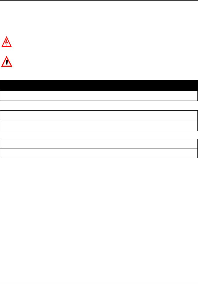
6. 1. Card RJ45 connector pinout
The Ethernet card is equipped with a shielded RJ45 connector. The shielding is connected to the drive ground. Use an STP (shielded twisted pair) Ethernet cable.
|
Pin |
Signal |
|
1 |
TD+ |
|
2 |
TD- |
|
3 |
RD+ |
|
4 |
|
|
5 |
|
|
6 |
RD- |
8........................1 |
7 |
|
8 |
|
|
|
|
The transmission speed is detected automatically by the card (10 Mbps or 100 Mbps).
The card can operate in half duplex or full duplex mode, whether connected to a hub or a switch and regardless of the transmission speed (10 Mbps or 100 Mbps).
The card supports the ETHERNET 2 frame format (IEEE 802-3 not supported).
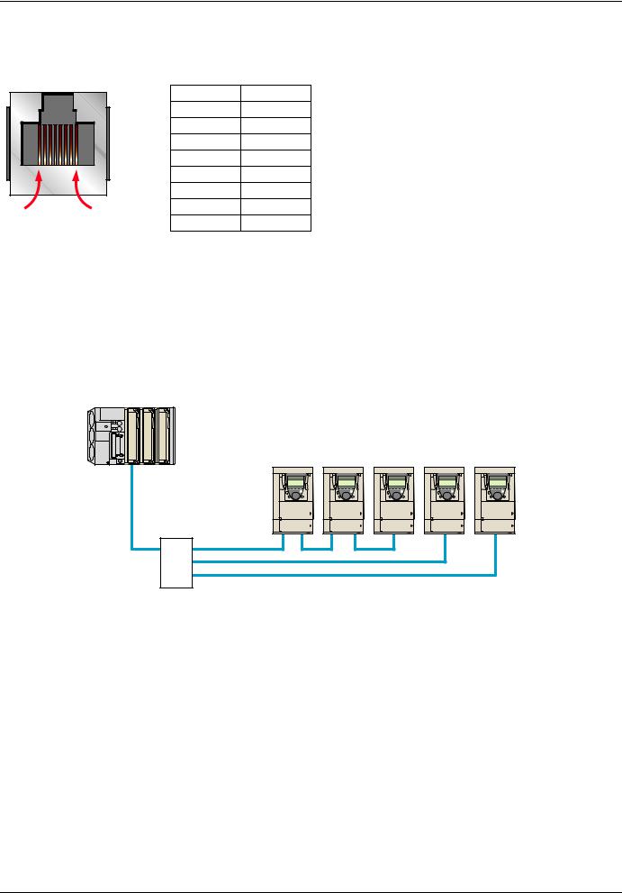
6. 2. Example of connection to an Ethernet network
PLC
Daisy chain and/or star topology (1)
ATV61/71 ATV61/71 ATV61/71 ATV61/71 ATV61/71
Ethernet switch
(1)When the topology is a daisy chain, if one drive is turned off, the other drive(s) trip in CNF fault
AAV69931 11/2009 |
10 |
6. Connecting to the Ethernet network
6. 3. Ethernet network connection elements
Please consult our catalog “Ethernet TCP/IP and the Web” (available on the Web site www.schneider-electric.com).
Connecting cables
Description |
Use |
|
Length |
Catalog number |
|
|
From |
To |
m |
|
|
Straight shielded twisted pair cables |
ATV71 |
Hubs |
2 |
490 NTW 000 02 |
|
2 RJ45 connectors |
(+ VW3 A3 310d card) |
499 NpH 1pp 10 |
|
|
|
5 |
490 NTW 000 05 |
||||
|
|
Switches |
|||
|
|
12 |
490 NTW 000 12 |
||
|
|
499 NpS 171 00 |
|||
|
|
|
40 |
490 NTW 000 40 |
|
|
|
|
80 |
490 NTW 000 80 |
Hubs and switches
Description |
Characteristics |
Catalog number |
|
Hubs |
4 × 10BASE-T ports |
499 NEH 104 10 |
|
|
4 |
× 100BASE-TX ports |
499 NEH 141 10 |
|
3 |
× 10BASE-T ports |
499 NOH 105 10 |
|
2 |
× 10BASE-FL ports, multimode fiber, ST (BFOC) connectors |
|
|
|
|
|
Switches |
5 × 10BASE-T/100BASE-TX ports |
499 NES 251 00 |
|
|
Unmanageable basic |
|
|
|
4 |
× 10BASE-T/100BASE-TX ports |
499 NMS 251 01 |
|
1 |
× 100BASE-FX port, multimode fiber, SC connectors |
|
|
Unmanageable |
|
|
|
3 |
× 10BASE-T/100BASE-TX ports |
499 NMS 251 02 |
|
2 |
× 100BASE-FX port, multimode fiber, SC connectors |
|
|
Unmanageable |
|
|
|
4 |
× 10BASE-T/100BASE-TX ports |
499 NSS 251 01 |
|
1 |
× 100BASE-FX port, monomode fiber, SC connectors |
|
|
Unmanageable |
|
|
|
3 |
× 10BASE-T/100BASE-TX ports |
499 NSS 251 02 |
|
2 |
× 100BASE-FX port, monomode fiber, SC connectors |
|
|
Unmanageable |
|
|
|
8 |
× 10BASE-T/100BASE-TX ports |
499 NES 181 00 |
|
Unmanageable |
|
|
|
7 |
× 10BASE-T/100BASE-TX ports |
499 NES 271 00 |
|
Manageable |
|
|
|
5 |
× 10BASE-T/100BASE-TX ports |
499 NOS 271 00 |
|
2 |
× 100BASE-FX port, multimode fiber, SC connectors |
|
|
Manageable |
|
|
|
|
|
|
|
5 |
× 10BASE-T/100BASE-TX ports |
499 NSS 271 00 |
|
2 |
× 100BASE-FX port, monomode fiber, SC connectors |
|
Manageable
11 |
AAV69931 11/2009 |
7. Ethernet menu
7. 1. Access to Ethernet menu via graphic display terminal
The [ETHERNET] submenu is used to configure and display the Ethernet card parameters and can be accessed via the [1.9 - COMMUNICATION] menu.
If you are using the FDR (Faulty Device Replacement) function, you must also configure the device name in the [7. DISPLAY CONFIG.] menu, [7.1 USER PARAMETERS] submenu, [DEVICE NAME] submenu.
This menu is only accessible in expert mode: In the [2 ACCESS LEVEL] (LAC-) menu, set the level to [expert] (EPr).
RDY |
NET +0.00 Hz 0A |
|
1 DRIVE MENU |
1.1SIMPLY START
1.2MONITORING
1.3SETTINGS
|
|
|
|
|
1.4 MOTOR CONTROL |
|
|
|
RUN |
NET |
+50.00 Hz |
80A |
||
|
|
|
|
|
1.5 INPUTS/OUTPUTS CFG |
|
|
|
|
1.9 COMMUNICATION |
|
|||
|
|
|
|
|
Code |
<< |
>> |
Quick |
|
|
COM. SCANNER OUTPUT |
|
||
|
|
|
|
|
1.6 COMMAND |
|
|
|
|
MODBUS HMI |
|
|
||
RDY |
NET +0.00 Hz |
0A |
|
|
1.7 APPLICATION FUNCT. |
|
|
|
MODBUS NETWORK |
|
||||
|
MAIN MENU |
|
ENT |
|
1.8 FAULT MANAGEMENT |
|
ENT |
|
CANopen |
|
|
|||
1 DRIVE MENU |
|
|
|
1.9 COMMUNICATION |
|
|
|
ETHERNET |
|
|
||||
|
|
|
|
|
|
|
||||||||
2 ACCESS LEVEL |
|
|
|
1.10 DIAGNOSTICS |
|
|
|
|
Code |
<< |
>> |
Quick |
||
3 OPEN / SAVE AS |
|
|
|
1.11 IDENTIFICATION |
|
|
|
|
|
|
|
|
||
4 PASSWORD |
|
|
|
1.12 FACTORY SETTINGS |
|
|
|
|
|
|
|
|||
5 LANGUAGE |
|
|
|
1.13 USER MENU |
|
|
|
|
|
|
|
|
||
Code |
|
Quick |
|
|
1.14 PROGRAMMABLE CARD |
|
|
|
|
|
|
|
||
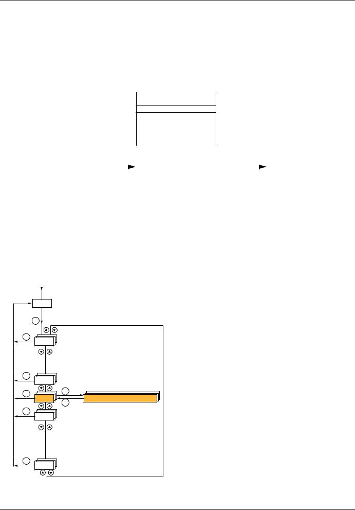
7. 2. Access to Ethernet menu via the integrated display terminal
The (EtH-) submenu is used to configure and display the Ethernet card parameters. It can be accessed via the (COM-) menu.
Note: The device name required for the FDR (Faulty Device Replacement) function cannot be configured via the integrated display terminal.
Power-up
XXX Displays the drive state
|
ENT |
|
|
ESC |
|
|
SIM- |
|
|
ESC |
|
|
FLt- |
|
|
ESC |
ENT |
|
EtH- |
|
|
CON- |
|
|
|
ESC |
|
ESC |
|
|
FCS- |
|
|
ESC |
|
|
LAC- |
|
AAV69931 |
11/2009 |
12 |

7. Ethernet menu
7. 3. Ethernet menu parameters
|
|
Code |
|
Description |
|
|
|
|
|
|
|
(bdr) |
|
|
M [Bit rate] |
|
|
|
|
|
|
|
|
|
Transmission speed detected on the network by the Ethernet card |
|
|
||
|
|
|
|
|
Type: |
|
Display (read-only) |
|
|
|
|
|
|
|
Possible |
|
[0 Mbps] (0M): Indeterminate speed (before automatic detection of the Ethernet network speed) |
|
|
|
|
|
|
|
values: |
|
[10 Mbps] (10M): 10 Mbps |
|
|
|
|
|
|
|
|
|
[100 Mbps] (100M): 100 Mbps |
|
|
|
|
|
|
|
Default value: |
|
[0 Mbps] (0M) |
|
|
|
|
(PAn-) |
|
b [DEVICE NAME] |
|
|
|||
|
|
|
|
|
Device name used by FDR service. Accessible with an ATV71 from V1.2 and a ATV61 from V1.3 version. |
|
|
||
|
|
|
|
|
Use the navigation selector button to increment the character (alphabetical order) and << and >> (F2 and F3) to switch |
|
|
||
|
|
|
|
|
to the next or previous character respectively. Use F1 to change to ABC, abc, 123, *[-. |
|
|
||
|
|
|
|
|
Type: |
|
Configuration (read and write) |
|
|
|
|
|
|
|
|
|
Display (read-only) |
|
|
|
|
|
|
|
Possible values: |
|
16 characters on 1 or 2 lines. |
|
|
|
|
|
|
|
Default value: |
[0] |
|
|
|
|
|
(IPC-) |
|
b [IP card] |
|
|
|||
|
|
(IPC1) |
|
|
M [139.160.069.241] (139) (160) (069) (241) |
|
|
||
|
|
(IPC2) |
|
|
Ethernet card IP address |
|
|
||
|
|
(IPC3) |
|
|
Type: |
|
Configuration (read and write) |
|
|
|
|
(IPC4) |
|
|
|
|
|
||
|
|
|
|
|
|
Display (read-only) if the address has been supplied by a BOOTP or DHCP server |
|
|
|
|
|
|
|
|
|
|
|
|
|
|
|
|
|
|
Possible |
|
• 0 to 255 for each of fields IPC1, IPC2, IPC3 and IPC4. |
|
|
|
|
|
|
|
values: |
|
• If the value is [0.0.0.0] (0) (0) (0) (0), the Ethernet card waits for an address from a BOOTP |
|
|
|
|
|
|
|
|
|
or DHCP server. |
|
|
|
|
|
|
|
|
|
Note: If you enter a value other than [0.0.0.0] (0) (0) (0) (0), dynamic addressing by a BOOTP |
|
|
|
|
|
|
|
|
|
or DHCP server is disabled. |
|
|
|
|
|
|
|
|
|
Note: After dynamic addressing by a BOOTP or DHCP server, the value [0.0.0.0] (0) (0) (0) (0) |
|
|
|
|
|
|
|
|
|
is replaced by the address supplied. |
|
|
|
|
|
|
|
Default value: |
[0.0.0.0] (0) (0) (0) (0) |
|
|
|
|
|
(IPM-) |
|
b [IP Mask] |
|
|
|||
|
|
(IPM1) |
|
|
M [255.255.254.0] (255) (255) (254) (0) |
|
|
||
|
|
(IPM2) |
|
|
Subnet mask |
|
|
|
|
|
|
(IPM3) |
|
|
Type: |
|
Configuration (read and write) |
|
|
|
|
(IPM4) |
|
|
|
|
|
||
|
|
|
|
|
|
Display (read-only) if the address has been supplied by a BOOTP or DHCP server |
|
|
|
|
|
|
|
|
|
|
|
|
|
|
|
|
|
|
Possible |
|
• 0 to 255 for each of fields IPM1, IPM2, IPM3 and IPM4. |
|
|
|
|
|
|
|
values: |
|
• If the value of the IP address [IP card] is [0.0.0.0] (0) (0) (0) (0), the Ethernet card waits for |
|
|
|
|
|
|
|
|
|
a mask from a BOOTP or DHCP server. |
|
|
|
|
|
|
|
|
|
Note: After dynamic addressing by a BOOTP or DHCP server, the current value is replaced by the |
|
|
|
|
|
|
|
|
|
address supplied. |
|
|
|
|
|
|
|
Default value: |
[0.0.0.0] (0) (0) (0) (0) |
|
|
|
|
|
(IPG-) |
|
b [IP Gate] |
|
|
|||
|
|
(IPG1) |
|
|
M [0.0.0.0] (0) (0) (0) (0) |
|
|
||
|
|
(IPG2) |
|
|
Gateway IP address |
|
|
||
|
|
(IPG3) |
|
|
Type: |
|
Configuration (read and write) |
|
|
|
|
(IPG4) |
|
|
|
|
|
||
|
|
|
|
|
|
Display (read-only) if the address has been supplied by a BOOTP or DHCP server |
|
|
|
|
|
|
|
|
|
|
|
|
|
|
|
|
|
|
Possible |
|
• 0 to 255 for each of fields IPG1, IPG2, IPG3 and IPG4. |
|
|
|
|
|
|
|
values: |
|
• If the value of the IP address [IP card] is [0.0.0.0] (0) (0) (0) (0), the Ethernet card waits for |
|
|
|
|
|
|
|
|
|
a mask from a BOOTP or DHCP server. |
|
|
|
|
|
|
|
|
|
Note: After dynamic addressing by a BOOTP or DHCP server, the current value is replaced by the |
|
|
|
|
|
|
|
|
|
address supplied. |
|
|
|
|
|
|
|
Default value: |
|
[0.0.0.0] (0) (0) (0) (0) |
|
|
|
|
|
|
|
|
|
|
||
|
|
|
|
|
|
|
|
|
|
|
|
|
|
|
|
|
|
|
|
13 |
AAV69931 11/2009 |

7. Ethernet menu
Code Description
(IPP-) |
|
b [IP Master] |
||||
(IPP1) |
|
|
M [0.0.0.0] (0) (0) (0) (0) |
|||
(IPP2) |
|
|
IP address of the device that retains control |
|||
(IPP3) |
|
|
||||
(IPP4) |
|
|
Type: |
|
Configuration (read and write) |
|
|
|
|
|
|
Display (read-only) if the address is supplied by a DHCP server |
|
|
|
|
Possible |
|
• 0 to 255 for each of fields IPP1, IPP2, IPP3 and IPP4. |
|
|
|
|
values: |
|
• If the value is [0.0.0.0] (0) (0) (0) (0), writing of the control word (CMd) is accepted |
|
|
|
|
|
|
|
by the Ethernet card regardless of which device has sent it. |
|
|
|
|
|
• If the value is other than [0.0.0.0] (0) (0) (0) (0) only the device which has the IP address |
|
|
|
|
|
|
|
[IP Master] is authorized to write the control word (CMd). |
|
|
|
|
|
Note: This configuration also affects the type of communication monitoring. |
|
|
|
|
Default value: |
|
[0.0.0.0] (0) (0) (0) (0) |
|
(IPF-) |
|
b [IP FDR] |
|
|
||
(IPF1) |
|
|
M [0.0.0.0] (0) (0) (0) (0) |
|||
(IPF2) |
|
|
IP address of the FDR server |
|||
(IPF3) |
|
|
||||
(IPF4) |
|
|
Type: |
|
Display (read-only) |
|
|
|
|
|
|||
|
|
|
Possible |
|
• 0 to 255 for each of fields IPF1, IPF2, IPF3 and IPF4. |
|
|
|
|
values: |
|
• If the value is [0.0.0.0] (0) (0) (0) (0), there is no server. |
|
|
|
|
Default value: |
|
[0.0.0.0] (0) (0) (0) (0) |
|
(ISA) |
|
|
M [IO Scan.activ.] |
|
|
|
|
|
|
Enable IO Scanner |
|
|
|
|
|
|
Type: |
|
Configuration (read and write) |
|
|
|
|
Possible |
|
• |
[No] (nO): IO Scanner disabled. |
|
|
|
values: |
|
• |
[Yes] (YES): IO Scanner enabled. |
|
|
|
Default value: |
|
[Yes] (YES) |
|
(tOUt) |
|
|
M [time out] |
|
|
|
|
|
|
Ethernet communication monitoring time out |
|||
|
|
|
Type: |
|
Configuration (read and write) |
|
|
|
|
Possible |
|
• |
[0] (0): Monitoring disabled. |
|
|
|
values: |
|
• [0.5 s] (0.5) to [60.0 s] (60.0): Time out value (unit: 0.1 s). |
|
|
|
|
Default value: |
|
[2.0 s] (2.0) |
|
(FdrU) |
|
|
M [FDR validation] |
|
|
|
|
|
|
Enable FDR service |
|
||
|
|
|
Type: |
|
Configuration (read and write) |
|
|
|
|
Possible |
|
• |
[No] (nO): FDR service disabled. |
|
|
|
values: |
|
• |
[Yes] (YES): FDR service enabled. |
|
|
|
Default value: |
|
[Yes] (YES) |
|
(LCFG) |
|
|
M [FDR Local Config.] |
|||
|
|
|
Selection of local or server configuration |
|||
|
|
|
Type: |
|
Configuration (read and write) |
|
|
|
|
Possible |
|
• [No] (nO): The drive configuration is downloaded from an FDR server. |
|
|
|
|
values: |
|
• [Yes] (YES): The drive configuration is local and saved in a FDR server. |
|
|
|
|
Default value: |
|
[No] (nO) |
|
(FdrF) |
|
|
M [FDR Error Mgt.] |
|
|
|
|
|
|
Enable FDR fault management process |
|||
|
|
|
Type: |
|
Configuration (read and write) |
|
|
|
|
Possible |
|
In the event of a problem with the FDR file (missing or invalid): |
|
|
|
|
values: |
|
• [No] (nO): The Ethernet card does not trigger an Ethernet fault (network management). |
|
|
|
|
|
|
• |
[Yes] (YES): The Ethernet card triggers a network management fault. |
|
|
|
Default value: |
|
[Yes] (YES) |
|
|
|
|
||||
|
|
|
|
|
|
|
AAV69931 11/2009 |
14 |

7. Ethernet menu
|
Code |
Description |
|
|
|
|
|
|
|
|
|
|
|
|
(FdrA) |
|
M [FDR Action] |
|
|
|
|
|
|
FDR service command |
|
||
|
|
|
Type: |
Command (read and write) |
|
|
|
|
|
Possible |
• |
[IDLE] (IdLE): No command. |
|
|
|
|
values: |
• |
[SAVE] (SAUE): Command: save. |
|
|
|
|
|
• |
[REST] (rESt): Command: download. |
|
|
|
|
|
• |
[DEL] (dEL): Command: delete. |
|
The command remains displayed during the action then reverts to the value [IDLE] (IdLE).
|
Default value: |
[IDLE] (IdLE) |
|
(FdrS) |
M [FDR autosave] |
|
|
|
Enable periodic saving of the FDR service |
||
|
Type: |
Configuration (read and write) |
|
|
Possible |
• |
[No] (nO): Automatic saving disabled. |
|
values: |
• |
[Yes] (YES): Automatic saving enabled. |
|
Default value: |
[No] (nO) |
|
(Fdrt) |
M [FDR t.autosave] |
|
|
|
Interval for periodic saving of the FDR service |
||
|
Type: |
Configuration (read and write) |
|
|
Possible |
• |
[2] (2) to [9999] (9999): 2 min to 9999 min. |
|
values: |
|
|
|
Default value: |
[10] (10) |
|
(FdrE) |
M [FDR state] |
|
|
|
FDR service state |
|
|
|
Type: |
Display (read-only) |
|
|
Possible |
• |
[IDLE] (IdLE): “Idle”. |
|
values: |
• |
[INIT] (INIt): Initialization. |
|
|
• |
[CONF] (CONF): Configuration. |
|
|
• |
[RDY] (rdY): Ready. |
|
|
• |
[GET] (GEt): Download the current configuration. |
|
|
• |
[SET] (SEt): Save the current configuration. |
|
|
• |
[APP] (APP): Write the FDR server configuration to the drive. |
|
|
• |
[OPE] (OPE): Operational. |
|
|
• |
[UCFG] (UCFG): Not configured. |
|
Default value: |
[IDLE] (IdLE) |
|
(Fdrd) |
M [FDR Error Code] |
|
|
FDR service error code
Type: |
Display (read-only) |
|
Possible |
• [0] (0): No fault. |
|
values: |
• [2] (2): The FDR configuration file is not compatible with the drive type |
|
|
(example: the drive is not the same rating as that defined in the FDR file). |
|
|
• [3] (3): Error reading the FDR configuration file on the server. |
|
|
• [4] (4): Error writing the FDR configuration file to the server. |
|
|
• [7] (7): Time-out for receipt of the FDR configuration file from the server. |
|
|
• [9] (9): Duplication of IP address. |
|
|
• [12] (12): The FDR configuration file is missing. |
|
Default value: |
[0] (0) |
|
|
|
15 |
AAV69931 11/2009 |

8. Configuration
8. 1. List of functions to be configured
The table below gives the list of configuration functions and how they can be accessed:
Functions |
|
Graphic |
Integrated |
PowerSuite |
Standard |
|
|
display |
display |
software |
Web |
||
|
|
terminal |
terminal |
workshop |
server |
|
Entering the IP addresses |
|
p |
p |
p |
|
|
FDR |
Entering the device name |
p |
|
p |
|
|
Configuration (time delay, etc.) |
p |
p |
p |
p |
||
(Faulty Device Replacement) |
||||||
|
Commands (save, etc.) |
p |
p |
|
p |
|
IO Scanning |
Enable IO Scanner |
p |
p |
p |
p |
|
Configuring the IO Scanner variables |
|
|
p |
p |
||
|
|
|
||||
|
|
|
|
|
|
|
Reserving control (IP master) |
|
p |
p |
p |
p |
|
Communication monitoring |
|
p |
p |
p |
p |
|
Security of access |
Changing the “username” |
|
|
p |
|
|
|
|
|
|
|
||
Changing the “HTTP password” |
|
|
|
p |
||
to the standard Web server |
|
|
|
|||
|
Changing the “Write password” |
|
|
p |
p |
Configuration using the drive graphic display terminal or the integrated display terminal is explained in the “Configuration” section.
Configuration using the standard Web server is explained in the “Standard Web server” section.
For configuration using the PowerSuite software workshop, refer to the online help.
Note: The Ethernet card saves its configuration (IP address, mask, gateway, etc.) to the EEPROM each time the configuration is modified.
Note: For performance reasons, we do not recommend using the drive communication scanner. It is better to use the Ethernet IO Scanner.
Note: Configuration must be performed with the motor stopped.
AAV69931 11/2009 |
16 |

8. Configuration
8. 2. Configuring IP addresses b Assigning IP addresses
The drive needs 3 IP addresses:
•The drive IP address.
•The subnet mask.
•The gateway IP address.
These IP addresses can be entered directly:
•Using the integrated display terminal.
•Using the graphic display terminal.
•Or using the PowerSuite software workshop.
They can be provided by:
•A BOOTP server (correspondence between the MAC address and the IP addresses).
•Or a DHCP server (correspondence between Device Name [DEVICE NAME] and the IP addresses).
If an IP address other than 0.0.0.0 has been entered using the display terminal or the PowerSuite software workshop, assignment using a server is disabled.
The BOOTP service is enabled:
•When no IP address other than 0.0.0.0 has been entered.
•And the FDR service has not been enabled ([FDR validation] parameter = [No] or a [DEVICE NAME] has not been entered).
The DHCP service is enabled:
•When no IP address other than 0.0.0.0 has been entered.
•And the FDR service has been enabled ([FDR validation] parameter = [Yes] and a [DEVICE NAME] has been entered).
|
|
Power-up |
|
|
|
|
|
|
|
|||||
|
|
|
|
|
|
|
|
|
|
|
|
|
|
|
|
|
|
|
|
|
|
|
|
|
|
|
|
|
|
|
|
Initialization |
|
|
An address has been entered |
|
Static |
|
||||||
|
|
|
|
|
[IP card] <> 0.0.0.0 |
|
|
|
||||||
|
|
|
|
|
|
|
addressing |
|
||||||
|
|
|
|
|
|
|
|
|
|
|
|
|
|
|
|
|
|
|
|
|
|
|
|
|
|
|
|
|
|
|
|
|
|
|
|
|
|
|
|
|
|
|
|
|
|
|
|
|
|
|
|
|
|
|
|
|
|
|
|
|
No address has |
been entered |
|
|
|
|
|
|
|
|
||||
|
|
[IP card] = 0.0.0.0 |
|
|
|
|
|
|
|
|
||||
|
|
|
|
|
|
|
|
|
|
|
|
|
|
|
|
|
|
|
|
|
|
|
|
|
|
|
|
|
|
|
|
Dynamic |
|
|
|
|
|
|
BOOTP |
|
||||
|
|
|
|
|
[FDR validation] = [No] |
|
|
|
|
|||||
|
|
addressing |
|
|
|
|
|
|
|
|
|
|||
|
|
|
|
|
|
|
|
|
|
|
|
|
|
|
|
|
|
|
|
|
|
|
|
|
|
|
|
|
|
|
[FDR validation] = [Yes] |
|
|
|
|
|
|
|
||||||
[DEVICE NAME] blank
FDR
[DEVICE NAME] has been entered
DHCP
17 |
AAV69931 11/2009 |

8. Configuration
b Entering IP addresses in the terminal
In the [1.9 - COMMUNICATION] (COM-) menu, [ETHERNET] (EtH-) submenu, enter the following IP addresses:
-[IP card] (IPC1) (IPC2) (IPC3) (IPC4).
-[IP Mask] (IPM1) (IPM2) (IPM3) (IPM4).
-[IP Gate] (IPG1) (IPG2) (IPG3) (IPG4).
Turn the drive off and then back on again (control voltage if a separate power supply is being used), otherwise the IP addresses are not taken into account.
Note: Before entry begins, the IP address displayed is the active IP address.
If this address is modified, the new IP address entered is displayed. This IP address will be effective the next time the drive is turned on.
b Configuring BOOTP
The BOOTP service is used to assign IP addresses from the MAC address. The MAC address consisting of 6 hexadecimal digits (00-80-F4-80-xx-yy) must be entered in the BOOTP server. The MAC address appears on the label attached to the Ethernet card.
In the [1.9 - COMMUNICATION] (COM-) menu, [ETHERNET] (EtH-) submenu:
•Leave the IP address [IP card] (IPC1) (IPC2) (IPC3) (IPC4) at the value [0.0.0.0] (0) (0) (0) (0).
•Do not enable the FDR service: [FDR validation] (FdrU) = [No] (nO).
b Configuring FDR
The FDR service (based on DHCP) is used to assign the IP addresses from the device name that must be entered in the drive and in the FDR server (DHCP).
In the [1.9 - COMMUNICATION] (COM-) menu, [ETHERNET] (EtH-) submenu:
•Leave the IP address [IP card] (IPC1) (IPC2) (IPC3) (IPC4) at the value [0.0.0.0] (0) (0) (0) (0).
•Enable the FDR service: [FDR validation] (FdrU) = [Yes] (YES).
For the FDR function, select the drive configuration as either:
•Local: [FDR Local Config.] (LCFG) = [Yes] (YES).
•Downloaded. In this case, it is essential to consult the “FDR Service” section.
Enter the device name, [DEVICE NAME], in the [7. DISPLAY CONFIG.] menu, [7.1 USER PARAMETERS] submenu. This menu is only accessible in expert mode: In the [2 ACCESS LEVEL] (LAC-) menu, set the level to [expert] (EPr).
Turn the drive off and then back on again (control voltage if a separate power supply is being used), otherwise the device name is not taken into account.
Note: The FDR function cannot be fully configured using the integrated display terminal as it does not provide access to the device name.
AAV69931 11/2009 |
18 |

8. Configuration
8. 3. Reserving control
It is strongly recommended that control should be reserved for a single master device.
If control were not to be reserved for a master device (for example a PLC):
•Any other Modbus TCP Ethernet client could send unwanted commands.
•Other clients could use the 8 available TCP connections and prevent the master from having control.
 WARNING
IP MASTER NOT SPECIFIED
Use the [IP MASTER] (IPP) menu option to configure a network master device. If a valid IP address for a master device is not specified using this option, other Ethernet clients can saturate the TCP connections or send incorrect commands leading to unintended equipment operation.
Failure to follow this instruction can result in death, serious injury, or equipment damage.
To configure this reservation, enter an IP address other than [0.0.0.0] (0) (0) (0) (0) in the [1.9 COMMUNICATION] (COM-) menu, [ETHERNET] (EtH-) submenu, [IP Master] submenu.
•If control has been reserved:
Only the control word (CMd) written by the master with control will be accepted via IO Scanning or via Modbus TCP messaging. 2 TCP connections are reserved for this device. In this way, you avoid other TCP clients using all the available connections
(8 maximum) and the control master therefore no longer being able to access the drive Modbus TCP server.
Other parameters written from other IP addresses are accepted (for example, adjustments or writing a setpoint). When control has been reserved and another device attempts to write the control word (CMd):
-via IO Scanning: The Modbus TCP connection for this client is immediately reinitialized.
-via Modbus TCP messaging: Control is denied.
•If control has not been reserved ([IP Master] = [0.0.0.0] (0) (0) (0) (0)), control can come from any IP address.
8. 4. Configuring IO Scanning
Refer to the “IO Scanning Service” section.
The drive IO Scanning service can be enabled or disabled in the [1.9 - COMMUNICATION] (COM-) menu, [ETHERNET] (EtH-) submenu via parameter [IO Scan.activ.] (IOSA).
It is not possible to modify the assignment of the IO Scanning periodic variables using the display terminal (integrated or graphic).
To configure IO Scanning, use the standard Web server or the PowerSuite software workshop.
19 |
AAV69931 11/2009 |

8. Configuration
8. 5. Configuring the control
Numerous configurations are possible. For more information, refer to the Programming Manual and the Communication parameters Manual.
The following configurations are just some of the possibilities available.
b Control via Ethernet in I/O profile
The command and setpoint come from Ethernet. The command is in I/O profile.
Configure the following parameters: |
|
|
|
|
|
Parameter |
Value |
Comment |
Profile |
I/O profile |
The run command is simply obtained by bit 0 of the control word. |
Setpoint 1 configuration |
Network card |
The setpoint comes from Ethernet. |
Command 1 configuration |
Network card |
The command comes from Ethernet. |
|
|
|
Configuration via the graphic display terminal or the integrated display terminal:
Menu |
Parameter |
Value |
[1.6 - COMMAND] (CtL-) |
[Profile] (CHCF) |
[I/O profile] (IO) |
|
|
|
|
[Ref.1 channel] (Fr1) |
[Com. card] (nEt) |
|
[Cmd channel 1] (Cd1) |
[Com. opt card] (nEt) |
b Control via Ethernet or the terminals in I/O profile
Both the command and setpoint come from Ethernet or the terminals. Input LI5 at the terminals is used to switch between Ethernet and the terminals.
The command is in I/O profile.
Configure the following parameters:
Parameter |
Value |
Comment |
|
Profile |
I/O profile |
The run command is simply obtained by bit 0 of the control word. |
|
|
|
|
|
Setpoint 1 configuration |
Network card |
Setpoint |
1 comes from Ethernet. |
Setpoint 1B configuration |
Analog input 1 on the terminals |
Setpoint |
1B comes from input AI1 on the terminals. |
Setpoint switching |
Input LI5 |
Input LI5 switches the setpoint (1 ↔1B). |
|
|
|
|
|
Command 1 configuration |
Network card |
Command 1 comes from Ethernet. |
|
Command 2 configuration |
Terminals |
Command 2 comes from the terminals. |
|
Command switching |
Input LI5 |
Input LI5 switches the command. |
|
|
|
|
|
Note: Setpoint 1B is connected to the functions (summing, PID, etc.), which remain active, even after switching.
Configuration via the graphic display terminal or the integrated display terminal:
Menu |
Parameter |
Value |
|
[1.6 - COMMAND] (CtL-) |
[Profile] (CHCF) |
[I/O profile] (IO) |
|
|
[Ref.1 channel] (Fr1) |
[Com. card] (nEt) |
|
|
[Cmd channel 1] (Cd1) |
[Com. card] (nEt) |
|
|
|
|
|
|
[Cmd channel 2] (Cd2) |
[Terminals] (tEr) |
|
|
[Cmd switching] (CCS) |
[LI5] (LI5) |
|
[1.7 APPLICATION FUNCT.] (FUn-) |
[Ref.1B channel] (Fr1b) |
[Ref. AI1] (AI1) |
|
[REFERENCE SWITCH.] |
|
|
|
[Ref 1B switching] (rCb) |
[LI5] (LI5) |
||
|
|||
|
|
|
AAV69931 11/2009 |
20 |
8. Configuration
b Control via Ethernet in Drivecom profile
The command and setpoint come from Ethernet. The command is in Drivecom profile.
Configure the following parameters:
Parameter |
Value |
Comment |
Profile |
Drivecom profile not |
The run commands are in Drivecom profile, the command and the setpoint |
|
separate |
come from the same channel. |
|
|
|
Setpoint 1 configuration |
Network card |
The command comes from Ethernet. |
Configuration via the graphic display terminal or the integrated display terminal:
Menu |
Parameter |
Value |
[1.6 - COMMAND] (CtL-) |
[Profile] (CHCF) |
[Not separ.] (SIM) (factory setting) |
|
[Ref.1 channel] (Fr1) |
[Com. card] (nEt) |
b Control via Ethernet or the terminals in Drivecom profile
Both the command and setpoint come from Ethernet or the terminals. Input LI5 at the terminals is used to switch between Ethernet and the terminals.
The command is in Drivecom profile.
Configure the following parameters:
Parameter |
Value |
Comment |
Profile |
Drivecom profile not separate |
The run commands are in Drivecom profile, the command and the |
|
|
setpoint come from the same channel. |
Setpoint 1 configuration |
Network card |
Setpoint 1 comes from Ethernet. |
Setpoint 2 configuration |
Analog input 1 on the terminals |
Setpoint 2 comes from input AI1 on the terminals. |
|
|
|
Setpoint switching |
Input LI5 |
Input LI5 switches the setpoint (1 ↔ 2) and the command. |
Note: Setpoint 2 is directly connected to the drive setpoint limit. If switching is performed, the functions that affect the setpoint (summing, PID, etc.) are disabled.
Configuration via the graphic display terminal or the integrated display terminal:
Menu |
Parameter |
Value |
[1.6 - COMMAND] (CtL-) |
[Profile] (CHCF) |
[Not separ.] (SIM) |
|
[Ref.1 channel] (Fr1) |
[Com. card] (nEt) |
|
[Ref.2 chan] (Fr2) |
[Ref. AI1] (AI1) |
|
|
|
|
[Ref. 2 switching] (rFC) |
[LI5] (LI5) |
21 |
AAV69931 11/2009 |

8. Configuration
b Command in Drivecom profile via Ethernet and setpoint switching at the terminals
The command comes from Ethernet.
The setpoint comes either from Ethernet or from the terminals. Input LI5 at the terminals is used to switch the setpoint between Ethernet and the terminals.
The command is in Drivecom profile.
Configure the following parameters:
Parameter |
Value |
Comment |
Profile |
Drivecom profile separate |
The run commands are in Drivecom profile, the command and the |
|
|
setpoint can come from different channels. |
Setpoint 1 configuration |
Network card |
Setpoint 1 comes from Ethernet. |
|
|
|
Setpoint 1B configuration |
Analog input 1 on the terminals |
Setpoint 1B comes from input AI1 on the terminals. |
Setpoint switching |
Input LI5 |
Input LI5 switches the setpoint (1 ↔1B). |
Command 1 configuration |
Network card |
Command 1 comes from Ethernet. |
|
|
|
Command switching |
Channel 1 |
Channel 1 is the command channel. |
Note: Setpoint 1B is connected to the functions (summing, PID, etc.), which remain active, even after switching.
Configuration via the graphic display terminal or the integrated display terminal:
Menu |
Parameter |
Value |
|
[1.6 - COMMAND] (CtL-) |
[Profile] (CHCF) |
[Separate] (SEP) |
|
|
|
|
|
|
[Ref.1 channel] (Fr1) |
[Com. card] (nEt) |
|
|
[Cmd channel 1] (Cd1) |
[Com. card] (nEt) |
|
|
[Cmd switching] (CCS) |
[Ch1 active] (Cd1) |
|
|
|
|
|
[1.7 APPLICATION FUNCT.] (FUn-) |
[Ref.1B channel] (Fr1b) |
[Ref. AI1] (AI1) |
|
[REFERENCE SWITCH.] |
|
|
|
[Ref 1B switching] (rCb) |
[LI5] (LI5) |
||
|
AAV69931 11/2009 |
22 |

8. Configuration
8. 6. Configuring the fault management b Communication monitoring
The Ethernet card can detect 2 types of fault:
-Network management faults (server missing, duplication of IP address, etc.).
-Communication faults (time out on the master traffic, etc.).
The associated information is: |
|
|
|
|
|
|
Ethernet fault type |
|
|
Network management |
Communication |
Associated drive fault |
Code: |
Code: |
|
[External fault com.] (EPF2) |
[Com. network] (CnF) |
Configuring the |
Parameter: |
Parameter: |
communication fault |
[FDR Error Mgt.] (FdrF) |
[time Out] (tOUt) |
|
Menu: |
Menu: |
|
[1.9 COMMUNICATION] (COM-) |
[1.9 COMMUNICATION] (COM-) |
|
Submenu: |
Submenu: |
|
[ETHERNET] (EtH-) |
[ETHERNET] (EtH-) |
Configuring the drive’s |
Parameter: |
Parameter: |
response |
[External fault mgt] (EPL) |
[COM. fault mgt] (CLL) |
|
Menu: |
Menu: |
|
[1.8 FAULT MANAGEMENT] (FLt-) |
[1.8 FAULT MANAGEMENT] (FLt-) |
|
Submenu: |
Submenu: |
|
[EXTERNAL FAULT] (EtF-) |
[COM. FAULT MANAGEMENT] (CLL-) |
b Network management fault
The IP address duplication management fault cannot be configured.
If the FDR (Faulty Device Replacement) service has been configured, the FDR fault can be disabled via the [FDR Error Mgt.] (FdrF) parameter, which can be accessed via the [1.9 COMMUNICATION] (COM-) menu, [ETHERNET] (EtH-) submenu.
In factory settings mode, a network management fault will trigger a resettable drive fault [External fault com.] (EPF2) and initiate a freewheel stop.
b Communication fault
It is strongly recommended that control should be reserved for a single master device. Monitoring begins when the first control word is received.
 WARNING
IP MASTER NOT SPECIFIED
Use the [IP MASTER] (IPP) menu option to configure a network master device. If a valid IP address for a master device is not specified using this option, other Ethernet clients can saturate the TCP connections or send incorrect commands leading to unintended equipment operation.
Failure to follow this instruction can result in death, serious injury, or equipment damage.
•If control has been reserved:
A communication fault is triggered if the Ethernet card does not receive a Modbus TCP request within a predefined period of time (time out).
Any type of Modbus request from the master device [IP Master] is taken into account (write operation, read operation, etc.).
•If control has not been reserved:
A communication fault is triggered if the Ethernet card does not receive a control word write request (CMd) within a predefined period of time (time out).
Receipt of the command (CMd) is taken into account regardless of the sender’s IP address.
The “time out” can be set to between 0.5 and 60 s via the graphic display terminal or integrated display terminal in the [1.9 COMMUNICATION] (COM-) menu, [ETHERNET] (EtH-) submenu via the [time Out] (tOUt) parameter. The default value is 2 s.
In factory settings mode, if Ethernet is involved in the command or setpoint, a communication fault will trigger a resettable drive fault [Com. network] (CnF) and initiate a freewheel stop.
23 |
AAV69931 11/2009 |

8. Configuration
b Drive response
The drive response to an Ethernet fault can be configured via the graphic display terminal or the integrated display terminal, from the [1.8 FAULT MANAGEMENT] (FLt-) menu:
|
|
RDY |
NET |
+0.00Hz |
0A |
||
For communication faults |
|
COM. FAULT MANAGEMENT |
|
||||
Network fault mgt |
: |
Freewheel |
|
||||
in the [COM. FAULT MANAGEMENT] (CLL-) submenu |
|
||||||
CANopen fault mgt |
: |
Freewheel |
|
||||
via parameter [COM. fault mgt] (CLL) |
|
||||||
Modbus fault mgt |
: |
Freewheel |
|
||||
|
|
||||||
|
|
|
|
|
|
|
|
|
|
Code |
|
|
Quick |
|
|
|
|
|
|
|
|
|
|
|
|
|
|
|
|
||
|
|
RDY |
NET |
+0.00Hz |
0A |
||
For network management faults |
|
|
EXTERNAL FAULT |
|
|||
External fault mgt |
: |
Freewheel |
|
||||
in the [EXTERNAL FAULT] (EtF-) submenu |
|
|
|
|
|
|
|
via the [External fault mgt] (EPL) parameter |
|
|
|
|
|
|
|
|
|
|
|
|
|
|
|
|
|
Code |
|
|
Quick |
|
|
|
|
|
|
|
|
|
|
The values of parameters: [COM. fault mgt] (CLL) that will trigger a drive fault [Com. network] (CnF) and [External fault mgt] (EPL) that will trigger a drive fault [External fault com.] (EPF2) are: [Freewheel] (YES): Freewheel stop (factory setting).
[Ramp stop] (rMP): Stop on ramp. [Fast stop] (FSt): Fast stop.
[DC injection] (dCI): DC injection stop.
The values of parameters [COM. fault mgt] (CLL) and [External fault management] (EPL) which will not trigger a drive fault are: [Ignore] (nO): Fault ignored.
[Per STT] (Stt): Stop according to configuration of [Stop type] (Stt).
[fallback spd] (LFF): Change to fallback speed, maintained as long as the fault persists and the run command has not been removed. [Spd maint.] (rLS): The drive maintains the speed at the time the fault occurred, as long as the fault persists and the run command has not been removed.
The fallback speed can be configured in the [1.8 - FAULT MANAGEMENT] (FLt-) menu via the [Fallback speed] (LLF) parameter.
AAV69931 11/2009 |
24 |
Loading...