


 Loading...
ControlNet
Universal PCI
Communication
Interface Card
1784-PCIC, 1784-PCICS
Series B
Installation
Instructions

Important User Information
Solid state equipment has operational characteristics differing from those of electromechanical equipment. Safety Guidelines for the Application, Installation and Maintenance of Solid State Controls (Publication SGI-1.1, available from your local Rockwell Automation sales office or online at http://www.literature.rockwellautomation.com) describes some important differences between solid state equipment and hard-wired electromechanical devices. Because of this difference, and also because of the wide variety of uses for solid state equipment, all persons responsible for applying this equipment must satisfy themselves that each intended application of this equipment is acceptable.
In no event will Rockwell Automation, Inc. be responsible or liable for indirect or consequential damages resulting from the use or application of this equipment.
The examples and diagrams in this manual are included solely for illustrative purposes. Because of the many variables and requirements associated with any particular installation, Rockwell Automation, Inc. cannot assume responsibility or liability for actual use based on the examples and diagrams.
No patent liability is assumed by Rockwell Automation, Inc. with respect to use of information, circuits, equipment, or software described in this manual.
Reproduction of the contents of this manual, in whole or in part, without written permission of Rockwell Automation, Inc. is prohibited.
Throughout this manual we use notes to make you aware of safety considerations.
|
|
|
|
|
|
Identifies information about practices or circumstances that can cause an explosion in a |
|
|
WARNING |
||||||
|
|
hazardous environment, which may lead to personal injury or death, property damage, |
|||||
|
|
|
|
|
|
or economic loss. |
|
|
|
|
|
|
|
|
|
|
|
|
|
|
|
|
|
|
|
|
|
|
|
|
|
|
|
|
|
|
|
Identifies information that is critical for successful application and understanding of the |
|
|
IMPORTANT |
|
|||||
|
|
product. |
|
||||
|
|
|
|
|
|
|
|
|
|
|
|
|
|
|
|
|
|
|
|
|
|
Identifies information about practices or circumstances that can lead to personal injury |
|
|
ATTENTION |
|
|
||||
|
|
|
or death, property damage, or economic loss. Attentions help you: |
||||
|
|
|
|
|
|
||
|
|
|
|
|
|
∙ |
identify a hazard |
|
|
|
|
|
|
∙ |
avoid a hazard |
|
|
|
|
|
|
∙ |
recognize the consequence |
|
|
|
|
|
|
||
|
|
|
|
|
|
|
|
|
|
|
|
|
|
Labels may be located on or inside the drive to alert people that dangerous voltage may |
|
|
SHOCK HAZARD |
|
|
||||
|
|
|
be present. |
||||
|
|
|
|
|
|
||
|
|
|
|
|
|
||
|
|
|
Labels may be located on or inside the drive to alert people that surfaces may be |
|
BURN HAZARD |
||||
dangerous temperatures. |
||||
|
|
|
||
|
|
|
||
|
|
|
|
|

Table of Contents
Chapter 1
Install the 1784-PCIC or 1784-PCICS Communication Interface Card
European Hazardous Location Approval (1784-PCIC only) . . . . . 1-3 European Zone 2 Certification. . . . . . . . . . . . . . . . . . . . . . . 1-3 North American Hazardous Location Approval . . . . . . . . . . . . . 1-4 Access the Computer’s PCI Local Bus Expansion Slots . . . . . . . . 1-5 Insert the Card Into the Computer. . . . . . . . . . . . . . . . . . . . . . . 1-6 Connect to the Network . . . . . . . . . . . . . . . . . . . . . . . . . . . . . . 1-7 Connect the Card Directly to the ControlNet Network . . . . . . . . 1-9 Connect to a Device on the ControlNet Network . . . . . . . . . . . 1-10
Chapter 2 Install the Driver in Windows XP
Install the Driver in Windows XP for the First Time . . . . . . . . . 2-1 Update the Existing Driver in Windows XP . . . . . . . . . . . . . . . . 2-3
Chapter 3 Install the Driver in Windows 2000
Install the Driver in Windows 2000 for the First Time. . . . . . . . . 3-1 Update the Existing Driver in Windows 2000. . . . . . . . . . . . . . . 3-4
Chapter 4 Install the Driver in Windows 98/Me
Install the Driver in Windows 98/Me for the First Time . . . . . . . 4-1 Install the Virtual Backplane Driver. . . . . . . . . . . . . . . . . . . . . . 4-3 Update the Existing Driver in Windows 98/Me . . . . . . . . . . . . . 4-5
Publication 1784-IN003D-EN-P - January 2006

ii Table of Contents
Chapter 5
Once You Have Completed the Installation
Register the EDS File . . . . . . . . . . . . . . . . . . . . . . . . . . . . . . . . 5-1 Configure the ControlNet Communications Driver
in RSLinx Software . . . . . . . . . . . . . . . . . . . . . . . . . . . . . . . . . . 5-2 Connect a SoftLogix Controller to the ControlNet Network. . . . . 5-4 Go Online With RSNetWorx for ControlNet Software . . . . . . . . . 5-7
Chapter 6
Interpret the LED Indicators
Chapter 7
Specifications
Index
Publication 1784-IN003D-EN-P - January 2006

Chapter 1
Install the 1784-PCIC or 1784-PCICS
Communication Interface Card
For Information On This Topic |
See Page |
|
|
Access the Computer’s PCI Local Bus Expansion Slots |
1-5 |
|
|
Insert the Card Into the Computer |
1-6 |
|
|
Connect to the Network |
1-7 |
|
|
Connect the Card Directly to the ControlNet Network |
1-9 |
|
|
Connect to a Device on the ControlNet Network |
1-10 |
|
|
Before you install the card, be certain that you:
∙know how to install hardware in your computer.
∙consult your computer’s documentation for hardware installation instructions.
TIP |
Installation instructions for both the 1784-PCIC and 1784-PCICS |
|
cards are exactly the same. In most illustrations, the 1784-PCIC |
||
|
||
|
card is shown. |
Refer to the following publications for more information:
∙ControlNet Coax Media Planning and Installation, publication CNET-IN002
∙ControlNet Communication Modules in Logix5000 Control Systems, publication CNET-UM001
∙SoftLogix5800 System User Manual, publication 1789-UM002
Publication 1784-IN003D-EN-P - January 2006
1-2 Install the 1784-PCIC or 1784-PCICS Communication Interface Card
ATTENTION |
This equipment is intended for use in a Pollution Degree 2 |
|
industrial environment, in overvoltage Category II applications (as |
||
|
||
|
defined in IEC publication 60664-1), at altitudes up to 2000 meters |
|
|
without derating. |
This equipment is considered Group 1, Class A industrial equipment according to IEC/CISPR Publication 11. Without appropriate precautions, there may be potential difficulties ensuring electromagnetic compatibility in other environments due to conducted as well as radiated disturbance.
This equipment is supplied as open type equipment. It must be mounted within an enclosure that is suitably designed for those specific environmental conditions that will be present and appropriately designed to prevent personal injury resulting from accessibility to live parts. The interior of the enclosure must be accessible only by the use of a tool. Subsequent sections of this publication may contain additional information regarding specific enclosure type ratings that are required to comply with certain product safety certifications.
NOTE: See NEMA Standards publication 250 and IEC publication 60529, as applicable, for explanations of the degrees of protection provided by different types of enclosure. Also, see the appropriate sections in this publication, as well as the Industrial Automation Wiring and Grounding Guidelines, Allen-Bradley publication 1770-4.1, for additional installation requirements pertaining to this equipment.
ATTENTION |
Prevent Electrostatic Discharge |
||
|
|||
|
|
|
This equipment is sensitive to electrostatic discharge, which can |
|
|
|
cause internal damage and affect normal operation. Follow these |
|
|
|
guidelines when you handle this equipment: |
|
|
|
|
∙ Touch a grounded object to discharge potential static ∙ Wear an approved grounding wriststrap
∙ Do not touch connectors or pins on component boards ∙ Do not touch circuit components inside the equipment ∙ Use a static-safe workstation, if available
∙ Store the equipment in appropriate static-safe packaging when not in use.
Publication 1784-IN003D-EN-P - January 2006

Install the 1784-PCIC or 1784-PCICS Communication Interface Card |
1-3 |
|
|
European Hazardous Location Approval (1784-PCIC only)
European Zone 2 Certification
The following applies when the product bears the EEx Marking:
This equipment is intended for use in potentially explosive atmospheres as defined by European Union Directive 94/9/EC.
The LCIE (Laboratoire Central des Industries Electriques) certifies that this equipment has been found to comply with the Essential Health and Safety Requirements relating to the design and construction of Category 3 equipment intended for use in potentially explosive atmospheres, given in Annex II to this Directive. The examination and test results are recorded in confidential report No. 28 682 010.
Compliance with the Essential Health and Safety Requirements has been assured by compliance with EN 50021.
IMPORTANT |
This equipment is not resistant to sunlight or other sources of UV |
|
radiation. |
||
|
||
|
The secondary of a current transformer shall not be open-circuited |
|
|
when applied in Class I, Zone 2 environments. |
|
|
Equipment of lesser Enclosure Type Rating must be installed in an |
|
|
enclosure providing at least IP54 protection when applied in Class |
|
|
I, Zone 2 environments. |
|
|
This equipment shall be used within its specified ratings defined |
|
|
by Allen-Bradley. |
|
|
Provision shall be made to prevent the rated voltage from being |
|
|
exceeded by transient disturbances of more than 40% when |
|
|
applied in Class I, Zone 2 environments. |
|
|
|
Publication 1784-IN003D-EN-P - January 2006
1-4 Install the 1784-PCIC or 1784-PCICS Communication Interface Card
North American Hazardous Location Approval
The following information applies when |
|
Informations sur l’utilisation de cet équipement en |
|||||||||||
operating this equipment in hazardous |
|
environnements dangereux: |
|
||||||||||
locations: |
|
|
|
|
|
|
|
|
|||||
|
|
|
|||||||||||
Products marked CL I, DIV 2, GP A, B, C, D are suitable |
|
Les produits marqués CL I, DIV 2, GP A, B, C, D ne |
|||||||||||
for use in Class I Division 2 Groups A, B, C, D, |
|
conviennent qu’à une utilisation en environnements de |
|||||||||||
Hazardous Locations and nonhazardous locations only. |
|
Classe I Division 2 Groupes A, B, C, D dangereux et non |
|||||||||||
Each product is supplied with markings on the rating |
|
dangereux. Chaque produit est livré avec des marquages |
|||||||||||
nameplate indicating the hazardous location |
|
sur sa plaque d’identification qui indiquent le code de |
|||||||||||
temperature code. When combining products within a |
|
température pour les environnements dangereux. |
|||||||||||
system, the most adverse temperature code (lowest T |
|
Lorsque plusieurs produits sont combinés dans un |
|||||||||||
number) may be used to help determine the overall |
|
système, le code de température le plus défavorable |
|||||||||||
temperature code of the system. Combinations of |
|
(code de température le plus faible) peut être utilisé pour |
|||||||||||
equipment in your system are subject to investigation |
|
déterminer le code de température global du système. |
|||||||||||
by the local Authority Having Jurisdiction at the time |
|
Les combinaisons d’équipements dans le système sont |
|||||||||||
of installation. |
|
|
sujettes à inspection par les autorités locales qualifiées |
||||||||||
|
|
|
|
|
|
|
|
au moment de l’installation. |
|
||||
|
|
|
|
|
|
|
|
|
|
|
|
||
|
|
|
|
|
EXPLOSION HAZARD |
|
|
|
|
|
RISQUE D’EXPLOSION |
||
|
WARNING |
AVERTISSEMENT |
|||||||||||
|
|
|
|
|
∙ Do not disconnect equipment |
|
|
|
|
|
∙ Couper le courant ou |
||
|
|
|
|
|
|
unless power has been |
|
|
|
|
|
|
s’assurer que |
|
|
|
|
|
|
removed or the area is known |
|
|
|
|
|
|
l’environnement est |
|
|
|
|
|
|
to be nonhazardous. |
|
|
|
|
|
|
classé non dangereux |
|
|
|
|
|
∙ |
Do not disconnect |
|
|
|
|
|
|
avant de débrancher |
|
|
|
|
|
|
|
|
|
|
|
l'équipement. |
||
|
|
|
|
|
|
connections to this |
|
|
|
|
|
|
|
|
|
|
|
|
|
|
|
|
|
|
∙ Couper le courant ou |
||
|
|
|
|
|
|
equipment unless power has |
|
|
|
|
|
||
|
|
|
|
|
|
|
|
|
|
|
|
s'assurer que |
|
|
|
|
|
|
|
been removed or the area is |
|
|
|
|
|
|
|
|
|
|
|
|
|
|
|
|
|
|
|
l’environnement est |
|
|
|
|
|
|
|
known to be nonhazardous. |
|
|
|
|
|
|
|
|
|
|
|
|
|
|
|
|
|
|
|
classé non dangereux |
|
|
|
|
|
|
|
Secure any external |
|
|
|
|
|
|
|
|
|
|
|
|
|
|
|
|
|
|
|
avant de débrancher les |
|
|
|
|
|
|
|
connections that mate to this |
|
|
|
|
|
|
|
|
|
|
|
|
|
|
|
|
|
|
|
connecteurs. Fixer tous |
|
|
|
|
|
|
|
equipment by using screws, |
|
|
|
|
|
|
|
|
|
|
|
|
|
|
|
|
|
|
|
les connecteurs externes |
|
|
|
|
|
|
|
sliding latches, threaded |
|
|
|
|
|
|
|
|
|
|
|
|
|
|
|
|
|
|
|
reliés à cet équipement à |
|
|
|
|
|
|
|
connectors, or other means |
|
|
|
|
|
|
|
|
|
|
|
|
|
|
|
|
|
|
|
l'aide de vis, loquets |
|
|
|
|
|
|
|
provided with this product. |
|
|
|
|
|
|
|
|
|
|
|
|
|
|
|
|
|
|
|
coulissants, connecteurs |
|
|
|
|
|
|
∙ |
Substitution of components |
|
|
|
|
|
|
|
|
|
|
|
|
|
|
|
|
|
|
filetés ou autres moyens |
||
|
|
|
|
|
|
may impair suitability for |
|
|
|
|
|
|
fournis avec ce produit. |
|
|
|
|
|
|
Class I, Division 2. |
|
|
|
|
|
∙ |
La substitution de |
|
|
|
|
|
∙ If this product contains |
|
|
|
|
|
|
composants peut rendre |
|
|
|
|
|
|
|
batteries, they must be |
|
|
|
|
|
|
cet équipement inadapté |
|
|
|
|
|
|
changed only in an area |
|
|
|
|
|
|
à une utilisation en |
|
|
|
|
|
|
known to be nonhazardous. |
|
|
|
|
|
|
environnement de Classe |
|
|
|
|
|
|
|
|
|
|
|
|
∙ |
I, Division 2. |
|
|
|
|
|
|
|
|
|
|
|
|
S’assurer que |
|
|
|
|
|
|
|
|
|
|
|
|
|
|
l’environnement est |
|
|
|
|
|
|
|
|
|
|
|
|
|
classé non dangereux |
|
|
|
|
|
|
|
|
|
|
|
|
|
avant de changer les |
|
|
|
|
|
|
|
|
|
|
|
|
|
piles. |
|
|
|
|
|
|
|
|
|
|
|
|
|
|
Publication 1784-IN003D-EN-P - January 2006
Install the 1784-PCIC or 1784-PCICS Communication Interface Card |
1-5 |
|
|
To install the card, you need to:
∙access the computer’s expansion slots.
∙insert the card into the computer.
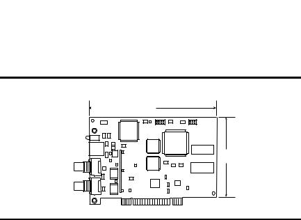
IMPORTANT |
The card’s dimensions are shown below. |
||||||
|
|
|
|
|
|
|
|
|
|
|
|
6.5 in. |
|||
|
|
|
|
|
16.5 cm |
||
|
|
|
|
|
|||
|
|
|
|
|
|
|
|
|
|
|
|
|
|
|
|
|
|
|
|
|
|
|
|
4.2 in.
10.7 cm
31474-M
Access the Computer’s PCI Local Bus Expansion Slots
To install the card, you must access the computer’s PCI local bus expansion slots. Follow these general steps, or refer to your computer’s user guide for further instructions.
1.Shut down the host computer.
2.Remove the computer’s cover.
3.Select a vacant PCI local bus expansion slot.
4.Loosen the screw (if present) on the back (rear bracket) of the computer.
5.Remove the slot’s expansion cover.
Publication 1784-IN003D-EN-P - January 2006
1-6 Install the 1784-PCIC or 1784-PCICS Communication Interface Card
Insert the Card Into the Computer
WARNING
When used in a Class I, Division 2, hazardous location, this equipment must be mounted in a suitable enclosure with proper wiring method that complies with the governing electrical codes.
If you insert or remove the card while host power is on, an electrical arc can occur. This could cause an explosion in hazardous location installations.
Be sure that power is removed or the area is nonhazardous before proceeding.
1.Handle the card so that you prevent electrostatic discharge. Refer to the Preface of this manual for more information.
2.Insert the card into the edge connector and tighten the expansion slot screw (if present).
3.Replace the computer cover.
4.Turn on the computer to be certain that it comes up correctly.
If the Computer |
Then |
|
|
Turns on |
Go to to the next section, Connect to the Network |
|
|
Hangs up |
Either the card is not seated correctly in the PCI slot or you have a |
|
memory or I/O conflict. You should: |
|
∙ remove and reinsert the card into the same PCI slot and |
|
try again |
|
∙ remove and reinsert the card into a different PCI slot and |
|
try again |
|
∙ remove all other non-essential cards and try again |
|
If you continue to experience difficulty, contact your local |
|
Rockwell Automation sales representative or distributor, or call |
|
Rockwell Automation Technical Support at 440.646.5800. |
|
|
Publication 1784-IN003D-EN-P - January 2006
Install the 1784-PCIC or 1784-PCICS Communication Interface Card |
1-7 |
|
|
Connect to the Network
WARNING
When used in a Class I, Division 2, hazardous location, this equipment must be mounted in a suitable enclosure with proper wiring method that complies with the governing electrical codes.
If you connect or disconnect the ControlNet cable with power applied to this module or any device on the network, an electrical arc can occur. This could cause an explosion in hazardous location installations.
Be sure that power is removed or the area is nonhazardous before proceeding.
After you have installed the card, you can connect it:
∙directly to a ControlNet network, which requires a tap (page 1-9).
∙to a device already connected to the ControlNet network (page 1-10).
See Figure 1.1 on page 1-8 for the connectors and indicators.
Publication 1784-IN003D-EN-P - January 2006
1-8 Install the 1784-PCIC or 1784-PCICS Communication Interface Card
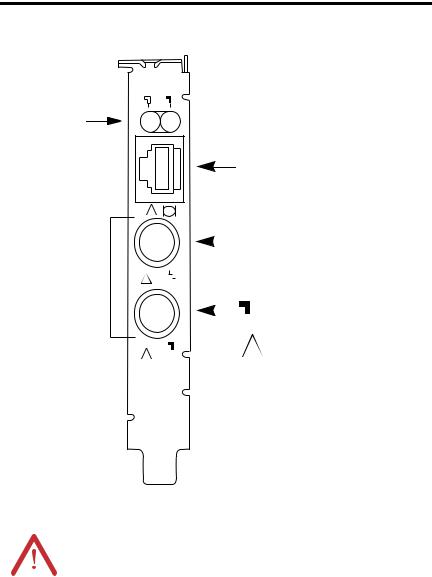
Figure 1.1 1784-PCIC or 1784-PCICS Card (1784-PCIC Card Shown)
Diagnostic Status
Indicators
Network Access Port (NAP)
RJ-45 connector for connecting programming terminals to devices on a ControlNet network
!
|
|
|
|
|
|
|
|
|
|
|
|
|
|
|
|
|
Channel A |
|
|
|
|
|
|
|
|
|
|
|
|
|
|
|
|
|
BNC connectors for connecting directly to |
|
|
|
|
|
|
|
|
|
|
|
|
|
|
|
|
|
|
|
Redundant Media |
|
|
|
|
A |
|
|
|
|
|
|
|
|
ControlNet network |
||
|
|
|
|
|
|
|
|
|
|
|
|
|
|||||
|
|
|
|
|
|
|
|
|
|
|
|
|
|
||||
|
BNC Connectors |
|
! |
|
|
|
|
|
|
|
|
|
|||||
|
|
|
|
|
|
|
|
|
|
|
|
|
|
|
|
|
Channel B |
|
|
|
|
|
|
|
|
|
|
|
|
|
|
|
|
|
|
|
|
|
|
|
|
|
|
|
|
|
|
|
|
|
|
|
|
|
|
|
|
|
|
|
|
|
|
|
|
|
|
|
|
|
Do not connect more than one |
|
|
|
|
|
|
|
|
B |
|
|
|
|
|
|
! ControlNet network to this card. |
||
|
|
|
|
|
|
|
! |
|
|
|
|
|
|
||||
|
|
|
|
|
|
||||||||||||
|
|
|
|
|
|||||||||||||
|
|
|
|
|
|
|
|
|
|
|
|
|
|
|
|||
|
|
|
|
|
Allen-Bradley |
|
|
|
|||||||||
|
|
|
|
|
|
|
1784-PCIC |
|
|
|
|||||||
|
|
|
|
|
|
ControlNet |
|
|
|
||||||||
|
|
|
|
|
|
|
|
|
|
|
|
|
|
|
42281 |
||
|
|
|
|
|
|
|
|
|
|
|
|
|
|
|
|
|
|
|
|
|
|
Do not connect different ControlNet networks to this card. If |
|||||||||||||
ATTENTION |
|
||||||||||||||||
|
you attempt to connect a second network to this card, your |
||||||||||||||||
|
|
|
|
||||||||||||||
|
|
|
|
communication system will operate erratically. |
|||||||||||||
|
|
|
|
|
|
|
|
|
|
|
|
|
|
|
|
|
|
|
|
|
|
|
|
|
|
|
|
|
|
|
|
|
|
|
|
|
|
|
|
|
|
|
|
|
|
|
|
|
|
|
|
|
|
Publication 1784-IN003D-EN-P - January 2006

Install the 1784-PCIC or 1784-PCICS Communication Interface Card |
1-9 |
|
|
Connect the Card Directly to the ControlNet Network
To connect the card directly to a ControlNet network, follow the instructions in these publications:
∙ControlNet Coax Tap Installation Instructions, publication 1786-IN007
∙ControlNet Coax Media Planning and Installation Manual, publication CNET-IN002
Figure 1.2 Connect the Card Directly to the ControlNet Network
1784-PCIC or
1784-PCICS Desktop Host Computer
1786-TPR, -TPS, -TPYR, or -TPYS Tap
ControlNet Network
42200
ATTENTION |
If you connect the product to a cable system that does not |
|
support redundant media, connect the tap dropline to the BNC |
||
|
||
|
connector labeled channel A. Channel B is left unconnected. |
If the cable system is redundant, connect the product so that all devices on the network use the same cable for the same channel. That is, all channel A connectors connect to one cable; all channel B connectors connect to the other cable.
TIP |
If you use a non-redundant cable system, all ControlNet |
|
devices must be on the same channel, channel A. |
||
|
Publication 1784-IN003D-EN-P - January 2006
1-10 Install the 1784-PCIC or 1784-PCICS Communication Interface Card
Connect to a Device on the ControlNet Network
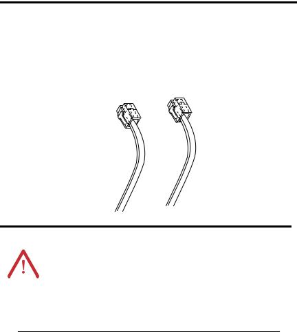
The 1786-CP cable (Figure 1.3) connects a host computer to another ControlNet device. It has two RJ-45 8-pin connectors.
Figure 1.3 1786-CP cable
RJ-45 8-pin Connectors
Connector 1 |
Connector 2 |
1786-CP Cable
30124-m
ATTENTION |
Use only the 1786-CP cable when you connect a |
|||
programming terminal to the network through the Network |
||||
|
|
|
||
|
|
|
Acces Port (NAP). If you use a different cable, it could |
|
|
|
|
result in possible network failures or product damage. |
|
|
|
|
|
|
|
|
|
|
|
|
|
|
|
|
See Tables 1.1 and 1.2 for the wiring for the 1786-CP cable.
Table 1.1 Wiring For 1786-CP Cable (Connector 1)
Connector 1
Wire Number |
Signal Mnemonic |
Signal Name |
|
|
|
1 |
ISO-GND |
Isolated Ground |
|
|
|
2 |
N.C. |
No Connection |
|
|
|
3 |
PTTX-H |
Transmit Data High |
|
|
|
4 |
PTTX-L |
Transmit Data Low |
|
|
|
5 |
PTRX-L |
Receive Data Low |
|
|
|
6 |
PTRX-H |
Receive Data High |
|
|
|
7 |
N.C. |
No Connection |
|
|
|
8 |
ISO-GND |
Isolated Ground |
|
|
|
Publication 1784-IN003D-EN-P - January 2006

|
|
Install the 1784-PCIC or 1784-PCICS Communication Interface Card |
1-11 |
||
|
|
|
|
|
|
|
Table 1.2 Wiring For 1786-CP Cable (Connector 2) |
|
|||
|
|
|
|
|
|
|
|
|
Connector 2 |
|
|
|
|
|
|
|
|
|
Wire Number |
|
Signal Mnemonic |
Signal Name |
|
|
|
|
|
|
|
1 |
|
ISO-GND |
Isolated Ground |
|
|
|
|
|
|
|
|
2 |
|
N.C. |
No Connection |
|
|
|
|
|
|
|
|
3 |
|
PTRX-H |
Receive Data High |
|
|
|
|
|
|
|
|
4 |
|
PTRX-L |
Receive Data Low |
|
|
|
|
|
|
|
|
5 |
|
PTTX-L |
Transmit Data Low |
|
|
|
|
|
|
|
|
6 |
|
PTTX-H |
Transmit Data High |
|
|
|
|
|
|
|
|
7 |
|
N.C. |
No Connection |
|
|
|
|
|
|
|
|
8 |
|
ISO-GND |
Isolated Ground |
|
|
|
|
|
|
|
|
When you use the RJ-45 connector, you can connect the card to a ControlNet network without a tap through the Network Access Port (or NAP) of a programmable controller, I/O adapter, or other ControlNet compliant devices.
See Figure 1.4 and Figure 1.5.
Publication 1784-IN003D-EN-P - January 2006

1-12 Install the 1784-PCIC or 1784-PCICS Communication Interface Card
Figure 1.4 Connect a Programming Terminal to a ControlNet Network Through Another ControlNet Device
Programming
Terminal
1784-PCIC or |
|
1784-PCICS |
1786-CP Cable1 |
ControlNet Network |
ControlNet |
|
Product |
|
42199 |
1The 1786-CP cable can be plugged into any ControlNet product’s NAP to provide programming capability on the ControlNet network. When you connect a programming terminal through this cable, it is counted as a node and must have a unique address.
ATTENTION |
If a SoftLogix5800 processor is running on the computer |
|||
containing the 1784-PCIC or 1784-PCICS card, do not use the |
||||
|
|
|
||
|
|
|
1786-CP cable to connect the card to the ControlNet network. |
|
|
|
|
Instead, connect the card directly to the ControlNet network as |
|
|
|
|
shown in Figure 1.2. |
|
|
|
|
||
|
|
|
||
Figure 1.5 Connect a Portable Host Computer to the ControlNet Network Through the 1784-PCIC or 1784-PCICS Card
|
|
1784-PCIC or |
Desktop Host |
Portable Host |
1784-PCC |
1784-PCICS |
|
|
Computer |
||
Computer |
|
|
|
|
|
|
1784-PCC1 Cable
ControlNet Network
42198
Publication 1784-IN003D-EN-P - January 2006

Chapter 2
Install the Driver in Windows XP
For Information On This Topic |
See Page |
Install the Driver in Windows XP for the First Time |
2-1 |
|
|
Update the Existing Driver in Windows XP |
2-3 |
|
|
Install the Driver in Windows XP for the First Time
Follow these steps to install the driver for the first time on a personal computer running Windows XP.
1.Shut down the computer.
2.Insert the 1784-PCIC or 1784-PCICS card into an unused PCI slot. Refer to Chapter 1 for installation information.
3.Restart the computer.
Publication 1784-IN003D-EN-P - January 2006

2-2 Install the Driver in Windows XP
After the computer restarts, the operating system detects the new PCI card and displays the Found New Hardware Wizard.
4.Select the Install from a list or specific location (Advanced) radio button.
5.Click Next.
6.On the screen that appears, click the Search for the best driver in these locations radio button.
7.Check the Include this location in the search checkbox.
8.Uncheck the remaining checkboxes.
Publication 1784-IN003D-EN-P - January 2006
Loading...