


 Loading...
Allen Bradley
Very High Speed
Counter Module
(Cat. No. 1771 VHSC Series B)
User
Manual

Important User Information
Because of the variety of uses for the products described in this publication, those responsible for the application and use of this control equipment must satisfy themselves that all necessary steps have been taken to assure that each application and use meets all performance and safety requirements, including any applicable laws, regulations, codes and standards.
The illustrations, charts, sample programs and layout examples shown in this guide are intended solely for example. Since there are many variables and requirements associated with any particular installation, Allen-Bradley does not assume responsibility or liability (to include intellectual property liability) for actual use based upon the examples shown in this publication.
Allen-Bradley publication SGI±1.1, ªSafety Guidelines For The Application, Installation and Maintenance of Solid State Controlº (available from your local Allen-Bradley office) describes some important differences between solid-state equipment and electromechanical devices which should be taken into consideration when applying products such as those described in this publication.
Reproduction of the contents of this copyrighted publication, in whole or in part, without written permission of Allen±Bradley Company, Inc. is prohibited.
Throughout this manual we make notes to alert you to possible injury to people or damage to equipment under specific circumstances.
ATTENTION: Identifies information about practices or circumstances that can lead to personal injury or death, property damage or economic loss.
Attention helps you:
Identify a hazard.
Avoid the hazard.
Recognize the consequences.
Important: Identifies information that is especially important for successful application and understanding of the product.
Important: We recommend you frequently backup your application programs on appropriate storage medium to avoid possible data loss.

Summary of Changes
Summary of Changes
Summary of Changes
This release of the publication contains new and updated information from the last release.
New Information
This release includes information on the Series B version of the 1771-VHSC module. This includes a new Appendix E on the differences between period/rate and continuous/rate modes of operation. This information was not included in the previous version of this publication.
Updated Information
This release includes updated information in Appendix C, ªapplication Considerations,º and revised Specifications in Appendix A.
Change Bars
To help you find new and updated information in this publication, we have included change bars as shown to the right of this paragraph.

Table of Contents
Summary of Changes . . . . . . . . . . . . . . . . . . . . . . . . |
SOC-1 |
Summary of Changes . . . . . . . . . . . . . . . . . . . . . . . . . . . . . |
SOC-1 |
New Information . . . . . . . . . . . . . . . . . . . . . . . . . . . . . . . . . |
SOC-1 |
Updated Information . . . . . . . . . . . . . . . . . . . . . . . . . . . . . . |
SOC-1 |
Change Bars . . . . . . . . . . . . . . . . . . . . . . . . . . . . . . . . . . . |
SOC-1 |
Using This Manual . . . . . . . . . . . . . . . . . . . . . . . . . . . . . . . |
|
P-1 |
Purpose of This Manual . . . . . . . . . . . . . . . . . . . . . . . . . . . . . . . |
|
P-1 |
Audience . . . . . . . . . . . . . . . . . . . . . . . . . . . . . . . . . . . . . . . . . . |
|
P-1 |
Vocabulary . . . . . . . . . . . . . . . . . . . . . . . . . . . . . . . . . . . . . . . . |
|
P-1 |
Manual Organization . . . . . . . . . . . . . . . . . . . . . . . . . . . . . . . . . |
|
P-1 |
Related Products . . . . . . . . . . . . . . . . . . . . . . . . . . . . . . . . . . . . |
|
P-2 |
. . . . . . . . . . . . . . . . . . . . . . . . . . . . . . . . .Product Compatibility |
|
P-2 |
. . . . . . . . . . . . . . . . . . . . . . . . . . . . . . . . . .Related Publications |
|
P-2 |
Overview of the Very High Speed Counter Module . . . . . . . |
1-1 |
Chapter Objectives . . . . . . . . . . . . . . . . . . . . . . . . . . . . . . . . . . . |
1-1 |
Module Description . . . . . . . . . . . . . . . . . . . . . . . . . . . . . . . . . . |
1-1 |
Features of the Module . . . . . . . . . . . . . . . . . . . . . . . . . . . . . . . . |
1-1 |
Operation in Encoder or Counter Mode . . . . . . . . . . . . . . . . . . . . |
1-2 |
Counter Mode . . . . . . . . . . . . . . . . . . . . . . . . . . . . . . . . . . . . . . |
1-3 |
Encoder Mode . . . . . . . . . . . . . . . . . . . . . . . . . . . . . . . . . . . . . . |
1-4 |
Preset Value . . . . . . . . . . . . . . . . . . . . . . . . . . . . . . . . . . . . . . . |
1-6 |
Rollover Value . . . . . . . . . . . . . . . . . . . . . . . . . . . . . . . . . . . . . . |
1-7 |
Software Reset . . . . . . . . . . . . . . . . . . . . . . . . . . . . . . . . . . . . . |
1-7 |
Gate/Reset Input . . . . . . . . . . . . . . . . . . . . . . . . . . . . . . . . . . . . |
1-7 |
Operation in Period/Rate Mode . . . . . . . . . . . . . . . . . . . . . . . . . . |
1-9 |
Continuous/Rate Mode . . . . . . . . . . . . . . . . . . . . . . . . . . . . . . . . |
1-12 |
Operation in Rate Measurement Mode . . . . . . . . . . . . . . . . . . . . . |
1-12 |
Outputs . . . . . . . . . . . . . . . . . . . . . . . . . . . . . . . . . . . . . . . . . . . |
1-14 |
Enabling and Forcing Outputs . . . . . . . . . . . . . . . . . . . . . . . . . . . |
1-14 |
Assigning Outputs to Counters . . . . . . . . . . . . . . . . . . . . . . . . . . |
1-14 |
Operation of Outputs . . . . . . . . . . . . . . . . . . . . . . . . . . . . . . . . . |
1-15 |
Handshaking . . . . . . . . . . . . . . . . . . . . . . . . . . . . . . . . . . . . . . . |
1-16 |
Default Configuration . . . . . . . . . . . . . . . . . . . . . . . . . . . . . . . . . |
1-16 |
How the Module Communicates with a Programmable Controller . . |
1-17 |
Chapter Summary . . . . . . . . . . . . . . . . . . . . . . . . . . . . . . . . . . . |
1-18 |
ii |
Table of Contents |
Installing the Very High Speed Counter Module . . . . . . . . . |
2-1 |
Chapter Objectives . . . . . . . . . . . . . . . . . . . . . . . . . . . . . . . . . . . |
2-1 |
European Union Directive Compliance . . . . . . . . . . . . . . . . . . . . . |
2-1 |
EMC Directive . . . . . . . . . . . . . . . . . . . . . . . . . . . . . . . . . . . . |
2-1 |
Low Voltage Directive . . . . . . . . . . . . . . . . . . . . . . . . . . . . . . . |
2-1 |
Electrostatic Damage . . . . . . . . . . . . . . . . . . . . . . . . . . . . . . . . . |
2-2 |
Power Requirements . . . . . . . . . . . . . . . . . . . . . . . . . . . . . . . . . |
2-2 |
Module Location in the I/O Chassis . . . . . . . . . . . . . . . . . . . . . . . |
2-2 |
Module Keying . . . . . . . . . . . . . . . . . . . . . . . . . . . . . . . . . . . . . . |
2-3 |
Setting the Configuration Jumpers . . . . . . . . . . . . . . . . . . . . . . . . |
2-4 |
Connecting Wiring . . . . . . . . . . . . . . . . . . . . . . . . . . . . . . . . . . . |
2-5 |
Grounding the VHSC Module Wiring . . . . . . . . . . . . . . . . . . . . . . |
2-6 |
Installing the Module . . . . . . . . . . . . . . . . . . . . . . . . . . . . . . . . . |
2-7 |
Interpreting the Indicator Lights . . . . . . . . . . . . . . . . . . . . . . . . . . |
2-8 |
Chapter Summary . . . . . . . . . . . . . . . . . . . . . . . . . . . . . . . . . . . |
2-8 |
Module Programming . . . . . . . . . . . . . . . . . . . . . . . . . . . . |
3-1 |
Chapter Objectives . . . . . . . . . . . . . . . . . . . . . . . . . . . . . . . . . . . |
3-1 |
Block Transfer Programming . . . . . . . . . . . . . . . . . . . . . . . . . . . . |
3-1 |
PLC 2 Program Example . . . . . . . . . . . . . . . . . . . . . . . . . . . . . . |
3-2 |
PLC 3 Program Example . . . . . . . . . . . . . . . . . . . . . . . . . . . . . . |
3-3 |
PLC 5 Program Example . . . . . . . . . . . . . . . . . . . . . . . . . . . . . . |
3-4 |
PLC 5/250 Program Example . . . . . . . . . . . . . . . . . . . . . . . . . . . |
3-5 |
Chapter Summary . . . . . . . . . . . . . . . . . . . . . . . . . . . . . . . . . . . |
3-5 |
Configuring Your Module . . . . . . . . . . . . . . . . . . . . . . . . . . |
4-1 |
Chapter Objectives . . . . . . . . . . . . . . . . . . . . . . . . . . . . . . . . . . . |
4-1 |
Configuring the VHSC Module . . . . . . . . . . . . . . . . . . . . . . . . . . . |
4-1 |
Configuration Block for a Block Transfer Write . . . . . . . . . . . . . . . |
4-2 |
Bit/Word Descriptions . . . . . . . . . . . . . . . . . . . . . . . . . . . . . . . . . |
4-3 |
Chapter Summary . . . . . . . . . . . . . . . . . . . . . . . . . . . . . . . . . . . |
4-7 |
Module Status and Input Data . . . . . . . . . . . . . . . . . . . . . . |
5-1 |
Chapter Objectives . . . . . . . . . . . . . . . . . . . . . . . . . . . . . . . . . . . |
5-1 |
Reading Data from the Module . . . . . . . . . . . . . . . . . . . . . . . . . . |
5-1 |
Block Transfer Read for the 1771 VHSC Module . . . . . . . . . . . . . . |
5-1 |
Bit/Word Description for Block Transfer Read . . . . . . . . . . . . . . . . |
5-3 |
Chapter Summary . . . . . . . . . . . . . . . . . . . . . . . . . . . . . . . . . . . |
5-4 |

Table of Contents |
iii |
Troubleshooting . . . . . . . . . . . . . . . . . . . . . . . . . . . . . . . .
Chapter Objectives . . . . . . . . . . . . . . . . . . . . . . . . . . . . . . . . . . .
Using the Indicators for Troubleshooting . . . . . . . . . . . . . . . . . . . .
Troubleshooting Chart . . . . . . . . . . . . . . . . . . . . . . . . . . . . . .
Diagnostic Codes Returned by the Module . . . . . . . . . . . . . . . . . .
Diagnostics Reported in Word 1 of BTR . . . . . . . . . . . . . . . . . .
Chapter Summary . . . . . . . . . . . . . . . . . . . . . . . . . . . . . . . . . . .
Specifications . . . . . . . . . . . . . . . . . . . . . . . . . . . . . . . . . .
Sample Programs . . . . . . . . . . . . . . . . . . . . . . . . . . . . . . .
Sample Program for PLC-2 Family Processors . . . . . . . . . . . . . .
Sample Program for PLC-5 Family Processors . . . . . . . . . . . . . .
Addditional Sample Program for PLC-5 Family Processors . . . . . .
Application Considerations . . . . . . . . . . . . . . . . . . . . . . . .
Appendix Objectives . . . . . . . . . . . . . . . . . . . . . . . . . . . . . . . . . .
Types of Input Devices . . . . . . . . . . . . . . . . . . . . . . . . . . . . . . . .
Examples for Selecting Input Devices . . . . . . . . . . . . . . . . . . . . .
Circuit Overview . . . . . . . . . . . . . . . . . . . . . . . . . . . . . . . . . . . . .
Detailed Circuit Analysis . . . . . . . . . . . . . . . . . . . . . . . . . . . . . . .
5V Differential Line Driver Example . . . . . . . . . . . . . . . . . . . . . . .
+12 to +24V Single Ended Driver . . . . . . . . . . . . . . . . . . . . . . . .
Open Collector . . . . . . . . . . . . . . . . . . . . . . . . . . . . . . . . . . . . . .
Supply Voltage verses Jumper Settings . . . . . . . . . . . . . . . . . .
Electromechanical Limit Switch . . . . . . . . . . . . . . . . . . . . . . . . . .
Output Circuits . . . . . . . . . . . . . . . . . . . . . . . . . . . . . . . . . . . . . .
Application Considerations . . . . . . . . . . . . . . . . . . . . . . . . . . . . .
Input Cable Length . . . . . . . . . . . . . . . . . . . . . . . . . . . . . . . . . . .
Totem pole Output Devices . . . . . . . . . . . . . . . . . . . . . . . . . . . . .
Cable Impedance . . . . . . . . . . . . . . . . . . . . . . . . . . . . . . . . . . . .
Cable Capacitance . . . . . . . . . . . . . . . . . . . . . . . . . . . . . . . . . . .
Cable Length and Frequency . . . . . . . . . . . . . . . . . . . . . . . . . . .
Questions and Answers . . . . . . . . . . . . . . . . . . . . . . . . . . .
General . . . . . . . . . . . . . . . . . . . . . . . . . . . . . . . . . . . . . . . . . . .
Questions and Answers . . . . . . . . . . . . . . . . . . . . . . . . . . . . . . .
Period/Rate and Continuous/Rate Examples . . . . . . . . . . .
General . . . . . . . . . . . . . . . . . . . . . . . . . . . . . . . . . . . . . . . . . . .
Changes made in Revision B . . . . . . . . . . . . . . . . . . . . . . . . . . .
Operation of Outputs in Period/rate Mode
(1771 VHSC Revision B Modules) . . . . . . . . . . . . . . . . . . . . .
Operation of Outputs in Continuous/Rate Mode . . . . . . . . . . . . . . .
6-1
6-1
6-1
6-1
6-2
6-2
6-2
A-1
B-1
B-1
B-2
B-4
C-1
C-1 C-1 C-1 C-2 C-3 C-4 C-5 C-6 C-6 C-7 C-7 C-8 C-8 C-8 C-9 C-9 C-9
D-1
D-1
D-1
E-1
E-1 E-2
E-3 E-4

Preface
Using This Manual
Purpose of This Manual
Audience
Vocabulary
Manual Organization
This manual shows you how to use the Very High Speed Counter module with an Allen-Bradley programmable controller. It helps you install, program, and troubleshoot your module.
You must be able to program and operate an Allen-Bradley programmable controller (PLC) to make efficient use of this module. In particular, you must know how to program your PLC for block transfer-type instructions.
We assume that you know how to do this in this manual. If you do not, refer to the appropriate programming and operations manual for the associated programmable controller before you attempt to use this module.
In this manual, we refer to:
•the Very High Speed Counter module as the ªmodule,º the ª1771-VHSCº or the ªVHSC module.º
•the programmable controller as the ªcontroller,º or the ªPLC.º
This manual is divided into six chapters. The following chart shows each chapter with its corresponding title and a brief description of the topics covered in that chapter.
Chapter |
Title |
Topics Covered |
|
|
|
|
|
|
|
|
|
Explanation of modes, outputs, default |
||
1 |
Overview of the Very High Speed Counter Module |
configuration and how the module communicates |
||
|
|
with the processor. |
||
|
|
|
||
2 |
Installing the Very High Speed Counter Module |
How to install, key, connect wiring, ground and an |
||
explanation of the indicators on the module. |
||||
|
|
|||
|
|
|
|
|
3 |
Module Programming |
Block transfer programming and programming |
||
examples. |
||||
|
|
|||
|
|
|
||
4 |
Configuring Your Module |
Configuration and description of bit/words for block |
||
transfer write instructions. |
||||
|
|
|||
|
|
|
||
5 |
Module Status and Input Data |
Reading data from the module and bit/word |
||
description of the block transfer read. |
||||
|
|
|||
|
|
|
||
6 |
Troubleshooting |
Using the indicators for troubleshooting and |
||
diagnostic codes. |
||||
|
|
|||
|
|
|
|
|

P±2 |
Using This Manual |
|
|
||
|
|
|
|
|
|
|
|
Chapter |
Title |
Topics Covered |
|
|
|
|
|
|
|
|
|
Appendices |
|
|
|
|
|
|
|
|
|
|
|
A |
Specifications |
Specifications for the VHSC module. |
|
|
|
|
|
|
|
|
|
B |
Sample Programs |
Sample programs for various PLC programs. |
|
|
|
|
|
|
|
|
|
C |
Application Considerations |
Selection of input devices and circuit descriptions. |
|
|
|
|
|
|
|
|
|
D |
Questions and Answers |
Helpful answers to the most asked questions. |
|
|
|
|
|
|
|
|
|
E |
Period/Rate and Continuous/Rate Examples |
Examples of the differences of these 2 modes |
|
|
|
|
|
|
|
Related Products
Product Compatibility
You can install your input module in any system that uses Allen-Bradley programmable controllers with block transfer capability and the 1771 I/O structure.
Contact your nearest Allen-Bradley office for more information about your programmable controllers.
This module can be used with any 1771 I/O chassis. Communication between the module and the processor is bidirectional. The PLC sends module information using block transfer write instructions and the 1771 I/O backplane. The PLC receives module status information through block transfer read instruction and places it in the data table. I/O image table use is an important factor in module placement and addressing selection. The module's data table use is listed in the following table.
Table P.A
Compatibility and Use of Data Table
Catalog |
|
Use of Data Table |
|
Compatibility |
|
|||
Input |
Output |
Read |
Write |
|
|
|
|
|
Number |
Image |
Image |
Block |
Block |
|
Addressing |
Chassis |
|
|
|
|||||||
|
Bits |
Bits |
Words |
Words |
1/2 slot |
1 slot |
2 slot Series |
|
|
|
|
|
|
|
|
|
|
1771 VHSC Rev. A |
8 |
8 |
18 max |
64 max |
Yes |
See note |
See note |
A and B |
|
|
|
|
|
|
|
|
|
1771 VHSC Rev. B |
8 |
8 |
26 max |
64 max |
Yes |
See note |
See note |
A and B |
|
|
|
|
|
|
|
|
|
A = Compatible with 1771 A1, A2, A4 chassis.
B = Compatible with 1771 A1B, A2B, A3B, A4B chassis.
Yes = Compatible without restriction
NOTE: Restricted to complementary module placement (refer to chapter 2)
Related Publications
For a list of publications with information on Allen-Bradley programmable controller products, consult our publication index SD499.

Chapter 1
Overview of the Very High
Speed Counter Module
Chapter Objectives
Module Description
This chapter gives you information on:
•features of the VHSC module
•how the module communicates with programmable controllers.
•how the module operates
The VHSC module performs high speed counting for industrial applications. The module is an intelligent block transfer I/O module that interfaces signals with any Allen-Bradley programmable controller that has block transfer capability. Block transfer programming moves module status data from the module's memory to a designated area in the processor data table. It also moves configuration words from the processor data table to the module memory.
The VHSC module is a single-slot module that does not require an external power supply. (Note: The outputs do require a power supply.) After scanning the inputs and updating the outputs, the input data is converted to a specified data type in a digital format to be transferred to the processor's data table on request. Command and configuration data is sent from the programmable controller data table to the module with a BTW instruction.
Features of the Module
The VHSC module counts pulses from encoders (such as Allen-Bradley Bulletin 845H, K, F, P, E and L), pulse generators or mechanical limit switches, proximity switches, etc. and returns either a count or frequency in binary or BCD format.
The module's features include:
•4 input channels configurable for encoder mode, counter mode, period/rate mode and continuous/rate mode
•8 outputs, isolated in groups of 2
•outputs are current-sourcing at 5 to 24V dc (2A maximum per output)
•single-ended or differential inputs
•2-phase encoder inputs up to a frequency of 250KHz
•single-phase counter inputs up to a frequency of 1MHz
•input voltage range of 5 to 24V dc
1±2 |
Overview of the Very High Speed Counter Module |
Operation in Encoder or Counter Mode
•returns in status either count or frequency in binary or BCD format
•input counts as high as 999,999
•up to 500KHz in period/rate or rate measurement frequency modes
•outputs can be tied to any counter
•each output has a user-selectable on-off value
•outputs can be tied back to an input for cascading
•automatic default configuration
•each counter has a user-selectable preset and rollover value
•period/rate w/periodic outputs and period/rate w/dynamic outputs can be used for totalization
The 1771-VHSC module operates in the following modes:
•counter mode
•encoder X1 mode
•encoder X4 mode
•period/rate mode
•rate measurement frequency mode
•continuous/rate mode
The operation of the module in these modes is described below.
The operation of encoder and counter modes is virtually identical. The only difference between the two modes is in the type of feedback used.
Use the counter mode if you need the module to read incoming pulses from a maximum of four encoders (single-ended or differential), counters, pulse generators, mechanical limit switches, etc. and return them to the programmable controller as a binary or BCD number (0-999,999). In counter mode, the module accepts only one channel feedback.
Use the encoder modes if you need the module to read incoming quadrature pulses and return them to the programmable controller as a binary or BCD number (0-999,999). In these modes, the module accepts two-phase quadrature feedback and counts up or down depending upon the condition of the phase B input for each counter.
The operation of the module in the encoder/counter modes is as follows:
Overview of the Very High Speed Counter Module |
1±3 |
•counter mode - channel B is tied high or low. Channel A input is used for pulse. The count is unidirectional with the direction determined by
channel B.
•encoder X1 - This is a bidirectional count mode; counting up or down, using quadrature input signals.
•encoder X4 - This is a bidirectional count mode, using quadrature input signals, with 4 times the resolution of X1.
Each of the counters in encoder/counter mode has values associated with it. These are:
•preset value
•rollover value
•gate/reset input
•output
Counter Mode
The counter mode allows the module to read incoming pulses and return them to the programmable controller processor as a binary or BCD number (0-999,999).
In the counter mode, direction (up counting or down counting) is determined by the phase B input, which can be a random signal. If Phase B is high, the counter will count down. If phase B is low or floating, (that is, not connected), the counter counts up.
If Phase B is: |
Counter will count (direction): |
|
|
High |
Down |
|
|
Low or floating (not connected) |
Up |
|
|
The module reads incoming pulses from a maximum of 4 encoders (single-ended or differential), counters, pulse generators, mechanical limit switches, and so forth and returns a count to the programmable controller processor in a binary or BCD number (0-999,999).

1±4 |
Overview of the Very High Speed Counter Module |
The counter mode accepts only one phase feedback. This relationship is shown in 1.1.
Figure 1.1
Block Diagram of Counter Mode
From Encoder/Pulse Generator
Phase A |
|
Terminal |
|
Phase B |
|
Terminal |
1771 VHSC |
(direction sense) |
|
Gate/Reset |
|
Terminal |
|
|
10677 I |
Encoder Mode
The encoder mode allows the module to read incoming pulses and return them to the programmable controller processor as a binary or BCD number (0-999,999).
In this mode, the module will accept two phase quadrature feedback. The module senses the relationship between the 2 phases and counts up or down accordingly.
Encoder X1 mode uses channel A for the pulse input. With B low (floating), the count direction is up; when B is high, the count direction is down.
Encoder X4 mode is identical to X1, except it uses quadrature signals on channel A and channel B, and counts on the leading and trailing edges of
A and B.

Overview of the Very High Speed Counter Module |
1±5 |
Figure 1.2
Block Diagram of Encoder Mode
From Encoder/Pulse Generator |
|
Phase A |
|
Terminal |
1771 VHSC |
|
|
Phase B |
|
Terminal |
|
(direction sense) |
|
Gate/Reset |
|
Terminal |
|
|
10678 I |
Direction of Count
The module can count either up or down, depending upon the condition of the B input for each counter. In encoder applications, the counter will increment on the leading edge of Phase A, while phase B determines the direction of the count.
You also have the option of X1 and X4 multiplying of the input pulses. 1.3 shows the relationships between phases A and B for forward and reverse directions in encoder applications.
1±6 |
Overview of the Very High Speed Counter Module |
Figure 1.3
Phase Relationship for Forward or Reverse Directions
Very High Speed
Counter Module
Phase A
Encoder
Input A
Encoder
Input B
Forward Rotation |
Phase B |
Reverse Rotation |
|
||
CCW Encoder Rotation |
|
CW Encoder Rotation |
Phase A
|
|
|
|
|
|
|
|
|
|
T |
|
|
|
|
|
|
|
|
|
|
|
|
|
|
|
|
|
|
|
|
|
|
|
|
|
|
|
|
|
|
|
|
|
|
|
|
|
|
|
|
|
|
|
|
|
|
|
4μsec |
|
|
|
|
|
|
|
|
|
|
|
|
|
|
|
|
|
|
|
|
|
|
|
|
|
|
|
|
|
|
|
|
|
|
|
|
|
||
|
|
|
|
|
|
|
|
|
|
min |
|
|
|
|
|
|
|
|
|
|
|
|
|
|
|
|
|
|
|
|
|
|
|
|
|
|
|
|
|
|
|
|
|
|
|
|
|
|
Phase B |
|
|
|
|
|
|
|
|
|
|
|
|
|
|
|
|
|
|
|
|
|
|
|
|
|
|
|
|
|
|
|
|
|
|
|
|
|
|
|
|
|
|
|
|||||
|
|
|
|
|
|
|
|
|
|
|
|
|
|
|
|
|
|
|
|
|
|
|
|
|
|
|
|
|
|
|
|
|
|
|
|
|
|
|
|
|
|
|
||||||
|
|
|
|
|
|
|
|
|
|
|
|
|
|
|
|
|
|
|
|
|
|
|
|
|
|
|
|
|
|
|
|
|
|
|
|
|
|
|
|
|
|
|
|
|
|
|
|
|
|
|
|
|
|
|
90 |
|
|
|
|
|
|
|
|
|
|
|
|
|
|
|
|
|
|
|
|
|
|
|
|
|
|
|
|
|
|
|
|
|
|
|
|
|
|
|
|
|
|
1μsec |
|
|
|
|
|
|
|
|
|
|
|
|
|
|
|
|
|
|
|
|
|
|
|
90 |
|
|
|
|
|
|
|
|
|
|
|
|
|
|
|
|
|
|||||||
|
|
|
|
|
|
|
|
|
|
|
|
|
|
|
|
|
|
|
|
|
|
|
|
|
|
|
|
2 |
|
|
|
|
|
1 |
|
|
|
|
|
0 |
|
|||||||
Typical |
|
|
1 |
|
|
|
|
|
|
|
2 |
|
|
|
|
3 |
|
|
|
|
|
|
|
|
|
|
|
|
|
|
|
|
|
|
|
|
|
|
|
|
|
|||||||
|
|
|
|
|
|
|
|
|
|
|
|
|
|
|
|
|
|
|
|
|
|
|
|
|
|
|
|
|
|
|
|
|
|
|
|
|
|
|
|
|
||||||||
|
|
|
|
|
|
|
|
|
|
|
|
|
|
|
|
|
|
|
|
|
|
|
|
|
|
|
|
|
|
|
|
|
|
|
|
|
|
|
|
|
|
|
|
|
|
|||
X1 |
|
|
|
|
|
|
|
|
|
|
|
|
|
|
|
|
|
|
|
|
|
|
|
|
|
|
|
|
|
|
|
|
|
|
|
|
|
|
|
|
|
|
|
|||||
|
|
|
|
|
|
|
|
|
|
|
|
|
|
|
|
|
|
|
|
|
|
|
|
|
|
|
|
|
|
|
|
|
|
|
|
|
|
|
|
|
|
|
|
|||||
Multiplying |
|
|
|
|
|
|
|
|
|
|
|
|
|
|
|
|
|
|
|
|
|
|
|
|
|
|
|
|
|
|
|
|
|
|
|
|
|
|
|
|
|
|
|
|
||||
|
|
|
|
|
|
|
|
|
|
|
|
|
|
|
|
|
|
|
|
|
|
|
|
|
|
|
|
|
|
|
|
|
|
|
|
|
|
|
|
|
|
|
|
|
||||
1 |
2 |
3 |
4 |
|
5 |
6 |
7 |
8 |
9 |
10 |
11 |
12 |
12 |
|
11 |
10 |
|
9 |
8 |
7 |
6 |
|
5 |
4 |
3 |
2 |
|
1 |
0 |
|||||||||||||||||||
X4
Multiplying
10679 I
The following paragraphs apply to both encoders and counters.
Preset Value
Each of the 4 counters has one preset value associated with it. In the encoder or counter modes, the preset value represents a reference point (or count) from which the module begins counting. The module can count either up or down from the preset value. Preset values are loaded into the count registers through the preset count bits. (Refer to word 1, bits 8-11 of the block transfer write initialization block in chapter 5.) Preset values can range from 0 to 999,999 binary or BCD.
Overview of the Very High Speed Counter Module |
1±7 |
Rollover Value
Each of the 4 counters has one rollover value associated with it. When the rollover value is reached by the encoder/counter, it resets to 0 and begins counting again. The rollover values range from 0 to 999,999 binary or BCD (0 represents 1,000,000). The rollover value is circular (for example: if you program 360, the count will be from 358, 359, 0, 1 etc. in a positive direction and from 1, 0, 359, 358 etc. in a negative direction).
Software Reset
The counters can also be reset by the Reset Count bits found in Word 1, bits 0-3 of the block transfer write. When one of these bits is set to 1, the associated counter is reset to zero and begins counting. The module can also be reset with the gate/reset as explained below. Refer to chapter 4 for further details.
Gate/Reset Input
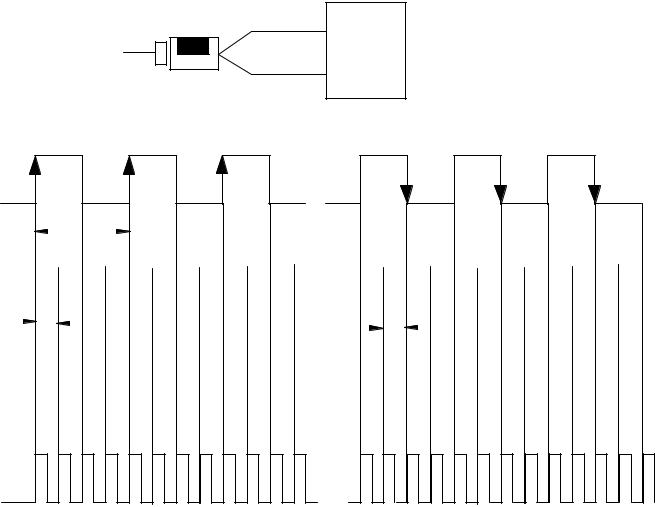
There is one gate/reset input for each of the 4 counters. The gate/reset input, when active, will function in one of the 4 store count modes outlined below.
Scaling Input Count at the Gate/Reset Terminal
You can scale the incoming count at the gate/reset terminal. Scaling allows the incoming pulses at gate/reset to be divided by a number in the range of 1, 2, 4, 8, 16, 32, 64 and 128. Refer to words 21 to 24 in the BTW file (chapter 4).
Store Count
The store count feature allows the module to store the current count value of any (or all) of the four counters. The store count feature is triggered by the state of the gate/reset terminal on the module. The stored count of each counter is placed in a separate word in the Block Transfer Read file (words 11-18 respectively). The stored count value will remain in the block transfer read file until a new trigger pulse is received at the Gate/Reset terminal. When a new trigger pulse is received, the old count value will be overwritten by the new value.
The store count feature is selected by words 3 and 4 of the block transfer write initialization file. Refer to chapter 4 for further details.

1±8 |
Overview of the Very High Speed Counter Module |
In mode 1, store/continue (1.4), the leading edge of a pulse input on the gate/reset terminal will cause the current value in the counter to be read and stored. The counter will continue counting. The stored count will be available in the block transfer read file. The stored count information will remain in the block transfer read file until it is overwritten by new data.
Figure 1.4
Store/Continue
Read, Store Count and continue counting.
10680 I
In mode 2, store/wait/resume (1.5), the gate/reset terminal provides the capability to inhibit counting when the gate/reset input is high. Counting resumes when the input goes low. Mode 2 does not reset the counter, although it does store the count value.
Figure 1.5
Store/Wait/Resume
Stop counting
Resume counting
Store Count
10681 I
In mode 3, store-reset/wait/start (1.6), the rising edge of the pulse on the gate/reset terminal causes the counter to stop counting, store the current count value in the block transfer read file and reset the count to zero. The counter does not count while the input pulse on the gate/reset terminal remains high. Counting resumes from zero on the falling edge of the pulse at the gate/reset terminal.
Figure 1.6
Store Reset/Wait/Start
Counter has stopped counting |
|
||
Stop count, store |
|
Start counting |
|
|
from zero |
||
and reset to zero |
|||
|
|||
10682 I
In mode 4, store-reset/start (1.7), on the rising edge of a pulse input at the gate/reset terminal will cause the counter to store the accumulated count value and will reset the counter to zero. The counter continues counting, and the stored count is available in the block transfer read file.

Overview of the Very High Speed Counter Module |
1±9 |
Operation in
Period/Rate Mode
Store Count, reset to zero, start counting.
Figure 1.7
Store Reset/Start
Rising Edge |
Falling Edge |
Store Count, reset to zero, start counting.
10683 I
Figures 1.4 through 1.7 show the store count feature operating on the rising edge of the gate/reset pulse. The user has the option of selecting these same features using the falling edge of the gate/reset pulse. This selection is made through the gate invert bit as explained in chapter 4.
The gate invert bit is active in the store count, continuous/rate and period/rate modes.
The stored count values are saved in words 11 through 18 of the block transfer read file (chapter 4).
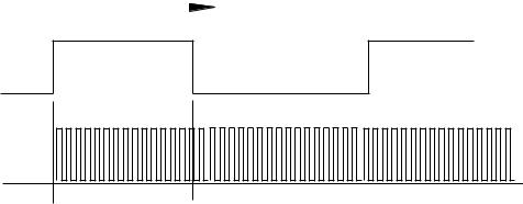
Use the period/rate mode to determine the frequency of input pulses by counting the number of internal 4MHz clock pulses over a user-specified number of input signal pulses. At the end of the specified number of pulses, the module returns the frequency and the number of internal 4MHz pulses.
A channel configured for period/rate mode acts as a period rate counter. An internal 4 MHz clock is used as a frequency reference. This clock is gated by the incoming pulse train at the gate/reset input. The results of this gating action are the number of pulses or a frequency. The number of sampled gated 4MHz pulses are returned in BTR words 3 thru 10, and the frequency in words 11 thru 18. Select the period/rate mode by setting the appropriate bits in words 3 and 4 of the BTW initialization file (chapter 4). The store count features are inactive in period/rate mode.
1771-VHSC revision B and later modules count the total number of pulses occurring at the gate/reset pin. This function is frequency-limited. This total count is returned when you request words 19 through 26 in your BTR. You can reset this count by resetting the reset bit (bits 0-4 in BTW
word 1). Rollover and preset are inactive. Refer to appendix E for additional information.
1.8 shows a diagram of the module used in the period/rate mode.
1±10 |
Overview of the Very High Speed Counter Module |
Figure 1.8
Period/Rate Mode
|
|
|
|
|
|
A Not used |
1771 VHSC |
||||||||
|
|
|
|
|
|
|
|
|
|
|
|
|
|
|
|
From user’s encoder/pulse generator |
B Not used |
|
|
|
|
|
|
|
|
|
|||||
|
|
|
|
|
|
|
|
|
|
|
|
|
|
|
|
|
|
|
|
|
Gate/Reset Terminal |
|
|
|
|
|
|
|
|
|
|
|
|
|
|
|
From internal 4MHz clock |
||||||||||
|
|
|
|
||||||||||||
|
|
|
|
|
|
|
|||||||||
|
|
|
|
|
|
|
|
|
|||||||
|
|
|
|
|
|
|
scaler |
|
|||||||
|
|
|
|
|
|
|
|
|
|||||||
|
|
|
|
|
|
|
|
|
|
|
|
|
|
|
|
|
|
|
|
|
|
|
|
|
|
|
|
|
|
|
|
Incoming pulse train at gate/reset terminal
Sampled pulses
4MHz internal clock
10684 I
In 1.8, the incoming pulse train from the gate/reset terminal is used to sample pulses from the 4 MHz internal clock. As the frequency of the incoming pulse train at the gate/reset terminal increases, the number of sampled pulses from the 4 Mhz clock decreases. This relationship is shown in Table 1.A. Since accuracy is related to the number of pulses received over the sample period, the accuracy will decrease with increasing input frequencies at the Gate/Reset terminal. To some extent, the decrease in accuracy can be lessened by scaling the input frequency through the use of a scaler. A scaler value of 1 will only return an accurate input frequency if incoming pulses have a 50% duty cycle. If frequency exceeds 500KHz, the number 999,999 is returned.

Overview of the Very High Speed Counter Module |
1±11 |
Table 1.A
Relationship Between Sampled Pulses and Input Frequency
Input Frequency at Gate/Reset |
Sampled Pulses for 1/2 Cycle |
Terminal in Hz |
of Gate/Reset Pulse |
(words 11 18 in BTR) |
(words 3 10 in BTR) |
|
|
2 |
1 meg |
|
|
5 |
400K |
|
|
10 |
200K |
|
|
20 |
100K |
|
|
50 |
40K |
|
|
100 |
20K |
|
|
200 |
10K |
|
|
500 |
4K |
|
|
1KHz |
2K |
|
|
2KHz |
1K |
|
|
5KHz |
400 |
|
|
10KHz |
200 |
|
|
20KHz |
100 |
|
|
50KHz |
40 |
|
|
100KHz |
20 |
|
|
200KHz |
10 |
|
|
Operation of scaler
In period/rate mode, the scaler lets the incoming pulse train at the gate/reset pin be divided by a user defined number. Acceptable values for the scaler are 1, 2, 4, 8, 16, 32, 64 and 128. There is one scaler value for each counter. The default value for each scaler is 1. Note: A 0 is equivalent to 1.
|
ATTENTION: Sample period times scaler must be |
|
! |
less than 0.25 seconds or the counter will overflow |
|
without providing an overflow indication. |
||
|
||
|
|
Connection to Counter Inputs
The only input to the module in the period/rate mode is made to the gate/reset terminal. The counter inputs (channel A and B) are not used in the period/rate mode.

1±12 |
Overview of the Very High Speed Counter Module |
Continuous/Rate Mode
Incoming pulse train at gate/reset terminal
4MHz internal clock
Period/rate
Continuous/rate
Operation in Rate
Measurement Mode
The continuous/rate mode is similar to the period/rate mode previously described except the outputs in this mode are dynamic outputs. Use this mode to determine the frequency of input pulses by counting the number of internal 4MHz clock pulses over a user-specified number of input signal pulses. Each output is turned on as soon as the turn-on count is reached, and turned off as soon as the turn-off count is reached. As the internal 4MHz clock is counted, the outputs dynamically track the 4MHz count. This allows you to turn an output on a certain number of 4MHz counts after the gate/reset pin goes active, and turn it off a certain number of 4MHz counts later.
1771-VHSC revision B and later modules count the total number of pulses occurring at the gate/reset pin. This function is frequency-limited. This total count is returned when you request words 19 through 26 in your BTR. You can reset this count by resetting the reset bit (bits 0-4 in BTW
word 1). Rollover and preset are inactive. Refer to appendix E for additional information.
Figure 1.9
Period/Rate and Continuous/Rate Output Operation with
Scaler of 1
Sampled pulses
Output on/off presets active only on scaler number pulse.
Output on/off presets active during entire
pulse.
10684 I
Use the rate measurement mode to count incoming pulses for a user-specified time interval. At the end of the interval, the module returns a value representing the sampled number of pulses and a value indicating the incoming frequency. When the count and frequency are updated, any associated outputs are checked against their associated presets.
Overview of the Very High Speed Counter Module |
1±13 |
The value representing the sampled number of pulses is returned in BTR words 3 thru 10, and the value indicating the incoming frequency is returned in words 11-18. The total count equals the number of pulses received during the sample period. The operation of rate measurement mode is shown below in 1.10.
Figure 1.10
Operation of the Rate Measurement Mode
From user’s encoder/pulse generator
|
|
|
|
|
|
|
|
|
Channel A |
1771 VHSC |
|
|
|
|
|
|
|
|
|
|
Module |
|
|
|
|
|
|
|
|
|
|
Channel B (not used)
Gate/Reset terminal (not used)
From user’s encoder/pulse generator
User selectable sample time
10685 I
Example:
In 1.10, three counts have been accumulated during the user-selected time period. If you had selected 50 milliseconds as the sample period, the frequency returned to the programmable controller processor in words 11-12 would be:
Frequency = Counts/Sample period = 3 counts/50 milliseconds = 60
Hz
You would read 60 Hz as the frequency in the Block Transfer Read file (words 11 and 12). Words 3 and 4 would contain the value 3. Since the default configuration for the VHSC module is the Counter mode, the user must select the rate measurement mode through the block transfer write initialization file. This is done by setting the appropriate bits in words 3 and 4 of the block transfer write initialization file (chapter 4). If frequency exceeds 500KHz, the number 999,999 is returned.
1±14 |
Overview of the Very High Speed Counter Module |
Outputs
Sample Period
You can set the sample period used in the frequency calculation in the rate measurement mode. Allowable values are 10 milliseconds to 2 seconds in 10 millisecond increments. The default value is 1 second. (Note: A 0 in the BTW initialization word is equivalent to the default value of 1 second.)
The sample period is set in words 21 through 24 of the BTW initialization file (chapter 4).
Connection to Counter Inputs
The only user connections used in the rate measurement mode are to phase A of the module. The gate/reset and channel B terminals are not used in this mode.
The VHSC module has 8 outputs, isolated in groups of 2. Each of the outputs is capable of sourcing current and will operate between 5 and 24 volts dc. You must connect an external power supply to each of the outputs. The outputs can source 2 amps dc. The outputs are hardware-driven and will turn on in less than 10μsec when the appropriate count value has been reached.
Enabling and Forcing Outputs
Outputs may be forced on or off independent of count or frequency value. To force the outputs, they must first be enabled. Enabling the outputs is done through a data table word 2, bits 0-7 in the BTW initialization file (chapter 4). Once the outputs have been enabled, they may be forced on by setting bits 8-15 in word 2 of the BTW initialization file. The outputs can be forced off by setting the enable bit to 0.
Assigning Outputs to Counters
By setting bits in the block transfer write initialization file, you can assign the outputs on the module to any of the various counters. You can assign as many as 8 outputs to a given counter. However, an output may be assigned only once to a counter--it is not possible to use the same output with 2 different counters. Refer to words 25, 30, 35, 40, 45, 50, 55, 60 of the BTW initialization file in chapter 4.

Overview of the Very High Speed Counter Module |
1±15 |
Operation of Outputs
When the outputs for the VHSC module are enabled and assigned to a counter they operate in an ON-OFF fashion. For example, assume that the module were programmed to turn ON an output when a count value of 2000 was reached. Further, assume that the user desired to have the output remain energized for a period of 3000 counts and then turn OFF. The end result would be that the outputs would turn ON at count of 2000, would remain energized for 3000 additional counts, and would turn OFF at 5000 counts. The ON and OFF values are circular around zero. In the rate measurement mode, the On and Off values associated with each output represent a frequency value instead of a count value. The maximum frequency value which may be entered in an On or Off value is 500,000Hz. Refer to 1.11.
Figure 1.11
On Off Operation of Output
Output remains energized for 3000 additional counts
Output turns on at count value of 2000 |
|
Output turns off at count value of 5000 |
||
|
||||
|
|
|
||
|
|
|
|
10686 I |
Refer to 1.12. Using output 0 as an example, when the value in words 26 and 27 is less than the value in words 28 and 29, the output turns on at 2000 and off at 5000. If the value in words 26 and 27 is greater than the value in words 28 and 29, the output turns off at 2000 and on at 5000.
Figure 1.12
Effect of Values in Words 26 through 29
|
|
Output remains energized |
|
|
|
|
|
||
|
|
for 3000 additional counts. |
|
|
|
|
|
||
|
|
Output turns OFF |
|
Output turns ON |
|||||
Output turns ON |
|
Output turns OFF |
|
||||||
|
at count of 2000. |
|
at count of 5000. |
||||||
at count of 2000. |
|
at count of 5000. |
|
||||||
|
|
|
|
|
|
||||
|
|
|
|
|
|
|
|
|
|
When values in words 26 27 are less than values in words 28 29.
When values in words 26 27 are greater than values in words 28 29.
10687 I
Refer to words 26-29, 31-34, 36-39, 41-44, 46-49, 51-54, 56-59, 61-64 of the block transfer write initialization file in chapter 5.
Isolation of Outputs
The module provides 1500V ac forced rms isolation between each of the counters and the backplane of the I/O rack.

1±16 |
Overview of the Very High Speed Counter Module |
Default Configuration
Tying Outputs to Counters
You can jumper any of the outputs to any of the counter inputs on the module field wiring arm. In this way, it is possible to use the outputs to reset a counter or to cascade counters. If using the outputs this way, make certain that the input voltage jumpers are set to interface with the appropriate output voltage.
Handshaking
A pair of handshaking bits are provided for each counter. These bits are called New Data (ND) bits in the BTR instruction, and New Data Acknowledge (NDA) bits in the BTW instruction. They indicate when a stored data value has been most recently updated. These bits are provided for count/accumulate applications, but can be used whenever the stored data is updated at a rate slower than the block transfer time.
The New Data bit (BTR status word 1, bits 4-7 for counters 0-3 respectively) can be used by the ladder program to indicate that a store register (BTR words 11-18) has been updated by one of the following events:
An active gate transition in any of the store count modes
The end of the gate sample period in either the period/rate or continuous/rate modes
The end of the programmed sample period in rate measurement mode
The ND bit is reset in the ladder program by a 0 to 1 transition of the corresponding NDA bit, and then performing a BTW. A BTW length of 1 word can be use for this handshaking procedure.
Note: A BTW length of 1 has no effect on the preset or reset bits in BTW word 1, and does not qualify as a configuration BTW. (For example, if the BTW valid bit is set, it will remain set after the BTW with a length of 1 is sent.)
A default configuration is built into the module. The default configuration is automatically selected on power-up if the user has not configured the module through a Block Transfer Write Initialization file. The module can be placed in the default configuration by writing a block transfer write initialization file with all zeroes to the module.
Loading...