


 Loading...
User Manual
Stratix 8000 and 8300 Ethernet Managed Switches

Important User Information
Read this document and the documents listed in the additional resources section about installation, configuration, and operation of this equipment before you install, configure, operate, or maintain this product. Users are required to familiarize themselves with installation and wiring instructions in addition to requirements of all applicable codes, laws, and standards.
Activities including installation, adjustments, putting into service, use, assembly, disassembly, and maintenance are required to be carried out by suitably trained personnel in accordance with applicable code of practice.
If this equipment is used in a manner not specified by the manufacturer, the protection provided by the equipment may be impaired.
In no event will Rockwell Automation, Inc. be responsible or liable for indirect or consequential damages resulting from the use or application of this equipment.
The examples and diagrams in this manual are included solely for illustrative purposes. Because of the many variables and requirements associated with any particular installation, Rockwell Automation, Inc. cannot assume responsibility or liability for actual use based on the examples and diagrams.
No patent liability is assumed by Rockwell Automation, Inc. with respect to use of information, circuits, equipment, or software described in this manual.
Reproduction of the contents of this manual, in whole or in part, without written permission of Rockwell Automation,
Inc., is prohibited.
Throughout this manual, when necessary, we use notes to make you aware of safety considerations.
WARNING: Identifies information about practices or circumstances that can cause an explosion in a hazardous environment, which may lead to personal injury or death, property damage, or economic loss.
ATTENTION: Identifies information about practices or circumstances that can lead to personal injury or death, property damage, or economic loss. Attentions help you identify a hazard, avoid a hazard, and recognize the consequence.
IMPORTANT Identifies information that is critical for successful application and understanding of the product.
Labels may also be on or inside the equipment to provide specific precautions.
SHOCK HAZARD: Labels may be on or inside the equipment, for example, a drive or motor, to alert people that dangerous voltage may be present.
BURN HAZARD: Labels may be on or inside the equipment, for example, a drive or motor, to alert people that surfaces may reach dangerous temperatures.
ARC FLASH HAZARD: Labels may be on or inside the equipment, for example, a motor control center, to alert people to potential Arc Flash. Arc Flash will cause severe injury or death. Wear proper Personal Protective Equipment (PPE). Follow ALL Regulatory requirements for safe work practices and for Personal Protective Equipment (PPE).
Allen-Bradley, Rockwell Software, Rockwell Automation, Logix5000, RSLinx, RSLogix, RSNetWorx, Stratix 2000, Stratix 5700, Stratix 8000, Stratix 8300, Studio 5000, and Studio 5000 Logix Designer are trademarks of Rockwell Automation, Inc.
Trademarks not belonging to Rockwell Automation are property of their respective companies.

Summary of Changes
New and Updated
Information
This manual contains new and updated information. Changes throughout this revision are marked by change bars, as shown to the right of this paragraph.
This table contains the changes made to this revision.
Topic |
Page |
|
|
Updated Device Manager hardware and software requirements |
48, 53 |
|
|
New Express Setup window |
50, 51 |
|
|
New process for enabling static and connected routing |
83, 84 |
|
|
New DeviceManager Web interface |
87…139 |
|
|
Rockwell Automation Publication 1783-UM003I-EN-P - March 2014 |
3 |

Summary of Changes
Notes:
4 |
Rockwell Automation Publication 1783-UM003I-EN-P - March 2014 |

|
|
Table of Contents |
Preface |
Studio 5000 Environment . . . . . . . . . . . . . . . . . . . . . . . . . . |
. . . . . . . . . . . . . . 11 |
|
Access Product Release Notes . . . . . . . . . . . . . . . . . . . . . . . . |
. . . . . . . . . . . . . 12 |
|
Additional Resources . . . . . . . . . . . . . . . . . . . . . . . . . . . . . . . . |
. . . . . . . . . . . . . 13 |
|
Chapter 1 |
|
Install the Switch |
Before You Begin . . . . . . . . . . . . . . . . . . . . . . . . . . . . . . . . . . . |
. . . . . . . . . . . . . 17 |
|
Parts List . . . . . . . . . . . . . . . . . . . . . . . . . . . . . . . . . . . . . . . |
. . . . . . . . . . . . . 18 |
|
Required Tools and Equipment. . . . . . . . . . . . . . . . . . . |
. . . . . . . . . . . . . 19 |
|
Product Dimensions . . . . . . . . . . . . . . . . . . . . . . . . . . . . . |
. . . . . . . . . . . . . 20 |
|
Install the Switch. . . . . . . . . . . . . . . . . . . . . . . . . . . . . . . . . . . . |
. . . . . . . . . . . . . 21 |
|
Attach Expansion Modules (optional) . . . . . . . . . . . . . . . . |
. . . . . . . . . . . . . 22 |
|
Mount the Switch on a DIN Rail . . . . . . . . . . . . . . . . . . . . . |
. . . . . . . . . . . . . 24 |
|
Mount the Switch on a Wall or Panel . . . . . . . . . . . . . . . . . |
. . . . . . . . . . . . . 26 |
|
Install an SFP Module (optional) . . . . . . . . . . . . . . . . . . . . . |
. . . . . . . . . . . . . 27 |
|
Ground the Switch . . . . . . . . . . . . . . . . . . . . . . . . . . . . . . . . . . |
. . . . . . . . . . . . . 28 |
|
Wire the DC Power Source for the Switch . . . . . . . . . . . . |
. . . . . . . . . . . . . 29 |
|
Wire the DC Power Source for the PoE Expansion Module (optional) . 31 |
|
|
Attach the Power and Relay Connector to the Switch . . |
. . . . . . . . . . . . . 33 |
|
Attach the Power Connector to the PoE Expansion Module (optional). 35 |
|
|
Wire External Alarms (optional) . . . . . . . . . . . . . . . . . . . . . |
. . . . . . . . . . . . . 35 |
|
Connect to 10/100 Copper Ports . . . . . . . . . . . . . . . . . . . . |
. . . . . . . . . . . . . 37 |
|
Connect to a PoE Expansion Module Port . . . . . . . . . . . . |
. . . . . . . . . . . . . 37 |
|
Connect to Dual-purpose Uplink Ports . . . . . . . . . . . . . . . |
. . . . . . . . . . . . . 38 |
|
Connect to 10/100/1000 Uplink Ports . . . . . . . . . . . |
. . . . . . . . . . . . . 38 |
|
Connect to SFP Fiber Ports . . . . . . . . . . . . . . . . . . . . . . |
. . . . . . . . . . . . . 38 |
|
Connect to 100BaseFX Ports . . . . . . . . . . . . . . . . . . . . . . . . |
. . . . . . . . . . . . . 39 |
|
Install or Remove the CompactFlash Card . . . . . . . . . . . . |
. . . . . . . . . . . . . 39 |
|
Reset the Switch to Factory Defaults . . . . . . . . . . . . . . . . . . |
. . . . . . . . . . . . . 40 |
|
Troubleshoot the Installation . . . . . . . . . . . . . . . . . . . . . . . . |
. . . . . . . . . . . . . 40 |
|
Switch POST Results . . . . . . . . . . . . . . . . . . . . . . . . . . . . |
. . . . . . . . . . . . . 40 |
|
POST Results with a Terminal . . . . . . . . . . . . . . . . . . . |
. . . . . . . . . . . . . 40 |
|
Bad or Damaged Cable. . . . . . . . . . . . . . . . . . . . . . . . . . . |
. . . . . . . . . . . . . 41 |
|
Ethernet and Fiber Cables. . . . . . . . . . . . . . . . . . . . . . . . |
. . . . . . . . . . . . . 41 |
|
Link Status . . . . . . . . . . . . . . . . . . . . . . . . . . . . . . . . . . . . . |
. . . . . . . . . . . . . 42 |
|
Transceiver Issues . . . . . . . . . . . . . . . . . . . . . . . . . . . . . . . |
. . . . . . . . . . . . . 42 |
|
Port and Interface Settings . . . . . . . . . . . . . . . . . . . . . . . |
. . . . . . . . . . . . . 42 |
|
Chapter 2 |
|
Getting Started |
Switch Front Panel Description . . . . . . . . . . . . . . . . . . . . . . |
. . . . . . . . . . . . . 44 |
|
Expansion Module Front Panel Descriptions . . . . . . . . . . |
. . . . . . . . . . . . . 44 |
|
Hardware Features . . . . . . . . . . . . . . . . . . . . . . . . . . . . . . . . . . |
. . . . . . . . . . . . . 47 |
|
CompactFlash Memory Card . . . . . . . . . . . . . . . . . . . . . . . . |
. . . . . . . . . . . . . 48 |
|
Set Up the Switch Initially with Express Setup. . . . . . . . . |
. . . . . . . . . . . . . 48 |
|
Switch Memory Allocation . . . . . . . . . . . . . . . . . . . . . . . . . . |
. . . . . . . . . . . . . 52 |
|
Device Manager Web Interface. . . . . . . . . . . . . . . . . . . . . . . |
. . . . . . . . . . . . . 53 |
Rockwell Automation Publication 1783-UM003I-EN-P - March 2014 |
5 |

Table of Contents |
|
|
|
Hardware Requirements . . . . . . . . . . . . . . . . . . . . . . . . . . . . . . . . . . . . . . |
53 |
|
Software Requirements. . . . . . . . . . . . . . . . . . . . . . . . . . . . . . . . . . . . . . . . |
53 |
|
Studio 5000 Environment. . . . . . . . . . . . . . . . . . . . . . . . . . . . . . . . . . . . . . . . . |
54 |
|
Hardware Requirements . . . . . . . . . . . . . . . . . . . . . . . . . . . . . . . . . . . . . . |
54 |
|
Cisco Network Assistant . . . . . . . . . . . . . . . . . . . . . . . . . . . . . . . . . . . . . . . . . . |
54 |
|
Command Line Interface . . . . . . . . . . . . . . . . . . . . . . . . . . . . . . . . . . . . . . . . . |
55 |
|
Chapter 3 |
|
Switch Software Features |
Port Numbering. . . . . . . . . . . . . . . . . . . . . . . . . . . . . . . . . . . . . . . . . . . . . . . . . . |
58 |
|
Global Macro . . . . . . . . . . . . . . . . . . . . . . . . . . . . . . . . . . . . . . . . . . . . . . . . . . . . |
59 |
|
Smartports. . . . . . . . . . . . . . . . . . . . . . . . . . . . . . . . . . . . . . . . . . . . . . . . . . . . . . . |
59 |
|
Optimize Ports through Port Roles. . . . . . . . . . . . . . . . . . . . . . . . . . . . . |
59 |
|
Avoid Smartports Mismatches . . . . . . . . . . . . . . . . . . . . . . . . . . . . . . . . . |
60 |
|
Power over Ethernet (PoE) Ports . . . . . . . . . . . . . . . . . . . . . . . . . . . . . . . . . . |
61 |
|
Powered Device Detection and Initial Power Allocation . . . . . . . . . |
62 |
|
Power Management Modes. . . . . . . . . . . . . . . . . . . . . . . . . . . . . . . . . . . . |
63 |
|
VLANs . . . . . . . . . . . . . . . . . . . . . . . . . . . . . . . . . . . . . . . . . . . . . . . . . . . . . . . . . . |
66 |
|
Isolate Traffic and Users. . . . . . . . . . . . . . . . . . . . . . . . . . . . . . . . . . . . . . . |
66 |
|
Isolate Different Traffic Types . . . . . . . . . . . . . . . . . . . . . . . . . . . . . . . . . |
67 |
|
Group Users . . . . . . . . . . . . . . . . . . . . . . . . . . . . . . . . . . . . . . . . . . . . . . . . . |
68 |
|
IGMP Snooping with Querier . . . . . . . . . . . . . . . . . . . . . . . . . . . . . . . . . . . . . |
69 |
|
Spanning Tree Protocol. . . . . . . . . . . . . . . . . . . . . . . . . . . . . . . . . . . . . . . . . . . |
70 |
|
Rapid Spanning Tree Protocol . . . . . . . . . . . . . . . . . . . . . . . . . . . . . . . . . |
70 |
|
Storm Control . . . . . . . . . . . . . . . . . . . . . . . . . . . . . . . . . . . . . . . . . . . . . . . . . . . |
71 |
|
Default Storm Control Configuration. . . . . . . . . . . . . . . . . . . . . . . . . . |
72 |
|
Port Security . . . . . . . . . . . . . . . . . . . . . . . . . . . . . . . . . . . . . . . . . . . . . . . . . . . . . |
72 |
|
Dynamic Secure MAC Address (MAC ID) . . . . . . . . . . . . . . . . . . . . . |
72 |
|
Static Secure MAC Address (MAC ID) . . . . . . . . . . . . . . . . . . . . . . . . |
73 |
|
Security Violations. . . . . . . . . . . . . . . . . . . . . . . . . . . . . . . . . . . . . . . . . . . . |
73 |
|
EtherChannels . . . . . . . . . . . . . . . . . . . . . . . . . . . . . . . . . . . . . . . . . . . . . . . . . . . |
74 |
|
DHCP Persistence . . . . . . . . . . . . . . . . . . . . . . . . . . . . . . . . . . . . . . . . . . . . . . . |
75 |
|
CIP Sync Time Synchronization (Precision Time Protocol). . . . . . . . . . |
76 |
|
Resilient Ethernet Protocol. . . . . . . . . . . . . . . . . . . . . . . . . . . . . . . . . . . . . . . . |
76 |
|
REP Open Segment. . . . . . . . . . . . . . . . . . . . . . . . . . . . . . . . . . . . . . . . . . . |
77 |
|
REP Ring Segment. . . . . . . . . . . . . . . . . . . . . . . . . . . . . . . . . . . . . . . . . . . . |
78 |
|
Access Ring Topologies . . . . . . . . . . . . . . . . . . . . . . . . . . . . . . . . . . . . . . . |
78 |
|
Link Integrity . . . . . . . . . . . . . . . . . . . . . . . . . . . . . . . . . . . . . . . . . . . . . . . . |
79 |
|
SNMP. . . . . . . . . . . . . . . . . . . . . . . . . . . . . . . . . . . . . . . . . . . . . . . . . . . . . . . . . . . |
80 |
|
Supported MIBs . . . . . . . . . . . . . . . . . . . . . . . . . . . . . . . . . . . . . . . . . . . . . . |
81 |
|
Port Mirroring . . . . . . . . . . . . . . . . . . . . . . . . . . . . . . . . . . . . . . . . . . . . . . . . . . . |
82 |
|
Layer 3 Routing (Stratix 8300 switch only) . . . . . . . . . . . . . . . . . . . . . . . . . |
82 |
|
Types of Routing . . . . . . . . . . . . . . . . . . . . . . . . . . . . . . . . . . . . . . . . . . . . . |
83 |
|
Static and Connected Routing. . . . . . . . . . . . . . . . . . . . . . . . . . . . . . . . . . . . . |
84 |
|
Alarms . . . . . . . . . . . . . . . . . . . . . . . . . . . . . . . . . . . . . . . . . . . . . . . . . . . . . . . . . . |
84 |
|
Cryptographic IOS Software (optional) . . . . . . . . . . . . . . . . . . . . . . . . . . . . |
85 |
|
Cable Diagnostics . . . . . . . . . . . . . . . . . . . . . . . . . . . . . . . . . . . . . . . . . . . . . . . . |
85 |
|
Advanced Software Features. . . . . . . . . . . . . . . . . . . . . . . . . . . . . . . . . . . . . . . |
85 |
6 |
Rockwell Automation Publication 1783-UM003I-EN-P - March 2014 |

Table of Contents
Manage the Switch via the Device Manager Web Interface
Chapter 4
Access the Device Manager Web Interface. . . . . . . . . . . . . . . . . . . . . . . . . . 88
Dashboard Overview . . . . . . . . . . . . . . . . . . . . . . . . . . . . . . . . . . . . . . . . . . . . . 89
Front Panel View and Status Indicators . . . . . . . . . . . . . . . . . . . . . . . . 89
Switch Information. . . . . . . . . . . . . . . . . . . . . . . . . . . . . . . . . . . . . . . . . . . 92
Switch Health. . . . . . . . . . . . . . . . . . . . . . . . . . . . . . . . . . . . . . . . . . . . . . . . 93
Port Utilization . . . . . . . . . . . . . . . . . . . . . . . . . . . . . . . . . . . . . . . . . . . . . . 94
Configure Smartports . . . . . . . . . . . . . . . . . . . . . . . . . . . . . . . . . . . . . . . . . . . . 95
Customize Smartport Role Attributes. . . . . . . . . . . . . . . . . . . . . . . . . . 96 Configure Port Settings. . . . . . . . . . . . . . . . . . . . . . . . . . . . . . . . . . . . . . . . . . . 97
Configure Ports to Use QuickConnect Technology . . . . . . . . . . . . . 99
Configure Port Thresholds . . . . . . . . . . . . . . . . . . . . . . . . . . . . . . . . . . . . . . 100
Configure EtherChannels. . . . . . . . . . . . . . . . . . . . . . . . . . . . . . . . . . . . . . . . 101
Configure DHCP. . . . . . . . . . . . . . . . . . . . . . . . . . . . . . . . . . . . . . . . . . . . . . . 103
Set up the DHCP Server . . . . . . . . . . . . . . . . . . . . . . . . . . . . . . . . . . . . . 103 Configure a DHCP IP Address Pool . . . . . . . . . . . . . . . . . . . . . . . . . . 104 Reserve IP Addresses through DHCP Persistence . . . . . . . . . . . . . . 105 Configure VLANs . . . . . . . . . . . . . . . . . . . . . . . . . . . . . . . . . . . . . . . . . . . . . . 107 Assign Ports to VLANs . . . . . . . . . . . . . . . . . . . . . . . . . . . . . . . . . . . . . . 108 Configure Power over Ethernet (PoE) Ports . . . . . . . . . . . . . . . . . . . . . . . 108 Configure PTP Time Synchronization. . . . . . . . . . . . . . . . . . . . . . . . . . . . 111 Enable Static and Connected Routing . . . . . . . . . . . . . . . . . . . . . . . . . . . . 114
Enable Connected Routing Only . . . . . . . . . . . . . . . . . . . . . . . . . . . . . 114
Enable Both Static and Connected Routing. . . . . . . . . . . . . . . . . . . . 114 Configure STP. . . . . . . . . . . . . . . . . . . . . . . . . . . . . . . . . . . . . . . . . . . . . . . . . . 115 Global Settings . . . . . . . . . . . . . . . . . . . . . . . . . . . . . . . . . . . . . . . . . . . . . . 115 PortFast Settings . . . . . . . . . . . . . . . . . . . . . . . . . . . . . . . . . . . . . . . . . . . . 116 Configure REP . . . . . . . . . . . . . . . . . . . . . . . . . . . . . . . . . . . . . . . . . . . . . . . . . 117 Configure Port Security . . . . . . . . . . . . . . . . . . . . . . . . . . . . . . . . . . . . . . . . . 119 Configure IGMP Snooping . . . . . . . . . . . . . . . . . . . . . . . . . . . . . . . . . . . . . . 121 Configure SNMP . . . . . . . . . . . . . . . . . . . . . . . . . . . . . . . . . . . . . . . . . . . . . . . 122
Use SNMP Management Applications . . . . . . . . . . . . . . . . . . . . . . . . 123 Configure Alarm Settings . . . . . . . . . . . . . . . . . . . . . . . . . . . . . . . . . . . . . . . . 123
Alarm Relay Settings. . . . . . . . . . . . . . . . . . . . . . . . . . . . . . . . . . . . . . . . . 123
Global Alarms. . . . . . . . . . . . . . . . . . . . . . . . . . . . . . . . . . . . . . . . . . . . . . . 124
Port Alarms. . . . . . . . . . . . . . . . . . . . . . . . . . . . . . . . . . . . . . . . . . . . . . . . . 125 Configure Alarm Profiles . . . . . . . . . . . . . . . . . . . . . . . . . . . . . . . . . . . . . . . . 125 Monitor Trends. . . . . . . . . . . . . . . . . . . . . . . . . . . . . . . . . . . . . . . . . . . . . . . . . 127
Monitor Port Statistics . . . . . . . . . . . . . . . . . . . . . . . . . . . . . . . . . . . . . . . . . . 128 Monitor REP Topology . . . . . . . . . . . . . . . . . . . . . . . . . . . . . . . . . . . . . . . . . 129
Monitor CIP Status . . . . . . . . . . . . . . . . . . . . . . . . . . . . . . . . . . . . . . . . . . . . . 129 Diagnose Cabling Problems . . . . . . . . . . . . . . . . . . . . . . . . . . . . . . . . . . . . . . 131 View System Log Messages . . . . . . . . . . . . . . . . . . . . . . . . . . . . . . . . . . . . . . . 132 Use Express Setup to Change Switch Settings. . . . . . . . . . . . . . . . . . . . . . 133
Manage Users. . . . . . . . . . . . . . . . . . . . . . . . . . . . . . . . . . . . . . . . . . . . . . . . . . . 135 Reallocate Switch Memory for Routing . . . . . . . . . . . . . . . . . . . . . . . . . . . 136 Restart the Switch. . . . . . . . . . . . . . . . . . . . . . . . . . . . . . . . . . . . . . . . . . . . . . . 137
Rockwell Automation Publication 1783-UM003I-EN-P - March 2014 |
7 |

Table of Contents
Manage the Switch via the Studio 5000 Environment
Upgrade the Switch Firmware . . . . . . . . . . . . . . . . . . . . . . . . . . . . . . . . . . . . 138
Upload and Download Configuration Files. . . . . . . . . . . . . . . . . . . . . . . . 139
Chapter 5
EtherNet/IP CIP Interface. . . . . . . . . . . . . . . . . . . . . . . . . . . . . . . . . . . . . . . 142
CIP Network Connections . . . . . . . . . . . . . . . . . . . . . . . . . . . . . . . . . . . 142
RSLinx Software and Network Who Support . . . . . . . . . . . . . . . . . . 143
Electronic Data Sheet (EDS) Files. . . . . . . . . . . . . . . . . . . . . . . . . . . . . 143
Data Accessible with CIP. . . . . . . . . . . . . . . . . . . . . . . . . . . . . . . . . . . . . 144
Add a Switch to the I/O Configuration Tree . . . . . . . . . . . . . . . . . . . . . . 146
Configure Module Properties. . . . . . . . . . . . . . . . . . . . . . . . . . . . . . . . . . . . . 147
Connection Properties. . . . . . . . . . . . . . . . . . . . . . . . . . . . . . . . . . . . . . . . . . . 149 Switch Configuration Properties. . . . . . . . . . . . . . . . . . . . . . . . . . . . . . . . . . 149
Port Configuration Properties . . . . . . . . . . . . . . . . . . . . . . . . . . . . . . . . . . . . 151
Advanced Port Properties . . . . . . . . . . . . . . . . . . . . . . . . . . . . . . . . . . . . . . . . 152 Port Thresholds (storm control) . . . . . . . . . . . . . . . . . . . . . . . . . . . . . . . . . . 154 Monitor and Reset the Switch . . . . . . . . . . . . . . . . . . . . . . . . . . . . . . . . . . . . 155
Switch Status. . . . . . . . . . . . . . . . . . . . . . . . . . . . . . . . . . . . . . . . . . . . . . . . . . . . 156 Port Status . . . . . . . . . . . . . . . . . . . . . . . . . . . . . . . . . . . . . . . . . . . . . . . . . . . . . . 157 Port Diagnostics. . . . . . . . . . . . . . . . . . . . . . . . . . . . . . . . . . . . . . . . . . . . . . . . . 158 Cable Diagnostics . . . . . . . . . . . . . . . . . . . . . . . . . . . . . . . . . . . . . . . . . . . . . . . 160 DHCP Pool Display. . . . . . . . . . . . . . . . . . . . . . . . . . . . . . . . . . . . . . . . . . . . . 161 DHCP Address Assignment. . . . . . . . . . . . . . . . . . . . . . . . . . . . . . . . . . . . . . 163 Time Sync Configuration . . . . . . . . . . . . . . . . . . . . . . . . . . . . . . . . . . . . . . . . 164 Time Sync Information . . . . . . . . . . . . . . . . . . . . . . . . . . . . . . . . . . . . . . . . . . 166
Save and Restore Switch Configuration . . . . . . . . . . . . . . . . . . . . . . . . . . . 168
|
Chapter 6 |
|
Troubleshoot the Switch |
IP Address Issues . . . . . . . . . . . . . . . . . . . . . . . . . . . . . . . . . . . . . . . . . . . . . . . . |
169 |
|
Device Manager Web Interface Issues . . . . . . . . . . . . . . . . . . . . . . . . . . . . . |
170 |
|
Switch Performance . . . . . . . . . . . . . . . . . . . . . . . . . . . . . . . . . . . . . . . . . . . . . |
170 |
|
Access Direct Managed Mode . . . . . . . . . . . . . . . . . . . . . . . . . . . . . . . . . . . . |
171 |
|
Restart or Reset the Switch . . . . . . . . . . . . . . . . . . . . . . . . . . . . . . . . . . . . . . . |
172 |
|
Restart the Switch from the Device Manager Web Interface . . . . . |
172 |
|
Restart the Switch from the Studio 5000 Environment . . . . . . . . . |
172 |
|
Reset the Switch to Factory Defaults . . . . . . . . . . . . . . . . . . . . . . . . . . |
173 |
|
Recover the Switch Firmware and Restore Factory Defaults . . . . . . . . . |
173 |
|
Troubleshoot a Firmware Upgrade. . . . . . . . . . . . . . . . . . . . . . . . . . . . . . . . |
174 |
|
Appendix A |
|
Status Indicators |
Switch Status Indicators . . . . . . . . . . . . . . . . . . . . . . . . . . . . . . . . . . . . . . . . . |
175 |
|
Dual-purpose Port Status Indicators . . . . . . . . . . . . . . . . . . . . . . . . . . . . . . |
177 |
|
10/100 Copper, 100BaseFX, and SFP Port Status Indicators . . . . . . . . |
178 |
|
PoE Port Status Indicator . . . . . . . . . . . . . . . . . . . . . . . . . . . . . . . . . . . . . . . . |
179 |
8 |
Rockwell Automation Publication 1783-UM003I-EN-P - March 2014 |

|
Table of Contents |
|
Appendix B |
I/O Data Types |
. . . . . . . . . . . . . . . . . . . . . . . . . . . . . . . . . . . . . . . . . . . . . . . . . . . . . . . . . . . . . . . . .181 |
|
Appendix C |
Port Assignments for CIP Data |
. . . . . . . . . . . . . . . . . . . . . . . . . . . . . . . . . . . . . . . . . . . . . . . . . . . . . . . . . . . . . . . . .187 |
|
Appendix D |
Cables and Connectors
10/100 and 10/100/1000 Ports . . . . . . . . . . . . . . . . . . . . . . . . . . . . . . . . . . 189
Connect to 10BASE-T- and 100BASE-TX-compatible Devices . 190 100BASE-FX Ports . . . . . . . . . . . . . . . . . . . . . . . . . . . . . . . . . . . . . . . . . . . . . 192
SFP Transceiver Ports . . . . . . . . . . . . . . . . . . . . . . . . . . . . . . . . . . . . . . . . . . . 192
Dual-purpose Ports. . . . . . . . . . . . . . . . . . . . . . . . . . . . . . . . . . . . . . . . . . . . . . 193
Console Port . . . . . . . . . . . . . . . . . . . . . . . . . . . . . . . . . . . . . . . . . . . . . . . . . . . 193
Cable and Adapter Specifications. . . . . . . . . . . . . . . . . . . . . . . . . . . . . . . . . 194 SFP Module Cable Specifications . . . . . . . . . . . . . . . . . . . . . . . . . . . . . 194
PoE Port Cable Specifications . . . . . . . . . . . . . . . . . . . . . . . . . . . . . . . . 194 Adapter Pinouts . . . . . . . . . . . . . . . . . . . . . . . . . . . . . . . . . . . . . . . . . . . . . . . . 194
|
Appendix E |
|
History of Changes |
1783-UM003H-EN-P, September 2013 . . . . . . . . . . . . . . . . . . . . . . . . . . |
197 |
|
1783-UM003G-EN-P, December 2012 . . . . . . . . . . . . . . . . . . . . . . . . . . . |
198 |
|
1783-UM003F-EN-P, August 2011 . . . . . . . . . . . . . . . . . . . . . . . . . . . . . . |
198 |
Index |
|
|
Rockwell Automation Publication 1783-UM003I-EN-P - March 2014 |
9 |

Table of Contents
Notes:
10 |
Rockwell Automation Publication 1783-UM003I-EN-P - March 2014 |
Preface
|
This publication describes the embedded software features and tools for |
|
configuring and managing Stratix 8000™ and Stratix 8300™ Ethernet managed |
|
switches. In addition, this publication provides troubleshooting information to |
|
help you resolve basic switch and network issues. |
|
Use this manual if you configure and monitor Stratix 8000 Ethernet managed |
|
switches. This manual assumes you understand the following: |
|
• Local area network (LAN) switch fundamentals |
|
• Concepts and terminology of the Ethernet protocol and local area |
|
networking |
Studio 5000 Environment |
The Studio 5000™ Engineering and Design Environment combines engineering |
|
and design elements into a common environment. The first element in the |
|
Studio 5000 environment is the Logix Designer application. The Logix Designer |
|
application is the rebranding of RSLogix™ 5000 software and continues to be the |
|
product to program Logix5000™ controllers for discrete, process, batch, motion, |
|
safety, and drive-based solutions. |
The Studio 5000 environment is the foundation for the future of Rockwell Automation® engineering design tools and capabilities. It is the one place for design engineers to develop all the elements of their control system.
Rockwell Automation Publication 1783-UM003I-EN-P - March 2014 |
11 |

Preface
Access Product Release Notes Product release notes are available online within the Product Compatibility and Download Center.
1.From the Quick Links list on http://www.ab.com, choose Product Compatibility and Download Center.
2.From the Compatibility Scenarios tab or the Get Downloads tab, search for and choose your product.
3. Click the download icon |
to access product release notes. |
12 |
Rockwell Automation Publication 1783-UM003I-EN-P - March 2014 |

Preface
Additional Resources
These documents contain additional information concerning related products from Rockwell Automation.
Resource |
Description |
|
|
Stratix Ethernet Managed Switches Technical Data, |
Provides specification information for the switches. |
publication 1783-TD001 |
|
|
|
Stratix 8000 Ethernet Managed Switches Installation |
Describes how to get started installing and configuring |
Instructions, publication 1783-IN005 |
the switch. |
|
|
Stratix 8000 Ethernet Managed Switches Release Notes, |
Lists enhancements and anomalies associated with the |
publication 1783-RN002 |
released software version. |
|
|
Device Manager Web interface online help (provided with |
Provides context-sensitive information about |
the switch) |
configuring and using the switch, including system |
|
messages. |
|
|
Industrial Automation Wiring and Grounding Guidelines, |
Provides general guidelines for installing a Rockwell |
publication 1770-4.1 |
Automation industrial system. |
|
|
Product Certifications website, http://www.ab.com |
Provides declarations of conformity, certificates, and |
|
other certification details. |
|
|
You can view or download publications at http://www.rockwellautomation.com/literature. To order paper copies of technical documentation, contact your local Allen-Bradley distributor or Rockwell
Automation sales representative.
For information about additional software features or further configuration, see these Cisco publications at http://www.Cisco.com:
•Cisco IE-3000 Command Line Reference Manual
•Cisco IE-3000 Software Configuration Guide
•Cisco IE-3000 Switch System Message Guide
Rockwell Automation Publication 1783-UM003I-EN-P - March 2014 |
13 |

Preface
Notes:
14 |
Rockwell Automation Publication 1783-UM003I-EN-P - March 2014 |

Chapter 1
Install the Switch
Topic |
Page |
|
|
Before You Begin |
17 |
|
|
Install the Switch |
21 |
|
|
Attach Expansion Modules (optional) |
22 |
|
|
Mount the Switch on a DIN Rail |
24 |
|
|
Mount the Switch on a Wall or Panel |
26 |
|
|
Install an SFP Module (optional) |
27 |
|
|
Ground the Switch |
28 |
|
|
Wire the DC Power Source for the Switch |
29 |
|
|
Wire the DC Power Source for the PoE Expansion Module (optional) |
31 |
|
|
Attach the Power and Relay Connector to the Switch to the Switch |
33 |
|
|
Attach the Power Connector to the PoE Expansion Module (optional) |
35 |
|
|
Wire External Alarms (optional) |
35 |
|
|
Connect to 10/100 Copper Ports |
37 |
|
|
Connect to a PoE Expansion Module Port |
37 |
|
|
Connect to Dual-purpose Uplink Ports |
38 |
|
|
Connect to 100BaseFX Ports |
39 |
|
|
Install or Remove the CompactFlash Card |
39 |
|
|
Reset the Switch to Factory Defaults |
40 |
|
|
Troubleshoot the Installation |
40 |
|
|
Rockwell Automation Publication 1783-UM003I-EN-P - March 2014 |
15 |

Chapter 1 Install the Switch
ATTENTION: Environment and Enclosure
This equipment is intended for use in a Pollution Degree 2 industrial environment, in overvoltage Category II applications (as defined in IEC 60664-1), at altitudes up to 2000 m (6562 ft) without derating.
This equipment is not intended for use in residential environments and may not provide adequate protection to radio communication services in such environments.
This equipment is supplied as open-type equipment. It must be mounted within an enclosure that is suitably designed for those specific environmental conditions that will be present and appropriately designed to prevent personal injury resulting from accessibility to live parts. The enclosure must have suitable flame-retardant properties to prevent or minimize the spread of flame, complying with a flame spread rating of 5VA or be approved for the application if nonmetallic. The interior of the enclosure must be accessible only by the use of a tool. Subsequent sections of this publication may contain additional information regarding specific enclosure type ratings that are required to comply with certain product safety certifications.
In addition to this publication, see the following:
•Industrial Automation Wiring and Grounding Guidelines, publication 1770-4.1, for additional installation requirements
•NEMA Standard 250 and IEC 60529, as applicable, for explanations of the degrees of protection provided by enclosures
North American Hazardous Location Approval
The following information applies when operating this equipment in |
Informations sur l’utilisation de cet équipement en environnements |
|
||
hazardous locations. |
dangereux. |
|
||
|
|
|
||
Products marked "CL I, DIV 2, GP A, B, C, D" are suitable for use in Class I Division 2 Groups |
Les produits marqués "CL I, DIV 2, GP A, B, C, D" ne conviennent qu'à une utilisation en |
|
||
A, B, C, D, Hazardous Locations and nonhazardous locations only. Each product is supplied |
environnements de Classe I Division 2 Groupes A, B, C, D dangereux et non dangereux. |
|
||
with markings on the rating nameplate indicating the hazardous location temperature |
Chaque produit est livré avec des marquages sur sa plaque d'identification qui indiquent |
|
||
code. When combining products within a system, the most adverse temperature code |
le code de température pour les environnements dangereux. Lorsque plusieurs produits |
|
||
(lowest "T" number) may be used to help determine the overall temperature code of the |
sont combinés dans un système, le code de température le plus défavorable (code de |
|
||
system. Combinations of equipment in your system are subject to investigation by the |
température le plus faible) peut être utilisé pour déterminer le code de température |
|
||
local Authority Having Jurisdiction at the time of installation. |
global du système. Les combinaisons d'équipements dans le système sont sujettes à |
|
||
|
|
inspection par les autorités locales qualifiées au moment de l'installation. |
|
|
|
|
|
|
|
|
WARNING: EXPLOSION HAZARD |
|
WARNING: RISQUE D’EXPLOSION |
|
|
• Do not disconnect equipment unless power has |
|
|
|
|
|
• Couper le courant ou s'assurer que |
|
|
|
been removed or the area is known to be |
|
|
|
|
|
l'environnement est classé non dangereux avant |
|
|
|
nonhazardous. |
|
|
|
|
|
de débrancher l'équipement. |
|
|
|
• Do not disconnect connections to this |
|
|
|
|
|
• Couper le courant ou s'assurer que |
|
|
|
equipment unless power has been removed or |
|
|
|
|
|
l'environnement est classé non dangereux avant |
|
|
|
the area is known to be nonhazardous. Secure |
|
|
|
|
|
de débrancher les connecteurs. Fixer tous les |
|
|
|
any external connections that mate to this |
|
|
|
|
|
connecteurs externes reliés à cet équipement à |
|
|
|
equipment by using screws, sliding latches, |
|
|
|
|
|
l'aide de vis, loquets coulissants, connecteurs |
|
|
|
threaded connectors, or other means provided |
|
|
|
|
|
filetés ou autres moyens fournis avec ce produit. |
|
|
|
with this product. |
|
|
|
|
|
• La substitution de composants peut rendre cet |
|
|
|
• Substitution of components may impair |
|
|
|
|
|
équipement inadapté à une utilisation en |
|
|
|
suitability for Class I, Division 2. |
|
|
|
|
|
environnement de Classe I, Division 2. |
|
|
|
• If this product contains batteries, they must only |
|
|
|
|
|
• S'assurer que l'environnement est classé non |
|
|
|
be changed in an area known to be |
|
|
|
|
|
dangereux avant de changer les piles. |
|
|
|
nonhazardous. |
|
|
|
|
|
|
|
|
|
|
|
|
|
European Hazardous Location Approval |
|
|
|
|
|
|
|
|
|
The following applies when the product bears the Ex Marking. |
|
|
|
|
This equipment is intended for use in potentially explosive atmospheres as defined by European Union Directive 94/9/EC and has been found to comply with the Essential Health and Safety Requirements relating to the design and construction of Category 3 equipment intended for use in Zone 2 potentially explosive atmospheres, given in Annex II to this Directive.
16 |
Rockwell Automation Publication 1783-UM003I-EN-P - March 2014 |

Install the Switch |
Chapter 1 |
|
|
|
|
ATTENTION: This equipment is not resistant to sunlight or other sources of UV radiation.
WARNING:
•This equipment shall be mounted in an ATEX-certified enclosure with a minimum ingress protection rating of at least IP54 (as defined in IEC60529) and used in an environment of not more than Pollution Degree 2 (as defined in IEC 60664-1) when applied in Zone 2 environments. The enclosure must have a tool-removable cover or door.
•This equipment shall be used within its specified ratings defined by Rockwell Automation.
•Provision shall be made to prevent the rated voltage from being exceeded by transient disturbances of more than 140% of the rated voltage when applied in Zone 2 environments.
•Secure any external connections that mate to this equipment by using screws, sliding latches, threaded connectors, or other means provided with this product.
•Do not disconnect equipment unless power has been removed or the area is known to be nonhazardous.
ATTENTION: To comply with the CE Low Voltage Directive (LVD), all connections to this equipment must be powered from a source compliant with safety extra low voltage (SELV) or protected extra low voltage (PELV).
To comply with UL restrictions, all connections to this equipment must be powered from a source compliant with Class 2 or Limited Voltage/Current.
Before You Begin
The location where you install the switch must meet these guidelines:
•Operating environment is within the range specified in the technical specifications. See the Stratix Ethernet Managed Switches Technical Data, publication 1783-TD001.
•Clearance to front and rear panels meets these conditions:
–Front-panel status indicators can be easily read.
–Access to ports is sufficient for unrestricted cabling.
–Front-panel direct current (DC) power and relay connector is within reach of the connection to the DC power source.
•Airflow around the switch and through the vents is unrestricted.
To prevent the switch from overheating, use these minimum clearances:
–Top and bottom: 105 mm (4.13 in.)
–Left and right: 90 mm (3.54 in.)
–Front: 65 mm (2.56 in.)
Rockwell Automation Publication 1783-UM003I-EN-P - March 2014 |
17 |

Chapter 1 Install the Switch
• Temperature surrounding the unit does not exceed 60 °C (140 °F).
IMPORTANT When the switch is installed in an industrial enclosure, the temperature within the enclosure is greater than normal room temperature outside the enclosure.
The temperature inside the enclosure cannot exceed 60 °C (140 °F), the maximum ambient enclosure temperature of the switch.
•Cabling is away from sources of electrical noise, such as radios, power lines, and fluorescent lighting fixtures.
•Switch is grounded to a bare metal surface, such as a ground bus or a grounded DIN rail.
Parts List
Verify that you have these items.
1
2
3 |
45 |
V |
RT |
A |
A |
|
|
|
V |
RT |
A |
A |
|
|
|
31774-M
11783-MS10T switch(1)
2Documentation
3Power and alarm relay connectors (qty. 2)
4Console cable
(1)The 1783-MS10T switch is shown as only an example.
If you plan to install a PoE expansion module, verify that you have a PoE power connector, as shown below.
32437-M
18 |
Rockwell Automation Publication 1783-UM003I-EN-P - March 2014 |

Install the Switch |
Chapter 1 |
|
|
Required Tools and Equipment
At the end of its life, this equipment should be collected separately from any unsorted municipal waste.
Obtain these necessary tools and equipment:
•Ratcheting torque screwdriver that exerts up to 1.69 N•m (15 in•lbs) of pressure
•#6 ring terminal lug for 5.3 mm (10 AWG) wire, such as Thomas & Bett part number 10RC6 or equivalent
•Crimping tool, such as Thomas & Bett part number WT2000,
ERG-2001, or equivalent
•5.3 mm2 (10 AWG) copper ground wire, such as Belden part number 9912 or equivalent
•Wire-stripping tool
•For panel-mounting without a DIN rail, M5 or #10-24 or #10-32 bolts or screws with 1.27 cm (0.5 in.) O.D. flat washers
For simplified cabling, the automatic medium-dependent interface crossover
(auto-MDIX) feature is enabled by default on the switch. With auto-MDIX enabled, the switch detects the required cable type for copper Ethernet connections and configures the interfaces accordingly. Therefore, you can use either a crossover or a straight-through cable for connections to a switch 10/100 or 10/100/1000 Ethernet port, regardless of the type of device on the other end of the connection.
For maximum noise immunity, shielded cables must be used on the uplink ports
(Gi1/1 and Gi1/2) on these switches:
•1783-BMS06TGL
•1783-BMS06TGA
•1783-BMS10CGA
•1783-BMS10CGL
•1783-BMS10CGN
•1783-BMS10CGP
•1783-BMS20CGL
•1783-BMS20CGN
•1783-BMS20CGP
•1783-BMS20CGPK
Rockwell Automation Publication 1783-UM003I-EN-P - March 2014 |
19 |

Chapter 1 Install the Switch
Product Dimensions
The illustrations below show dimensions for the 1783-MS10T switch and the 1783-MX08T expansion module. Dimensions for all other Stratix 8000 and
Stratix 8300 switches and expansion modules are the same as shown below.
Switch and Expansion Module |
Switch and Expansion Module (mated) |
15.3 cm
(6.03 in.)
14.8 cm
(5.83 in.)
9.71 cm |
(3.82 in.) |
9.81 cm |
(3.87 in.) |
24.3 cm |
(9.57 in.) |
33.27 cm |
(13.1 in.) |
Switch and Expansion Modules (mated)
11.1 cm
(4.38 in.)
 Switch
(side view)
11.75 cm
(4.63 in.)
31801-M
For panel-mounting, the height of the center of the mounting holes on both the top and bottom latches measures 8.73 mm (0.34 in.) above the top surface (or below the bottom surface) of the switch.
On the switch base unit, the tab hole center-to-center spacing is 6.83 cm (2.69 in.). For expansion modules, the tab hole center-to-center spacing is 4.36 cm (1.72 in.).
20 |
Rockwell Automation Publication 1783-UM003I-EN-P - March 2014 |
Install the Switch |
Chapter 1 |
|
|
Install the Switch
Follow these steps to install the switch.
1.(Optional) Attach expansion modules.
2.Mount the switch on one of the following:
•DIN rail
•Wall or panel
3.(Optional) Install an SFP module.
4.Ground the switch.
5.Wire the DC power source for the switch.
6.(Optional) Wire the DC power source for the PoE expansion module.
7.Attach the power and alarm connector.
8.Wire external alarms.
9.Set up the switch initially with Express Setup.
10.Connect to the switch ports:
•10/100 copper ports
•PoE ports
•Dual-purpose uplink (10/100/1000 and SFP fiber) ports
•100BaseFX
11.Install or remove the CompactFlash card.
WARNING: If you connect or disconnect the communication cable with power applied to this module or any device on the network, an electrical arc can occur. This could cause an explosion in hazardous location installations.
Be sure that power is removed or the area is nonhazardous before proceeding.
WARNING: If you connect or disconnect wiring while the field-side power is on, an electrical arc can occur. This could cause an explosion in hazardous location installations.
Be sure that power is removed or the area is nonhazardous before proceeding.
ATTENTION: Prevent Electrostatic Discharge
This equipment is sensitive to electrostatic discharge, which can cause internal damage and affect normal operation. Follow these guidelines when you handle this equipment:
•Touch a grounded object to discharge potential static.
•Wear an approved grounding wriststrap.
•Do not touch connectors or pins on component boards.
•Do not touch circuit components inside the equipment.
•Use a static-safe workstation, if available.
•Store the equipment in appropriate static-safe packaging when not in use.
Rockwell Automation Publication 1783-UM003I-EN-P - March 2014 |
21 |

Chapter 1 Install the Switch
Attach Expansion Modules (optional)
IMPORTANT If you are adding expansion modules, attach the expansion modules to the switch before mounting the switch.
The switch can operate as a standalone device with two uplink ports and four or eight Fast Ethernet ports, or you can increase the number of Fast Ethernet ports by 8 or 16 by connecting expansion modules.
You can install as many as two expansion modules per base unit. However, only one of the two modules can be a 1783-MX08F or 1783-MX08S fiber expansion module.
If you install a 1783-MX08F or 1783-MX08S fiber expansion module, the module must be in the right-most position, as shown below.
1783-MX08F or Base Unit Expansion Module 1783-MX08S
Expansion Module
Depending on the mix of switches and expansion modules, you can have as many
24 Fast Ethernet ports.
22 |
Rockwell Automation Publication 1783-UM003I-EN-P - March 2014 |
Install the Switch |
Chapter 1 |
|
|
Follow these steps to connect the expansion modules to the switch.
IMPORTANT You must add expansion modules to the base unit before applying power to the switch. Remove power from the switch when reconfiguring it.
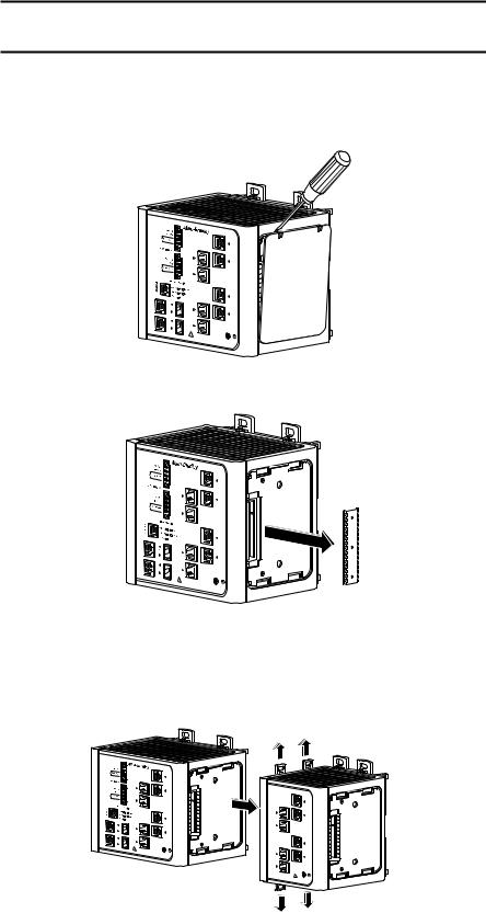
1.Remove the right side panel by firmly grasping both sides of it in the middle and pulling it outward.
If necessary, use a screwdriver to pry open the side panel.
31779-M
2. Remove the protective EMI-connector cover from the side panel.
31787-M
3.Push the upper module latches up and the lower module latches down. Then slide the switch and module together.
The expansion module is shown with the side panel removed. Do not remove this panel unless you plan to install another module.
31780-M
Rockwell Automation Publication 1783-UM003I-EN-P - March 2014 |
23 |

Chapter 1 Install the Switch
Mount the Switch on a DIN Rail
4.Push the upper and lower module latches in to secure the module to the switch.
31781-M
5.If you are installing a second module, repeat steps 1...4, but secure the second module to the right side of the first module.
IMPORTANT You cannot install an expansion module to the right of the 1783-MX08F or 1783-MX08S fiber expansion module.
WARNING: When using DIN rail mounting, additional grounding is also accomplished through the DIN rail to chassis ground. Use zinc plated yellow-chromate steel DIN rail to assist in proper grounding. The use of other DIN rail materials (for example, aluminum or plastic)) that can corrode, oxidize, or are poor conductors, can impede proper grounding. Secure DIN rail to mounting surface approximately every 200 mm (7.8 in.) using end-anchors appropriately and using a washer plate along the entire length of the DIN rail.
Follow these steps to mount the switch on a DIN rail.
1.Insert a sharp tool, such as a screwdriver, in the space next to the tab, push gently to release the catch, then turn the screwdriver to push the tab out.
31776-M
24 |
Rockwell Automation Publication 1783-UM003I-EN-P - March 2014 |
Install the Switch |
Chapter 1 |
|
|
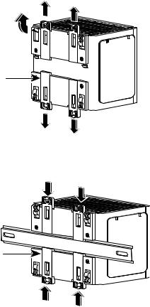
2.If you are using a heavy-duty 35 mm x 15 mm (1.38 in. x 0.59 in.) DIN rail, rotate all feet to the extended positions.
Otherwise, if you are using 35 mm x 7.5 mm (1.38 in. x 0.30 in.) DIN rail, rotate the feet to the recessed positions.
Foot
Latch
31777-M
3.Position the rear panel of the switch directly in front of the DIN rail, making sure that the DIN rail fits in the space between the two latches.
DIN Rail 
Latch
31778-M
4.Push the DIN rail latches in after the switch is over the DIN rail to secure the switch to the rail.
Rockwell Automation Publication 1783-UM003I-EN-P - March 2014 |
25 |

Chapter 1 Install the Switch
Mount the Switch on a Wall or Panel
The switch can be mounted on a wall or a panel. You need M5 or #10-24 or #10-32 bolts or screws with 1.27 cm (0.5 in.) O.D. flat washers. This hardware is not provided with the switch.
Follow these steps to mount the switch to a wall or a panel.
1.If the DIN rail latches are pushed out, push them in so they are fully locked in place.
31777-M
2.Rotate all feet to their recessed positions so that the switch can mount flat on the wall or pane.
If greater air circulation around the switch is required, rotate the feet to their extended positions before mounting the switch on the wall.
3.Position the rear panel of the switch against the wall or a panel in the desired location, as shown in this figure.
Pwr A |
(24VDC or 48 VDC) |
|
|
|
|
|
Rtn A |
|
|
Major Alarm |
|
! |
|
|
pepTloohewwicseetriurrnccciotosrmrhddoisWARNING.gchbkTteofhdoairersvecedosumnecnroevericecthtinthetghariseunnkotitwn.ooef |
|
|
Pwr B |
(24VDC or 48 VDC) |
|
|
|
|
|
Rtn B |
|
|
Minor Alarm |
|
|
Express S etup |
|
|
S ystem |
Pwr A |
|
Alarm |
Pwr B |
|
S etup |
|
|
|
|
|
1 |
|
|
2 |
|
Cisco Catalyst
1
3
4
4.Place M5 or #10-24 or #10-32 bolts or screws with 1.27 cm (0.5 in.) O.D. flat washers through each DIN rail latch, and screw them into the wall.
26 |
Rockwell Automation Publication 1783-UM003I-EN-P - March 2014 |

Install the Switch |
Chapter 1 |
|
|
Install an SFP Module (optional)
ATTENTION: Under certain conditions, viewing the small form-factor pluggable (SFP) optical transceiver may expose the eye to hazard. When viewed under some conditions, the optical port may expose the eye beyond the maximum permissible exposure recommendations.
ATTENTION: SFP modules are static sensitive devices. Always use an ESD wrist strap or similar individual grounding device when handling SFP modules.
WARNING: When you insert or remove the small form-factor pluggable (SFP) optical transceiver while power is on, an electrical arc can occur. This could cause an explosion in hazardous location installations.
IMPORTANT Using an SFP module other than those provided by Rockwell Automation will disable the switch port.
IMPORTANT Installing and removing an SFP module can shorten its useful life. Do not remove and insert SFP modules more often than is absolutely necessary.
Grasp the module on the sides, and insert it into the switch slot until you feel the connector snap into place.
31782-M
ATTENTION: If the SFP module cannot be fully inserted, stop! Do not force the module into the slot. Rotate the SFP module 180 degrees and try again.
Rockwell Automation Publication 1783-UM003I-EN-P - March 2014 |
27 |

Chapter 1 Install the Switch
Ground the Switch
ATTENTION: For proper grounding, you must always connect the power supply functional-ground screw when connecting the power supply. You must provide an acceptable grounding path for each device in your application. For more information on proper grounding guidelines, refer to publication 1770-4.1, Industrial Automation Wiring and Grounding Guidelines.
ATTENTION: You must use the external grounding screw on the front of the switch to ground the switch. Use a 5.3 mm2 (10 AWG) ground wire.
Follow these steps to connect the switch to a protective ground.
1.Use a screwdriver to remove the ground screw from the front panel of the switch.
Store the ground screw for later use.
2.If your ground wire is insulated, use a wire stripping tool to strip the
5.3 mm2 (10 AWG) ground wire to 12.7 mm (0.5 in.) ± 0.5 mm (0.02 in.).
12.7 mm (0.5 in.)
31789-M
3.Insert the ground wire into the ring terminal lug.
4.Use a crimping tool to crimp the ring terminal to the wire.
31790-M
5.Slide the ground screw through the ring terminal.
6.Insert the ground screw into the ground-screw opening on the front panel.
V |
 A RT
A RT

A |
31791-M
28 |
Rockwell Automation Publication 1783-UM003I-EN-P - March 2014 |
Install the Switch |
Chapter 1 |
|
|
Wire the DC Power Source for the Switch
7.Use a ratcheting torque screwdriver to tighten the ground screw and ring terminal lug to the switch front panel to 0.96 N•m (8.5 lb•in).
8.Attach the other end of the ground wire to a grounded bare-metal surface, such as a ground bus, or a grounded DIN rail.
WARNING: Before performing any of the following procedures, make sure that power is removed from the DC circuit or the area is nonhazardous before proceeding.
WARNING: To comply with the CE Low Voltage Directive (LVD), this equipment must be powered from a source compliant with the safety extra low voltage (SELV) or protected extra low voltage (PELV).
To comply with UL restrictions, this equipment must be powered from a source compliant with Class 2 or Limited Voltage/Current.
Follow these steps to wire DC power to the switch.
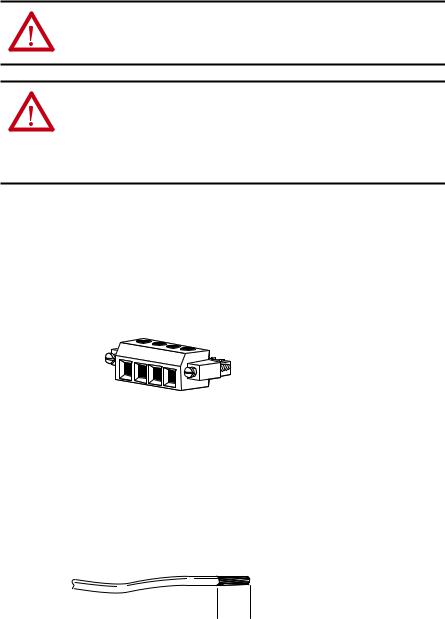
1.Locate the power and alarm relay connector and identify the positive and return DC power connections.
The positive DC power connection is labeled V, and the negative DC power connection is the adjacent connection labeled RT. Connections labeled A are used for the alarm relay connectors.
V |
RT |
A |
A |
|
|||
|
|
||
|
|
|
31783-M
2.Measure a length of 0.82…0.52 mm2 (18…20 AWG) copper wire long enough to connect to the DC power source.
3.Using an 18-gauge wire-stripping tool, strip each of the two wires to
6.3 mm (0.25 in.) ± 0.5 mm (0.02 in.).
Do not strip more than 6.8 mm (0.27 in.) of insulation from the wire. Stripping more than the recommended amount of wire can leave exposed wire from the connector after installation.

 6.8 mm (0.27 in.)
31784-M
Rockwell Automation Publication 1783-UM003I-EN-P - March 2014 |
29 |

Chapter 1 Install the Switch
4.Insert the exposed part of the positive wire into the connection labeled V and the exposed part of the return wire into the connection labeled RT.
Make sure that you cannot see any wire lead. Only wire with insulation can extend from the connector.
V |
|
RT |
V |
A |
|
A |
RT |
|
31785-M
5.Use a ratcheting-torque screwdriver to torque the power and relay
connector captive screws above the installed wire leads to 0.23 N•m
(2.0 lb•in).
6.Connect the other end of the positive wire (the one connected to V) to the positive terminal on the DC power source, and connect the other end of the return wire (the one connected to RT) to the return terminal on the DC power source.
You can use a second power source to provide redundant power. The alarm relays on the switch can be used to warn you if one of the power supplies fails. The switch operates properly with only one power source connected at either Pwr A or Pwr B.
7.If you are installing the switch and are using a second power source, repeat steps 2…6 with a second power and relay connector.
ATTENTION: If multiple power sources are used, do not exceed the specified isolation voltage.
30 |
Rockwell Automation Publication 1783-UM003I-EN-P - March 2014 |
Loading...