


 Loading...
User Manual
Stratix 6000 Ethernet Managed Switch
Catalog Numbers 1783-EMS04T, 1783-EMS08T

Important User Information
Solid-state equipment has operational characteristics differing from those of electromechanical equipment. Safety Guidelines for the Application, Installation and Maintenance of Solid State Controls (publication SGI-1.1 available from your local Rockwell Automation sales office or online at http://www.rockwellautomation.com/literature/) describes some important differences between solid-state equipment and hard-wired electromechanical devices. Because of this difference, and also because of the wide variety of uses for solid-state equipment, all persons responsible for applying this equipment must satisfy themselves that each intended application of this equipment is acceptable.
In no event will Rockwell Automation, Inc. be responsible or liable for indirect or consequential damages resulting from the use or application of this equipment.
The examples and diagrams in this manual are included solely for illustrative purposes. Because of the many variables and requirements associated with any particular installation, Rockwell Automation, Inc. cannot assume responsibility or liability for actual use based on the examples and diagrams.
No patent liability is assumed by Rockwell Automation, Inc. with respect to use of information, circuits, equipment, or software described in this manual.
Reproduction of the contents of this manual, in whole or in part, without written permission of Rockwell Automation, Inc., is prohibited.
Throughout this manual, when necessary, we use notes to make you aware of safety considerations.
WARNING: Identifies information about practices or circumstances that can cause an explosion in a hazardous environment, which may lead to personal injury or death, property damage, or economic loss.
ATTENTION: Identifies information about practices or circumstances that can lead to personal injury or death, property damage, or economic loss. Attentions help you identify a hazard, avoid a hazard, and recognize the consequence.
SHOCK HAZARD: Labels may be on or inside the equipment, for example, a drive or motor, to alert people that dangerous voltage may be present.
BURN HAZARD: Labels may be on or inside the equipment, for example, a drive or motor, to alert people that surfaces may reach dangerous temperatures.
IMPORTANT Identifies information that is critical for successful application and understanding of the product.
Allen-Bradley, Rockwell Software, Rockwell Automation, RSLinx, RSLogix, Logix5000, FLEX I/O, RSLogix 5000, Stratix 6000, and TechConnect are trademarks of Rockwell Automation, Inc.
Trademarks not belonging to Rockwell Automation are property of their respective companies.

Summary of Changes
This manual contains new and updated information. Changes throughout this revision are marked by change bars, as shown to the right of this paragraph.
Topic |
Page |
|
|
Studio 5000™ Logix Designer application is the rebranding of RSLogix™ 5000 software |
9 |
|
|
Rockwell Automation Publication 1783-UM001D-EN-P - January 2013 |
3 |

Summary of Changes
Notes:
4 |
Rockwell Automation Publication 1783-UM001D-EN-P - January 2013 |

|
Table of Contents |
|
Preface |
Studio 5000 Environment . . . . . . . . . . . . . . . . . . . . . . . . . . . . . . . . . . . . . . . . . |
. 9 |
|
Terminology. . . . . . . . . . . . . . . . . . . . . . . . . . . . . . . . . . . . . . . . . . . . . . . . . . . . . |
10 |
|
Additional Resources . . . . . . . . . . . . . . . . . . . . . . . . . . . . . . . . . . . . . . . . . . . . . |
11 |
|
Chapter 1 |
|
Basic Configuration |
Access the Home Page . . . . . . . . . . . . . . . . . . . . . . . . . . . . . . . . . . . . . . . . . . . . |
13 |
|
Access Basic Configuration Options . . . . . . . . . . . . . . . . . . . . . . . . . . . . . . . |
15 |
|
Set the IP Address. . . . . . . . . . . . . . . . . . . . . . . . . . . . . . . . . . . . . . . . . . . . . . . . |
15 |
|
Set the IP Address with BOOTP . . . . . . . . . . . . . . . . . . . . . . . . . . . . . . . . . . |
17 |
|
Set Security . . . . . . . . . . . . . . . . . . . . . . . . . . . . . . . . . . . . . . . . . . . . . . . . . . . . . . |
17 |
|
Work with Miscellaneous Settings. . . . . . . . . . . . . . . . . . . . . . . . . . . . . . . . . |
18 |
|
Status Indicators . . . . . . . . . . . . . . . . . . . . . . . . . . . . . . . . . . . . . . . . . . . . . . . . . |
20 |
|
Chapter 2 |
|
Network Services Setup |
SNMP . . . . . . . . . . . . . . . . . . . . . . . . . . . . . . . . . . . . . . . . . . . . . . . . . . . . . . . . . . |
21 |
|
Supported MIBs. . . . . . . . . . . . . . . . . . . . . . . . . . . . . . . . . . . . . . . . . . . . . . |
22 |
|
SNMP Configuration . . . . . . . . . . . . . . . . . . . . . . . . . . . . . . . . . . . . . . . . |
23 |
|
IGMP. . . . . . . . . . . . . . . . . . . . . . . . . . . . . . . . . . . . . . . . . . . . . . . . . . . . . . . . . . . |
25 |
|
IGMP Product Support. . . . . . . . . . . . . . . . . . . . . . . . . . . . . . . . . . . . . . . |
25 |
|
IGMP Querier . . . . . . . . . . . . . . . . . . . . . . . . . . . . . . . . . . . . . . . . . . . . . . . |
26 |
|
IGMP Configuration . . . . . . . . . . . . . . . . . . . . . . . . . . . . . . . . . . . . . . . . . |
27 |
|
DHCP . . . . . . . . . . . . . . . . . . . . . . . . . . . . . . . . . . . . . . . . . . . . . . . . . . . . . . . . . . |
30 |
|
Dynamic IP Address Assignment by IP Address Pool . . . . . . . . . . . . |
30 |
|
Dynamic IP Address Assignment by Port . . . . . . . . . . . . . . . . . . . . . . . |
31 |
|
DHCP Address Table . . . . . . . . . . . . . . . . . . . . . . . . . . . . . . . . . . . . . . . . . . . . |
32 |
|
MAC Address Labels . . . . . . . . . . . . . . . . . . . . . . . . . . . . . . . . . . . . . . . . . . . . . |
33 |
|
Email Configuration . . . . . . . . . . . . . . . . . . . . . . . . . . . . . . . . . . . . . . . . . . . . . |
33 |
|
SMS Configuration. . . . . . . . . . . . . . . . . . . . . . . . . . . . . . . . . . . . . . . . . . . |
35 |
|
Send Email via a Logix Controller-initiated Message Instruction . 35 |
|
|
Enter the Text of the Email Message . . . . . . . . . . . . . . . . . . . . . . . . . . . |
39 |
|
Send an SMS from the Logix Controller. . . . . . . . . . . . . . . . . . . . . . . . |
40 |
|
Modify the SMTP Server Setup in a Logix Controller Program. . . |
40 |
|
Email and SMS Error Codes. . . . . . . . . . . . . . . . . . . . . . . . . . . . . . . . . . . |
41 |
|
Chapter 3 |
|
Diagnostics |
Device Utilization. . . . . . . . . . . . . . . . . . . . . . . . . . . . . . . . . . . . . . . . . . . . . . . . |
44 |
|
RSTP Report . . . . . . . . . . . . . . . . . . . . . . . . . . . . . . . . . . . . . . . . . . . . . . . . . . . . |
45 |
|
IGMP Report. . . . . . . . . . . . . . . . . . . . . . . . . . . . . . . . . . . . . . . . . . . . . . . . . . . . |
45 |
|
MAC Address Report. . . . . . . . . . . . . . . . . . . . . . . . . . . . . . . . . . . . . . . . . . . . |
46 |
|
Alarm Setup . . . . . . . . . . . . . . . . . . . . . . . . . . . . . . . . . . . . . . . . . . . . . . . . . . . . . |
46 |
|
PLC Configuration . . . . . . . . . . . . . . . . . . . . . . . . . . . . . . . . . . . . . . . . . . . . . . |
48 |
|
Automatic Email Alerts. . . . . . . . . . . . . . . . . . . . . . . . . . . . . . . . . . . . . . . . . . . |
48 |
|
Email Queue Status . . . . . . . . . . . . . . . . . . . . . . . . . . . . . . . . . . . . . . . . . . . . . . |
50 |
|
Switch Restart . . . . . . . . . . . . . . . . . . . . . . . . . . . . . . . . . . . . . . . . . . . . . . . . . . . |
50 |
|
Display Switch Counters . . . . . . . . . . . . . . . . . . . . . . . . . . . . . . . . . . . . . . . . . |
50 |
Rockwell Automation Publication 1783-UM001D-EN-P - January 2013 |
5 |

Table of Contents |
|
|
|
Chapter 4 |
|
Switch Management |
STP/RSTP . . . . . . . . . . . . . . . . . . . . . . . . . . . . . . . . . . . . . . . . . . . . . . . . . . . . . . |
53 |
|
Spanning Tree Protocol . . . . . . . . . . . . . . . . . . . . . . . . . . . . . . . . . . . . . . . |
53 |
|
Rapid Spanning Tree Protocol . . . . . . . . . . . . . . . . . . . . . . . . . . . . . . . . . |
54 |
|
STP/RSTP Configuration . . . . . . . . . . . . . . . . . . . . . . . . . . . . . . . . . . . . |
55 |
|
VLAN Configuration. . . . . . . . . . . . . . . . . . . . . . . . . . . . . . . . . . . . . . . . . . . . . |
57 |
|
Port Configuration . . . . . . . . . . . . . . . . . . . . . . . . . . . . . . . . . . . . . . . . . . . . . . . |
59 |
|
Mirror Configuration. . . . . . . . . . . . . . . . . . . . . . . . . . . . . . . . . . . . . . . . . . . . . |
61 |
|
MAC ID Management . . . . . . . . . . . . . . . . . . . . . . . . . . . . . . . . . . . . . . . . . . . |
63 |
|
Port Segmenting . . . . . . . . . . . . . . . . . . . . . . . . . . . . . . . . . . . . . . . . . . . . . . . . . |
64 |
|
QoS Setup . . . . . . . . . . . . . . . . . . . . . . . . . . . . . . . . . . . . . . . . . . . . . . . . . . . . . . . |
65 |
|
Appendix A |
|
Upgrade Firmware |
Upgrade with the Web Management Interface . . . . . . . . . . . . . . . . . . . . . . |
67 |
|
Appendix B |
|
User Name and Password Rules |
User Name and Password Characters . . . . . . . . . . . . . . . . . . . . . . . . . . . . . . |
69 |
|
Other Rules. . . . . . . . . . . . . . . . . . . . . . . . . . . . . . . . . . . . . . . . . . . . . . . . . . . . . . |
69 |
|
Appendix C |
|
Factory Reset |
Access the Reset Button. . . . . . . . . . . . . . . . . . . . . . . . . . . . . . . . . . . . . . . . . . . |
71 |
|
Reset IP Address . . . . . . . . . . . . . . . . . . . . . . . . . . . . . . . . . . . . . . . . . . . . . . . . . |
72 |
|
Change Settings to Default. . . . . . . . . . . . . . . . . . . . . . . . . . . . . . . . . . . . . . . . |
72 |
|
Appendix D |
|
Data Layout |
DINT Input . . . . . . . . . . . . . . . . . . . . . . . . . . . . . . . . . . . . . . . . . . . . . . . . . . . . . |
73 |
|
DINT Output . . . . . . . . . . . . . . . . . . . . . . . . . . . . . . . . . . . . . . . . . . . . . . . . . . . |
74 |
|
Appendix E |
|
Add the Switch to Software |
Generic Profile . . . . . . . . . . . . . . . . . . . . . . . . . . . . . . . . . . . . . . . . . . . . . . . . . . . |
75 |
|
Add-on Profile . . . . . . . . . . . . . . . . . . . . . . . . . . . . . . . . . . . . . . . . . . . . . . . . . . . |
77 |
|
Enter General Information . . . . . . . . . . . . . . . . . . . . . . . . . . . . . . . . . . . . |
78 |
|
Enter Connection Information . . . . . . . . . . . . . . . . . . . . . . . . . . . . . . . . |
79 |
|
View Identification and Status Information. . . . . . . . . . . . . . . . . . . . . |
80 |
|
Configure Network and Port Settings . . . . . . . . . . . . . . . . . . . . . . . . . . |
80 |
|
View Port Diagnostic Information . . . . . . . . . . . . . . . . . . . . . . . . . . . . . |
82 |
|
Configure IGMP . . . . . . . . . . . . . . . . . . . . . . . . . . . . . . . . . . . . . . . . . . . . . |
83 |
|
Configure DHCP . . . . . . . . . . . . . . . . . . . . . . . . . . . . . . . . . . . . . . . . . . . . |
84 |
|
Configure Bandwidth and MAC ID Management Alarming . . . . . |
85 |
|
Configure Port Behavior for Fault and Idle States . . . . . . . . . . . . . . . |
85 |
6 |
Rockwell Automation Publication 1783-UM001D-EN-P - January 2013 |

|
|
Table of Contents |
|
Appendix F |
|
Download or Upload a Configuration |
Upload Configuration. . . . . . . . . . . . . . . . . . . . . . . . . . . . . . . . . . . . |
. . . . . . . . 87 |
|
Download Configuration . . . . . . . . . . . . . . . . . . . . . . . . . . . . . . . . . . |
. . . . . . . 87 |
|
Appendix G |
|
Available SFP Modules and Cables |
Available SFP Modules . . . . . . . . . . . . . . . . . . . . . . . . . . . . . . . . . . . . |
. . . . . . . 89 |
|
SFP Module Cable Specifications. . . . . . . . . . . . . . . . . . . . . . . . . . . |
. . . . . . . 89 |
Index |
|
|
Rockwell Automation Publication 1783-UM001D-EN-P - January 2013 |
7 |

Table of Contents
Notes:
8 |
Rockwell Automation Publication 1783-UM001D-EN-P - January 2013 |

Preface
|
This manual is intended for users of the switch. We assume you are familiar with |
|
the procedures in the Stratix 6000™ Ethernet Managed Switch Installation |
|
Instructions, publication 1783-IN004. |
|
Read and understand this manual before using the products. Consult your |
|
Rockwell Automation representative if you have any questions or comments. |
|
For information about the features supported in your firmware revision, refer to |
|
the firmware release notes, publication 1783-RN003. |
Studio 5000 Environment |
The Studio 5000™ Engineering and Design Environment combines engineering |
|
and design elements into a common environment. The first element in the |
|
Studio 5000 environment is the Logix Designer application. The Logix Designer |
|
application is the rebranding of RSLogix™ 5000 software and will continue to be |
|
the product to program Logix5000™ controllers for discrete, process, batch, |
|
motion, safety, and drive-based solutions. |
The Studio 5000 environment is the foundation for the future of Rockwell Automation® engineering design tools and capabilities. It is the one place for design engineers to develop all of the elements of their control system.
Rockwell Automation Publication 1783-UM001D-EN-P - January 2013 |
9 |

Preface
Terminology |
Refer to this table for terms used in this publication. |
Table 1 - Managed Switch Terminology |
|
|
|
Term |
Description |
|
|
1783-EMS |
All references to 1783-EMS in this manual refer to catalog numbers 1783-EMS04T and 1783-EMS08T. |
|
|
Auto-MDIX |
Automatic Medium-dependent Interface Crossover. |
|
Allows the switch to detect the required cable type (straight-through or crossover) for copper Ethernet connections and configures the interfaces |
|
accordingly. |
|
|
BOOTP |
Commonly used with Allen-Bradley Ethernet products, the BOOTP protocol is used by a client machine to locate its IP address and network mask. |
|
|
DHCP |
Dynamic Host Configuration Protocol. |
|
A network protocol that is used to configure devices, so that they can communicate on an IP network. A client machine uses this protocol to acquire |
|
configuration information, such as an IP address and default gateway, from a server running the protocol. The client then uses this information to |
|
configure itself. |
|
|
DNS |
Domain Name Server. |
|
Translates domain names into IP addresses, for example, www.example.com can translate to 192.168.100.100. |
|
|
Domain |
A group of computers and devices on a network that are controlled as a unit with common rules and procedures. |
|
|
IGMP |
Internet Group Management Protocol. |
|
A protocol that manages how adapters and other components join and leave multicast groups. IGMP snooping is a feature of IGMP that allows Ethernet |
|
switches to look (snoop) inside packets to determine which destinations really need to receive the data. |
|
|
QoS |
Quality of service. |
|
A method of managing network resources through the classification of Ethernet traffic into high and low priority queues. |
|
|
SMS |
Short Message Service. |
|
A communication service that allows text messaging between mobile phones. |
|
|
SNMP |
Simple Network Management Protocol. |
|
A protocol that exchanges messages with devices on a network for the purpose of monitoring the devices.SNMP enables a switch to be remotely |
|
managed through other network management software. |
|
|
Spanning Tree |
Refers to Rapid Spanning Tree Protocol (RSTP) or Spanning Tree Protocol (STP). |
|
Used with network topologies that provide more than one physical path between two devices, spanning tree protocol manages path redundancies |
|
while preventing undesirable loops in the network. If a fault should occur on an active port, the switch will begin transmitting out one of the blocked |
|
ports. |
|
|
TCP |
Transmission Control Protocol. |
|
TCP enables two hosts to establish a connection and exchange streams of data. |
|
TCP guarantees delivery of data and also guarantees that packets are delivered in the same order in which they were sent. |
|
|
UDP |
User Datagram Protocol. |
|
This protocol offers a minimal transport service. UDP is used by applications that do not require the level of service of TCP or use communication |
|
services (for example, multicast or broadcast delivery) not available from TCP. |
|
An application program running over UDP must deal directly with end-to-end communication anomalies that a connection-oriented protocol would |
|
have handled - for example, retransmission for reliable delivery, packetization and reassembly, flow control, and congestion avoidance, when these are |
|
required. |
|
This is commonly seen with I/O type devices that send out information at an RPI rate. |
|
|
VLAN |
Virtual local-area network. |
|
A logical segment of network users and resources grouped by function, team, or application. This segmentation is without regard to the physical |
|
location of the users and resources. |
|
|
10 |
Rockwell Automation Publication 1783-UM001D-EN-P - January 2013 |
Preface
Additional Resources
These documents contain additional information concerning related products from Rockwell Automation.
Resource |
Description |
|
|
|
|
|
|
Stratix Ethernet Switch Specifications, publication |
Provides technical specifications for Stratix Ethernet switches. |
|
|
|
|
||
1783-TD001 |
|
|
|
|
|
|
|
Stratix 6000 Ethernet Managed Switch Installation |
Provides detailed specifications and information related to |
|
|
Instructions, publication 1783-IN004 |
installation of the switch. |
|
|
|
|
|
|
Industrial Automation Wiring and Grounding |
Provides general guidelines for installing a Rockwell Automation |
|
|
Guidelines, publication 1770-4.1 |
industrial system. |
|
|
|
|
|
|
Product Certifications website, http://www.ab.com |
Provides declarations of conformity, certificates, and other |
|
|
|
certification details. |
|
|
|
|
|
|
Internet Engineering Task Force website, |
Provides access to documents such as the RFC (request for |
|
|
http://www.ietf.org |
comment), public documents on networking topics and |
|
|
|
protocols, Internet standards documents, best current-practices |
|
|
|
information, and related informational documents. |
|
|
|
|
|
|
You can view or download publications at http://www.rockwellautomation.com/literature/. To order paper copies of technical documentation, contact your local Allen-Bradley distributor or Rockwell Automation sales representative.
Rockwell Automation Publication 1783-UM001D-EN-P - January 2013 |
11 |

Preface
Notes:
12 |
Rockwell Automation Publication 1783-UM001D-EN-P - January 2013 |

Chapter 1
Basic Configuration
Access the Home Page
This chapter covers how to access the switch’s web interface home page. It also includes information about how to set an IP address and security, work with miscellaneous options, and understand status indicators.
Use these steps to access the web interface home page for the switch.
IMPORTANT |
Before connecting to the network, set the IP address of the switch as |
|
described in Set the IP Address. |
|
|
1.Connect the switch to your computer’s LAN card.
This connection is required before you can access the home page. For information about how to establish this connection, see the Stratix 6000 Ethernet Managed Switch Installation Instructions, publication 1783-IN004.
2.Open your web browser once the connection is established.
3.In the address bar of your web browser, type your switch's IP address. For example, to use the default IP address, type http://192.168.1.1.
4.From the user name and password dialog box, leave the user name empty and type the following case-sensitive password: PASSWORD
If the web browser does not open, verify this information:
•The IP address of the switch. The default IP address is 192.168.1.1.
•Your connection setup. Refer to the Stratix 6000 Ethernet Managed Switch Installation Instructions, publication 1783-IN004.
•Whether the switch has power. The green power-status indicator should be on.
•Whether the cable is connected. A green or yellow status indicator should be lit on the Ethernet port.
•A proxy server is not preventing you from accessing the switch.
5.When the home page appears, refer to Table 2 for information about the items on the page.
Rockwell Automation Publication 1783-UM001D-EN-P - January 2013 |
13 |

Chapter 1 Basic Configuration
Table 2 - Items on the Home Page
Value |
Description |
|
|
Device Name |
You provide this entry to identify the switch. See page 18 for instructions on entering the switch’s name. |
|
|
Spanning Tree |
Indicates the current Rapid Spanning Tree Protocol (RSTP) mode of the switch. Possible values are Enabled (RSTP), Enabled (STP |
|
Compatibility), or Disabled. For more about setting the RSTP mode, see page 55. |
|
|
VLAN 802.1Q |
Indicates whether the virtual local-area network (VLAN) feature is enabled on the switch, as described on page 57. Note that the VLAN |
|
feature used in earlier firmware revisions has been renamed port segmenting. As of firmware revisions 0.11 and 0.53, a new VLAN |
|
feature is provided for only the 1783-EMS08T switch. |
|
|
IGMP Snooping |
Filtering mechanism for multicast traffic should be used when I/O is running on the Ethernet network. For more about IGMP snooping, |
|
see page 25. |
|
|
Port Mirroring |
Allows traffic on one port to be copied and sent (mirrored) to another port so that an Ethernet protocol analyzer can capture it. For more |
|
about port mirroring, see page 61. |
|
|
QoS |
When enabled, the switch can prioritize packet delivery to a certain port or MAC address. For more about QoS, see page 65. |
|
|
MAC ID Management |
Determines if a MAC ID is authorized on the network by checking the allowed MAC IDs and notifies the switch’s controller when an |
|
unauthorized node appears on the network. For more about MAC ID management, see page 63. |
|
|
Product Type |
Shows the part number of the switch. |
|
|
Serial Number |
Unique to every switch. |
|
|
MAC Address |
Indicates the Ethernet address of the switch. |
|
|
Firmware Revision |
Check our website to make sure you are up to date. |
|
This file updates product firmware. The web interface must be updated separately. |
|
|
Web Revision |
Check our website to make sure you are up to date. |
|
This file updates your web interface. For related information, see Appendix A. |
|
|
Uptime |
This setting indicates the switch’s running time. This timer is reset when the switch is powered up. |
|
|
Link (Port Status) |
Possible values are ON and OFF. |
|
ON is if a device is connected to the port and has power. ON corresponds to the Link State Status indicator on the switch port being either |
|
solid or flashing green. |
|
|
14 |
Rockwell Automation Publication 1783-UM001D-EN-P - January 2013 |

Basic Configuration |
Chapter 1 |
|
|
Table 2 - Items on the Home Page (continued)
Value |
Description |
|
|
VLAN (Port Status) |
If virtual local-area network (VLAN) is enabled on the switch, the VLAN column indicates the VLAN ID assigned to each port. If the port is |
|
assigned the role of a switch or router, the VLAN column displays the word ‘trunk’. |
|
For more about VLAN configuration, see page 57. |
|
|
Speed (Port Status) |
Possible values are 10 or 100 signifying a 10 Mbps or 100 Mbps connection. |
|
This corresponds to the Data Rate status indicator on the switch port being off (10 Mbps) or solid amber (100 Mbps). |
|
|
Duplex (Port Status) |
Possible values are Full and Half. |
|
|
Gigabit Port Information |
This is offered as an option to the 1783-EMS08T switch and requires a pluggable SFP MSA-compliant transceiver that you must purchase |
|
separately. |
|
A fiber optic transceiver can be used to connect to a fiber optic network. |
|
Information about the transceiver used and the connection speed are found on the home page. |
|
|
Resources |
Provides links to our website and this manual (you have to be connected to the Internet to reach our website). |
|
The manual link in this section does not require an Internet connection because it is embedded in the product. |
|
For convenience, we have also embedded the EDS file for this device under the EDS file link in this section. Download and install it with |
|
the EDS hardware installation tool (one of the RSLinx® tools). |
|
|
Contacts |
Displays contact information entered on the Miscellaneous tab, as described on page 18. |
|
This lets you enter a name or phone number and email address of the appropriate contact person. |
|
|
Access Basic Configuration
Options
From the home page, click the Basic Configuration folder to expand the menu bar in the left pane to show these tabs:
•Network Configuration
•Set Security
•Miscellaneous
Set the IP Address
You normally need to change your IP address to install the switch into your Ethernet network.
Use these steps to change the IP address.
1.Find an available IP address on your subnet.
2.Connect the switch to your computer’s LAN card.
For additional information, refer to the Stratix 6000 Ethernet Managed Switch Installation Instructions, publication 1783-IN004.
3.From the navigation pane, expand the Basic Configuration folder and select Network Configuration to display the Network Configuration tab.
Rockwell Automation Publication 1783-UM001D-EN-P - January 2013 |
15 |

Chapter 1 Basic Configuration
4.Type your new IP address.
5.Change the subnet mask and default gateway, if needed.
6.Turn off BOOTP Client to prevent dynamic IP address assignment.
If using host names on the network, Name Resolution must be turned on and the DNS server addresses must be configured (usually required if using the email function).
7.Click Apply Changes to change the IP and subnet.
IMPORTANT |
The switch does not load the new IP and subnet address until |
|
power is cycled. |
|
|
8.Cycle power.
Once the IP and subnet are changed, you must cycle power to load the new address. Power can be cycled remotely through the management interface by expanding the Diagnostics folder and clicking Controller Restart. This restarts the 1783-EMS switch and does not restart the controller. All communication through the switch is interrupted.
16 |
Rockwell Automation Publication 1783-UM001D-EN-P - January 2013 |
Basic Configuration |
Chapter 1 |
|
|
Set the IP Address with BOOTP
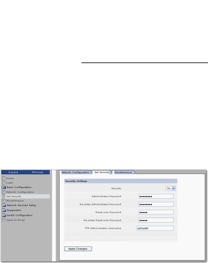
Set Security
The 1783-EMS switch ships with the BOOTP client enabled by default. To assign an address, use this procedure.
1.Put the switch on a network with a BOOTP server.
2.Cycle power to the switch.
The 1783-EMS switch attempts to obtain an IP address several times from the server before timing out and defaulting to the factory preset address of 192.168.1.1.
IMPORTANT |
The MAC address of the switch is on the home page. |
|
192.168.1.1 could interfere with another device on the network. |
|
|
We recommend changing the administrator and read-only password before you place the switch in service.
The administrator password is used for the management interface (HTTP session), Telnet, and the FTP interface (used to upgrade the firmware). The user name is verified for the FTP session only. The user name for the HTTP session is not checked (therefore can be anything). The read-only password is used for read-only access to the management interface (HTTP session).
Use these steps to change your administrative or read-only user name and password.
1.From the navigation pane, expand the Basic Configuration folder and select Set Security to display the Set Security tab.
Rockwell Automation Publication 1783-UM001D-EN-P - January 2013 |
17 |

Chapter 1 Basic Configuration
Work with Miscellaneous Settings
2.Change the user name and password. See Appendix B for recommendations.
3.Click Apply Changes.
4.Cycle power to the switch to load the new user name and password.
The administrative password applies to Telnet, FTP, and the web browser interface.
IMPORTANT |
The 1783-EMS switch does not load the new settings until power is |
|
cycled. |
|
|
Use these steps to configure miscellaneous switch settings.
1.From the navigation pane, expand the Basic Configuration folder and select Miscellaneous to display the Miscellaneous tab.
2.Use the information in Table 3 to configure the settings.
3.Click Apply Changes.
18 |
Rockwell Automation Publication 1783-UM001D-EN-P - January 2013 |

Basic Configuration Chapter 1
Table 3 - Miscellaneous Switch Settings
Setting |
Description |
|
|
|
|
Box Name |
Lets you give your 1783-EMS switch a name that describes its location or connected devices. This feature is useful when multiple 1783-EMS |
|
|
switches are installed. The switch reports this name on the home page. To change this setting, complete this procedure. |
|
|
1. |
Click Basic Configuration. |
|
2. |
Click Miscellaneous. |
|
3. |
Type the new name in the text box and click Apply Changes. |
|
|
The new name does not show in the home page until you click Refresh on the browser. |
|
|
|
Minutes of User Inactivity |
Lets you change the length of time the management interface (HTTP session) remains open while inactive. Choose from 0…99 min. Select |
|
|
0 = Feature Disabled for the interface to remain open until it is closed. The default is 3 min. |
|
|
|
|
Seconds Between Refresh |
Controls the refresh rate of the management interface. |
|
|
• |
Valid values are 0…99 seconds |
|
• |
0 = Feature disabled for no refresh |
|
• |
Default value is 5 seconds |
|
|
|
Contact Info, Contact Email |
Use to identify the responsible service personnel. |
|
|
|
|
Rockwell Automation Publication 1783-UM001D-EN-P - January 2013 |
19 |
Chapter 1 Basic Configuration
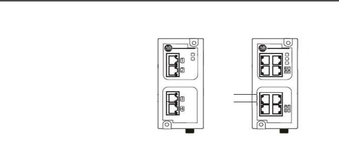
Status Indicators
The figures and table show the status indicators.
1783-EMS04T |
1783-EMS08T |
||||||
|
|
|
3 |
|
|
3 |
|
|
|
4 |
|
|
4 |
||
|
|
|
|||||
|
|
|
|
|
|
|
5 |
|
|
|
|
|
|
||
1 |
|
|
|
1 |
|
|
|
||
2 |
|
|
2 |
|
|
||||
Item |
Indicator |
State |
Description |
|
|
|
|
1 |
Link state(1) |
Solid green |
Ethernet link exists. |
|
|
Flashing green |
Valid link is present and transmitting data. |
|
|
|
|
2 |
Data rate(1) |
Solid amber |
100 Mbit link is present. |
|
|
Off |
10 Mbit link is present. |
|
|
|
|
3 |
PWR |
Solid green |
Power to the switch is present. |
|
|
|
|
4 |
STA |
Flashing green |
This heartbeat indicator normally flashes at a slow rate. |
|
|
|
It flashes at a faster rate when the switch is being upgraded |
|
|
|
or set back to factory default settings by using the button |
|
|
|
on the back of the switch. |
|
|
|
|
5 |
UPL |
Solid green |
Fiber transceiver present. |
|
|
|
|
|
|
Flashing green |
Flashing indicates data is being transmitted over the |
|
|
|
gigabit link on the 1783-EMS08T switch that has a gigabit |
|
|
|
fiber transceiver on the bottom of the switch. |
|
|
|
|
(1) Appears on all copper Ethernet ports.
20 |
Rockwell Automation Publication 1783-UM001D-EN-P - January 2013 |
Chapter 2
Network Services Setup
SNMP
This chapter covers information related to network services setup using the switch’s web interface, including how to configure these protocols:
•Simple Network Management Protocol (SNMP)
•Internet Group Management Protocol (IGMP)
•Dynamic Host Configuration Protocol (DHCP)
For information about how to access the web interface for the switch, refer to Chapter 1.
Simple Network Management Protocol (SNMP) specifies the diagnostic data that a host computer must maintain for network management software. Hosts typically keep statistics on the status of their network interfaces, incoming and outgoing traffic, dropped datagrams, and error messages generated. Network management protocols let network management software access these statistics.
SNMP is based on three concepts:
•SNMP managers, also known as client software or SNMP browsers
•SNMP agents, also known as network devices or SNMP servers
•Management Information Base (MIB)
The SNMP manager runs SNMP management software. Network devices to be managed, such as bridges, routers, servers, and workstations, have an agent software module. The agent provides access to a local MIB of objects that reflects the resources and activity of the device. The agent also responds to manager commands to retrieve values from the MIB. The agent and the MIB are on the switch. To configure SNMP on the switch, you define the relationship between the manager and the agent.
The Stratix 6000 switch supports SNMP versions 1 and 2.
•SNMP versions 1 and 2 are generally used for network monitoring without network control.
•The supported versions use a community-based form of security. SNMP managers can access the agent MIB through passwords referred to as community names.
•The Stratix 6000 switch automatically recognizes the SNMP version from an incoming request, but you must manually set the version for SNMP trap destinations, as described on page 24.
Rockwell Automation Publication 1783-UM001D-EN-P - January 2013 |
21 |

Chapter 2 Network Services Setup
Supported MIBs
The Stratix 6000 switch supports the MIBs listed below.
•MIB-II—The published definition of MIB-II has been modified for the Stratix 6000 switch, as described in MIB-II Modifications below. For a detailed definition of MIB-II, refer to RFC 1213 at http://www.ietf.org/ rfc/rfc1213.txt.
•ETHERLIKE-MIB—For a detailed definition, refer to RFC 1643 at http://tools.ietf.org/html/rfc1643.
•RMON-MIB—The Stratix 6000 supports only the Ethernet Statistics Group in the RMON-MIB. For a detailed definition, refer to RFC 2819 at http://tools.ietf.org/html/rfc2819.
MIB-II Modifications
Standard read-write access has been changed to read-only access for the MIB-II variables listed below.
interface.ifTable.ifEntry.ifAdminStatus
(Fixed value—device is UP)
at.atTable.atEntry.atIfIndex
at.atTable.atEntry.atPhysAddress
at.atTable.atEntry.atNetAddress
(The ARP cache table cannot be modified)
ip.ipForwarding (Fixed value, not-forwarding, not acting as a gateway) ip.ipDefaultTTL (Fixed value IP_DTTL - 60s)
ip.ipRouteTable.ipRouteEntry.ipRouteDest
ip.ipRouteTable.ipRouteEntry.ipRouteIfIndex
ip.ipRouteTable.ipRouteEntry.ipRouteMetric1
ip.ipRouteTable.ipRouteEntry.ipRouteMetric2
ip.ipRouteTable.ipRouteEntry.ipRouteMetric3
ip.ipRouteTable.ipRouteEntry.ipRouteMetric4
ip.ipRouteTable.ipRouteEntry.ipRouteNextHop
ip.ipRouteTable.ipRouteEntry.ipRouteType
ip.ipRouteTable.ipRouteEntry.ipRouteAge
ip.ipRouteTable.ipRouteEntry.ipRouteMask
ip.ipRouteTable.ipRouteEntry.ipRouteMetric5
(A routing entry cannot be added via SNMP)
22 |
Rockwell Automation Publication 1783-UM001D-EN-P - January 2013 |

Network Services Setup |
Chapter 2 |
|
|
ip.ipNetToMediaTable.ipNetToMediaEntry.ipNetToMediaIfIndex
ip.ipNetToMediaTable.ipNetToMediaEntry.ipNetToMediaPhysAddress
ip.ipNetToMediaTable.ipNetToMediaEntry.ipNetToMediaIpAddress
ip.ipNetToMediaTable.ipNetToMediaEntry.ipNetToMediaType
(A static entry cannot be added into the ARP cache table)
tcp.tcpConnTable.tcpConnEntry.tcpConnState
(An established or pending TCP connection cannot be reset)
SNMP Configuration
Enable SNMP if you want to run SNMP on your network. SNMP is disabled by default.
Before configuring SNMP settings, understand these concepts:
•Community names—Community names are passwords to the switch Management Information Base (MIB) that allow a remote manager readonly or read-write access to the switch. The Stratix 6000 switch supports one read-only community name and one read-write community name. You can change the default names.
•SNMP traps—SNMP traps are unsoliticited messages sent to a remote manager from an agent. Traps are an efficient way to inform managers that are connected to a large number of devices with many objects. By providing unsolicited messaging, traps can reduce SNMP polling by a manager. The Stratix 6000 switch supports two destination traps that can be enabled or disabled. By default, both traps are disabled.
Use these steps to configure SNMP.
1.From the navigation pane, expand the Network Services Setup folder and select SNMP Configuration.
Rockwell Automation Publication 1783-UM001D-EN-P - January 2013 |
23 |

Chapter 2 Network Services Setup
2.From the SNMP Enabled pull-down menu, choose Enabled to use SNMP.
3.Change the deault case-sensitive community names if desired.
•The read-only community enables the switch to validate Get (readonly) requests from a network management station. If you set the SNMP read community, users can access MIB objects, but cannot change them.
•The read-write community enables the switch to validate Set (readwrite) requests from a network management station.
4.In the System Info area, provide optional information about the switch for informational purposes only.
a. In the Location field, type the physical location of the switch, such as the building where the switch is locatd.
b. In the Contact field, type the switch name or network administrator.
5.Identify up to two trap destinations by completing the fields below.
Trap Destination Field |
Description |
|
|
Enabled |
Check to enable trap messages to be sent. |
|
|
IP Address |
Type the IP address of the SNMP trap recipient. |
|
|
Port |
Type the UDP port number to which traps will be sent. |
|
The default port number is 162. |
|
|
Community |
Type the read-only or read-write SNMP community name to be used in |
|
traps sent to the destination. |
|
Community names are case-sensitive. |
|
|
SNMP Version |
Choose the SNMP version to use. |
|
|
6.Click Apply Changes.
The changes will take effect immediately without requiring you to cycle power to the switch.
24 |
Rockwell Automation Publication 1783-UM001D-EN-P - January 2013 |

Network Services Setup |
Chapter 2 |
|
|
IGMP
Internet Group Management Protocol (IGMP) snooping sorts multicasting devices into groups. This limits the multicast packets received by hosts that do not need the information and makes the network more efficient and deterministic.
Option |
Description |
Broadcast |
Without IGMP snooping, an I/O module acts like a broadcasting device and all |
|
devices on the subnet are flooded with I/O traffic. |
Multicast |
IGMP snooping filters the I/O traffic from devices that are not in the intended |
|
multicast group. |
Unicast |
A message instruction from one Logix controller to another is an example of |
|
unicast; it contains one source and one destination address. |
By default, IGMP is disabled. Enable IGMP snooping when I/O is running on your network. IGMP helps to isolate this UDP traffic to ports that need to receive it. When it is not used, other devices may be slowed down by the continuous flow of UDP packets.
IGMP Product Support
Rockwell Automation products support IGMP, version 2.
When using the Logix Designer application to configure your switch, consider the following:
•Settings on the IGMP page in the Add-on Profile overwrite settings made on the web management interface.
•If you are scanning the 1783-EMS switch with the Logix Designer application, use the IGMP page in the Add-on Profile to configure IGMP to avoid confusion. See Appendix E for more information.
The switch manages a report of IGMP information, including multicast groups, querier information, and IGMP states per virtual local-area network (VLAN). The report is available through the web interface. For more information about this report, refer to IGMP Report on page 45.
Rockwell Automation Publication 1783-UM001D-EN-P - January 2013 |
25 |

Chapter 2 Network Services Setup
IGMP Querier
The IGMP querier function can be enabled to query your network for group information at a specified time interval. The configuration options available for IGMP querier depend on whether VLANs are enabled on your network.
•If you plan to use VLANs on your network, the IGMP querier function can be enabled for only one VLAN per switch. The IP address of the querier may be different on each VLAN.
You can choose to assign the querier to the management VLAN or a custom VLAN. The querier is assigned to the management VLAN by default.
–If the querier is assigned to the management VLAN, the querier IP address is the IP address defined on the Network Configuration tab, as described in Set the IP Address on page 15.
–If you want to assign the querier to a custom VLAN, you must first set up the custom VLAN on the VLAN Configuration tab, as described in VLAN Configuration on page 57. Assigning the querier to a custom VLAN requires you to know which IP address you want to assign to the querier.
•If you do not plan to use VLANs on your network, you can enable or disable a single querier instance on the network. The querier function is enabled by default. If more than one querier instance is detected on the network, only the querier with the lowest IP address is active. All other queriers are silent.
26 |
Rockwell Automation Publication 1783-UM001D-EN-P - January 2013 |

Network Services Setup |
Chapter 2 |
|
|
IGMP Configuration
Use these steps to configure IGMP.
1.From the navigation pane, expand the Network Services Setup folder and select IGMP Configuration.
2.From the IGMP Snooping pull-down menu, choose Enabled to use IGMP snooping.
When you enable IGMP snooping, additional configuration options appear on the screen.
3.From the IGMP Version menu, choose version 1 or 2.
Version 2 is the default when IGMP snooping is enabled and is the recommended setting. Per the IGMP definition, hosts and routers implementing differing IGMP versions will interoperate correctly on the network.
Rockwell Automation Publication 1783-UM001D-EN-P - January 2013 |
27 |
Chapter 2 Network Services Setup
4.If VLAN is not enabled on the switch, choose to enable or disable the IGMP querier function from the Querier Mode pull-down menu.
or
If VLAN is enabled on the switch, choose one of these options from the Querier Mode pull-down menu:
•Disabled—The IGMP querier function is disabled on all VLANs.
•Enabled on Management VLAN—The IGMP querier function is enabled and assigned to the management VLAN only. This is the default setting. For more information about setting up the management VLAN, refer to VLAN Configuration on page 57.
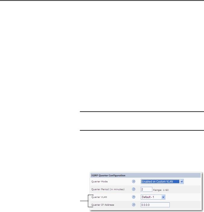
•Enabled on Custom VLAN—The IGMP querier function is enabled and assigned to a custom VLAN. If you choose this option, you must also specify the querier VLAN and IP address as described in step 6.
5.In the Querier Period field, specify a time interval in minutes, 1…60, to determine how often your network is queried for group information.
The default querier period is 2 minutes.
IMPORTANT Specify the same number of minutes on all switches in the network. The querier period must be specified even if the querier function is disabled.
6.If you chose the Enabled on Custom VLAN querier mode, complete the fields described below.
•Querier VLAN—Choose the custom VLAN to which to assign the querier.
•Querier IP Address—Type the IP address of the querier running on the custom VLAN.
Additional fields appear when you choose the Enabled on Custom VLAN querier mode.
28 |
Rockwell Automation Publication 1783-UM001D-EN-P - January 2013 |

Network Services Setup |
Chapter 2 |
|
|
7.In the Router Ports Configuration area, choose the methods to use for detecting when a multicast router is connected to a switch port.
When a multicast router, including IGMP querier, is connected to a switch port, all multicast packets and IGMP reports are forwarded on that port. This behavior is important for the proper functioning of IGMP snooping.
You can enable one or both of the following options:
•Autodetect—Accept the default setting of Enabled if you want the switch to automatically determine whether an end station or multicast router is connected to its ports. To determine which type of device is connected to a port, the switch uses Cisco Discovery Protocol (CDP) or Multicast Router Discovery (MRD).
•Manual—Enable this setting if you need to connect a switch from a different vendor that does not support CDP or MRD protocols. When
you enable the Manual setting, a series of checkboxes appears, so you can specify which ports will be connected to a router that does not support CDP or MRD protocols.
8.From the Multicast Packets Forwarding pull-down menu, choose where to forward multicast packets.
•To Listeners Only—The switch forwards multicast packets to ports in the Listening state only.
•To Listeners and Uplink Port—The switch forwards multicast packets to ports in the Listening state and the uplink port. This is the default setting.
TIP |
This setting is useful if you need to route multicast packets between |
|
two networks. |
•To Listeners and All Snooper Ports (Standard)—The switch forwards multicast packets to ports in the Listening state and to all multicast routers, or snoopers. Use this setting if you want multicast traffic to be filtered only on ports where end stations are connected and not between switches.
9.From the Uplink Port pull-down menu, choose Autodetect (Querier) if you want the Stratix 6000 switch to automatically determine the uplink port. Otherwise, set the uplink port manually by choosing a specific port.
10.Click Apply Changes.
The changes will take effect immediately without requiring you to cycle power to the switch.
Rockwell Automation Publication 1783-UM001D-EN-P - January 2013 |
29 |
Loading...