


C N E
u
Important User Information
Because of the variety of uses for the products described in this publication, those responsible for the application and use of this control equipment must satisfy themselves that all necessary steps have been taken to assure that each application and use meets all performance and safety requirements, including any applicable laws, regulations, codes
and standards.
The illustrations, charts, sample programs and layout examples shown in this guide are intended solely for example. Since there are many variables and requirements associated with any particular installation, Allen-Bradley does not assume responsibility or liability (to include intellectual property liability) for actual use based upon the examples shown in this publication.
Allen-Bradley publication SGI-1.1, ªSafety Guidelines For The Application, Installation and Maintenance of Solid State Controlº (available from your local Allen-Bradley office) describes some important differences between solid-state equipment and electromechanical devices which should be taken into consideration when applying products such as those described in this publication.
Reproduction of the contents of this copyrighted publication, in whole or in part, without written permission of Allen-Bradley Company, Inc.
is prohibited.
Throughout this manual we make notes to alert you to possible injury to people or damage to equipment under specific circumstances.
ATTENTION: Identifies information about practices or circumstances that can lead to personal injury or death, property damage or economic loss.
Attention helps you:
Identify a hazard.
Avoid the hazard.
Recognize the consequences.
Important: Identifies information that is especially important for successful application and understanding of the product.
Important: We recommend you frequently backup your application programs on appropriate storage medium to avoid possible data loss.

mm n s
mm n s
Summary of Changes
This release of the publication contains updated information from the last release.
Updated Information
This publication covers the Series B version of the Analog Output module.In addition, this version of the manual contains information formally included in publication 1771-6.5.30±RN1, dated December 1995.
A revised circuit board layout has the configuration jumpers relocated from previous versions. Access holes are included in the side cover so that covers no longer have to be removed to adjust the jumpers or potentiometers.
The module also contains information on ªCompliance to European Union Directives.º
Change Bars
To help you find new and updated information in this release of the publication, we have included change bars as shown to the right of this paragraph.
P 77 8

SOC-2 Summary of Changes
P 77 8

Preface
Preface
Manual's Purpose
Audience
Vocabulary
This manual shows you how to use the analog output module with an Allen-Bradley programmable controller. It describes methods for installing, programming, calibrating, and troubleshooting your module.
To make efficient use of your module, you must be able to program and operate an Allen-Bradley programmable controller. In particular, you must be able to program block transfer instructions.
In this manual we assume that you know how to do this. If you do not, refer to the appropriate programming and operations manual for the processor that you are using.
In this manual we refer to the:
•Analog Output Module (cat. no. 1771-OFE) as the ªoutput moduleº
•Programmable Controller as the ªprocessorº or ªcontroller.º
Manual Organization
The manual is divided into seven chapters. The following chart shows each chapter with its corresponding title and a brief overview of the topics covered in that chapter.
Chapter |
Title |
Topics Covered |
|
|
|
|
|
|
Overview of the Analog Output |
Description of the module, including general and |
|
1 |
hardware features. How modules communicate with |
||
Module |
|||
|
programmable controllers |
||
|
|
||
|
|
|
|
2 |
Module Installation |
Power requirements, keying, module location and hard7 |
|
ware configuration |
|||
|
|
||
|
|
|
|
3 |
Module Configuration |
Software configurations, output range selection, data |
|
format and data scaling |
|||
|
|
||
|
|
|
|
|
|
Writing data to the module, and other programming |
|
4 |
Module Programming |
considerations (default block length, block transfer |
|
|
|
boundary word, and watchdog timer) |
|
|
|
|
|
5 |
Module Status and Input Data |
Reading data from the module |
|
|
|
|
|
6 |
Calibrating Your Output Module |
Calibration procedures |
|
|
|
|
|
7 |
Diagnostics and Troubleshooting |
Troubleshooting Guide for problem diagnosis |
|
|
|
|
Publication 177176.5.30 - November 1998

P±2 Preface
Appendices |
Title |
|
|
A |
Specifications |
|
|
B |
Block Transfer with Mini3PLC32 and PLC32/20 Processors |
|
|
C |
Data Table Formats |
|
|
Related Products
Product Compatibility
Related Publications
You can install your output module in any system that uses Allen-Bradley programmable controllers that have block transfer capabilities and the 1771 I/O structure.
For more information on your programmable controllers, contact your nearest Allen-Bradley office.
The 1771-OFE module can be used with any 1771 I/O chassis. Communication between the discrete analog module and the processor is bidirectional; the processor block-transfers output data through the output image table to the module and block-transfers input data from the module through the input image table. The module also requires an area in the data table to store the read block transfer data and write block transfer data. I/O image table use is an important factor in module placement and addressing selection. Compatibility and data table use is listed in the following table.
Table P.A
Compatibility and Use of Data Table
|
|
Use of Data Table |
|
|
Compatibility |
|
|
|||
Catalog |
|
|
|
|
|
|
|
|
|
|
Input |
Output |
Read |
Write |
|
Addressing |
|
|
|
||
Number |
|
|
Chassis |
|
||||||
Image |
Image |
Block |
Block |
|
|
|
|
|
||
|
Bits |
Bits |
Words |
Words |
1/2'Slot |
1'Slot |
|
2'Slot |
Series |
|
|
|
|
|
|||||||
|
|
|
|
|
|
|
|
|
|
|
17713OFE |
8 |
8 |
5 |
13 |
Y |
Y |
|
Y |
A, B |
|
|
|
|
|
|
|
|
|
|
|
|
A = Compatible with 17713A1, 3A2, 3A4 |
|
|
|
|
|
|
|
|
||
B = Compatible with 17713A1B, 3A2B, 3A3B, 3A3B1, 3A4B |
|
|
|
|
|
|
|
|||
Y= Compatible without restriction.
•You can place your module in any I/O module slot of the I/O chassis.
•You can put two output modules in the same module group.
•Do not put the module in the same module group as a discrete high density module.
•Avoid placing output modules close to ac modules or high voltage dc modules.
For a list of publications with information on Allen-Bradley programmable controller products, consult our publication index (SD499).
Publication 177136.5.30 - November 1998

T ble of ontents
Overview of the Analog
Output Module
Module Installation
Module Configuration
Chapter 1
Chapter Objectives . . . . . . . . . . . . . . . . . . . . . . . . . . . . . . . . . . . |
1-1 |
Module Description . . . . . . . . . . . . . . . . . . . . . . . . . . . . . . . . . . . |
1-1 |
Module Features . . . . . . . . . . . . . . . . . . . . . . . . . . . . . . . . . . . |
1-1 |
Output Ranges . . . . . . . . . . . . . . . . . . . . . . . . . . . . . . . . . . . . |
1-2 |
How Analog Modules Communicate with Programmable Controllers |
1-2 |
Accuracy . . . . . . . . . . . . . . . . . . . . . . . . . . . . . . . . . . . . . . . . . . |
1-3 |
Chapter Summary . . . . . . . . . . . . . . . . . . . . . . . . . . . . . . . . . . . . |
1-3 |
Chapter 2
Chapter Objectives . . . . . . . . . . . . . . . . . . . . . . . . . . . . . . . . . . . |
2-1 |
Compliance to |
|
European Union Directives . . . . . . . . . . . . . . . . . . . . . . . . . . . |
2-1 |
EMC Directive . . . . . . . . . . . . . . . . . . . . . . . . . . . . . . . . . . . . . |
2-1 |
Low Voltage Directive . . . . . . . . . . . . . . . . . . . . . . . . . . . . . . . . |
2-1 |
Before You Install Your Analog Module . . . . . . . . . . . . . . . . . . . . . |
2-2 |
Calculating Power Requirements . . . . . . . . . . . . . . . . . . . . . . . . . |
2-2 |
Determine Module Location in the I/O Chassis . . . . . . . . . . . . . . . . |
2-3 |
Setting Module Configuration Jumpers . . . . . . . . . . . . . . . . . . . . . |
2-3 |
Current Output Version . . . . . . . . . . . . . . . . . . . . . . . . . . . . . . . |
2-3 |
Voltage Output Version . . . . . . . . . . . . . . . . . . . . . . . . . . . . . . . |
2-3 |
Last State Configuration Jumpers . . . . . . . . . . . . . . . . . . . . . . . |
2-3 |
Setting Voltage Range Configuration Jumpers (1771=OFE1 only) . |
2-6 |
Installing the Analog Module . . . . . . . . . . . . . . . . . . . . . . . . . . . . . |
2-8 |
Connecting Wiring . . . . . . . . . . . . . . . . . . . . . . . . . . . . . . . . . . . . |
2-10 |
Interpreting the Indicator Lights . . . . . . . . . . . . . . . . . . . . . . . . . . . |
2-12 |
Chapter Summary . . . . . . . . . . . . . . . . . . . . . . . . . . . . . . . . . . . . |
2-12 |
Chapter 3
Chapter Objectives . . . . . . . . . . . . . . . . . . . . . . . . . . . . . . . . . . . |
3-1 |
Configuring Your Module . . . . . . . . . . . . . . . . . . . . . . . . . . . . . . . |
3-1 |
Configuration Word . . . . . . . . . . . . . . . . . . . . . . . . . . . . . . . . . . . |
3-3 |
Default Configuration . . . . . . . . . . . . . . . . . . . . . . . . . . . . . . . . . . |
3-4 |
Data Format . . . . . . . . . . . . . . . . . . . . . . . . . . . . . . . . . . . . . . . . |
3-4 |
Scaling . . . . . . . . . . . . . . . . . . . . . . . . . . . . . . . . . . . . . . . . . . . . |
3-6 |
Scaling Value Polarity . . . . . . . . . . . . . . . . . . . . . . . . . . . . . . . . |
3-6 |
Maximum and Minimum Scaling Values . . . . . . . . . . . . . . . . . . . |
3-6 |
Procedure for Configuring Your Module . . . . . . . . . . . . . . . . . . . . . |
3-9 |
Chapter Summary . . . . . . . . . . . . . . . . . . . . . . . . . . . . . . . . . . . . |
3-9 |
Publication 1771=6.5.30 - November 1998

ii |
Table of Contents |
Module Programming
Module Status and Input
Data
Calibrating Your Output
Module
Diagnostics and
Troubleshooting
Chapter 4
Chapter Objectives . . . . . . . . . . . . . . . . . . . . . . . . . . . . . . . . . . . |
4-1 |
Block Transfer with the Analog Output Module . . . . . . . . . . . . . . . . |
4-1 |
Block Transfer Programming Formats . . . . . . . . . . . . . . . . . . . . . . |
4-1 |
Block Transfer Programming < PLC<2 Family Processors Only . . . . . |
4-2 |
Block Transfer Programming < PLC<3 Family Processors Only . . . . . |
4-6 |
Block Transfer Programming < PLC<5 Family Processors Only . . . . . |
4-8 |
Other Programming Considerations . . . . . . . . . . . . . . . . . . . . . . . . |
4-10 |
Block Length and Scaling Considerations . . . . . . . . . . . . . . . . . |
4-10 |
Block Transfer Boundary Word < PLC<2 Family Processors Only . |
4-11 |
Module Update Time . . . . . . . . . . . . . . . . . . . . . . . . . . . . . . . . |
4-13 |
System Expansion Recommendations < PLC<2 Processors Only . . . |
4-13 |
Chapter Summary . . . . . . . . . . . . . . . . . . . . . . . . . . . . . . . . . . . . |
4-13 |
Chapter 5
Chapter Objectives . . . . . . . . . . . . . . . . . . . . . . . . . . . . . . . . . . . |
5-1 |
Reading Data from the Module . . . . . . . . . . . . . . . . . . . . . . . . . . . |
5-1 |
Chapter Summary . . . . . . . . . . . . . . . . . . . . . . . . . . . . . . . . . . . . |
5-2 |
Chapter 6
Chapter Objectives . . . . . . . . . . . . . . . . . . . . . . . . . . . . . . . . . . . |
6-1 |
Tools and Test Equipment . . . . . . . . . . . . . . . . . . . . . . . . . . . . . . . |
6-1 |
Calibrating Your Module . . . . . . . . . . . . . . . . . . . . . . . . . . . . . . . . |
6-1 |
Voltage Output Version (1771<OFE1) . . . . . . . . . . . . . . . . . . . . . . . |
6-1 |
Calibration Procedure . . . . . . . . . . . . . . . . . . . . . . . . . . . . . . . |
6-2 |
Current Output Version (1771<OFE2) . . . . . . . . . . . . . . . . . . . . . . . |
6-5 |
Channel Calibration . . . . . . . . . . . . . . . . . . . . . . . . . . . . . . . . . |
6-6 |
Current Output Version |
|
(1771<OFE3) . . . . . . . . . . . . . . . . . . . . . . . . . . . . . . . . . . . . . |
6-9 |
Channel Calibration . . . . . . . . . . . . . . . . . . . . . . . . . . . . . . . . . |
6-9 |
Chapter Summary . . . . . . . . . . . . . . . . . . . . . . . . . . . . . . . . . . . . |
6-11 |
Chapter 7
Chapter Objectives . . . . . . . . . . . . . . . . . . . . . . . . . . . . . . . . . . . |
7-1 |
Interpreting the Indicator Lights . . . . . . . . . . . . . . . . . . . . . . . . . . . |
7-1 |
Read Block Transfer Status Words . . . . . . . . . . . . . . . . . . . . . . . . |
7-2 |
Chapter Summary . . . . . . . . . . . . . . . . . . . . . . . . . . . . . . . . . . . . |
7-3 |
Publication 1771<6.5.30 - November 1998

Table of Contents |
iii |
Specifications
Block Transfer with Mini"PLC"2 and PLC"2/20 Processors
Data Table Formats
Appendix A
Specifications . . . . . . . . . . . . . . . . . . . . . . . . . . . . . . . . . . . . . . . |
A-1 |
Appendix B
Multiple GET Instructions . . . . . . . . . . . . . . . . . . . . . . . . . . . . . . . |
B-1 |
Rung 1 . . . . . . . . . . . . . . . . . . . . . . . . . . . . . . . . . . . . . . . . . . |
B-1 |
Rungs 2 and 3 . . . . . . . . . . . . . . . . . . . . . . . . . . . . . . . . . . . . . |
B-2 |
Rung Summary . . . . . . . . . . . . . . . . . . . . . . . . . . . . . . . . . . . . |
B-2 |
Setting the Block Length (Multiple GET Instructions Only) . . . . . . . . |
B-3 |
Appendix C
46Digit Binary Coded Decimal (BCD) . . . . . . . . . . . . . . . . . . . . . . . |
C-1 |
Signed6magnitude Binary . . . . . . . . . . . . . . . . . . . . . . . . . . . . . . . |
C-2 |
Two's Complement Binary . . . . . . . . . . . . . . . . . . . . . . . . . . . . . . |
C-3 |
Publication 177166.5.30 - November 1998

iv |
Table of Contents |
P 77 8
Ch pt r 1
Overview of the Analog Output
Module
What This Chapter
Contains
Read this chapter to familiarize yourself with the analog output module.
For information on |
See page |
|
|
|
|
About the Module |
|
|
Module Features |
|
2 |
Output Ranges |
2 |
|
How Analog Modules Communicate with Programmable |
3 |
|
Controllers |
|
|
|
|
|
About the Analog Output
Module
The Analog Output Module (cat. no. 1771-OFE) is an intelligent block transfer module that converts binary or four-digit BCD values (supplied by your processor) to analog signals at its four module outputs. The module accomplishes the data transfer with block transfer programming.
Block transfer write (BTW) programming moves up to 13 words of data from the processor to the module for digital to analog (D/A) conversion in one program scan. This information is converted to analog signals and is sent to the appropriate output channels.
A block transfer read (BTR) moves five words of data from the module to the processor data table, if desired, for diagnostic purposes. The BTR is discussed in Chapter 7, ªDiagnostics and Troubleshooting.º
The module has a scaling feature that converts data sent to the module in engineering units to the proper analog signals.
You may connect up to four analog output devices--such as valve positioners, motor speed controllers, signal converters or recorders--to the analog output module's four channels. All analog output device inputs should conform to the voltage or current ratings of each module output channel.
Publication 77 )6 5 3 November 998

1-2
Module Features
In the programmable controller system, the analog output module provides the following functions:
•four individually isolated differential outputs
•selectable scaling to engineering units
•selectable data format
•selectable voltage ranges (1771-OFE1 only)
•no external power required--power is drawn from the 1771 I/O chassis backplane.
•requires only one I/O slot
Output Ranges
There are three versions of the analog output module:
Catalog Number |
Module Output |
Output Range |
|
||
|
|
|
|
|
|
|
|
|
1,5V dc |
Selected by |
|
1771,OFE1 |
Voltage |
0,10V dc |
configuration |
||
|
|
+10V dc |
jumpers |
||
|
|
|
|
|
|
|
|
|
|
|
|
1771,OFE2 |
Current |
|
4,20mA |
Factory set |
|
|
|
|
|
|
|
1771,OFE3 |
Current |
|
0,50mA |
Factory set |
|
|
|
|
|
|
|
The voltage version (1771-OFE1) voltage output range is selected with configuration jumpers in the module:
Note: The 1771-OFE1 is shipped with the selection jumpers in the +10V position.
The current output versions (1771-OFE2 and -OFE3) are factory set.
Publication 1771,6.5.30 - November 1998
1-3
How Analog Modules Communicate with Programmable Controllers
The processor transfers data to the module (block transfer write) and from the module (block transfer read) using BTW and BTR instructions in your ladder diagram program. These instructions let the processor send output values to the module, establish the module's mode of operation (see illustration below) and receive status information from the module.
Communication Between Processor and Module
5 |
2 |
Accuracy
Chapter Summary
|
1 |
|
|
BTW |
3 |
|
|
|
|
+ |
|
|
± |
To analog output devices |
|
|
|
|
BTR |
|
|
4 |
|
Programmable |
|
2876 |
Analog Output Module |
|
|
Controller |
|
|
Cat No 77 *OFE |
|
|
|
|
1.The processor transfers your configuration and output data to the module via a block transfer write instruction.
2.The module converts the data into proportional voltage or current outputs.
3.These module outputs drive external analog devices.
4.When instructed by your ladder program, the processor performs a read block transfer of output values and module status.
5.The processor and module determine that the transfer was made without error.
6.Your ladder program can use and/or move the data (if valid) before it is written over by the transfer of new data in a subsequent transfer.
The accuracy of your output module is described in Appendix A.
In this chapter you read about the functional aspects of the output module and how the module communicates with the programmable controller.
Publication 77 *6 5 3 November 998

1-4
P 77 8

Ch pt r 2
Module Inst ll tion
What This Chapter
Contains
In this chapter, you will read about:
For information on |
|
See page |
|
|
|
Compliance to European Union Objectives |
2 |
|
Calculate the Power Requirements |
|
2 2 |
Set Module Configuration Jumpers |
|
2 3 |
Key the Backplane Connectors |
2 7 |
|
Install the module and Field Wiring Arm |
2 8 |
|
Connect the Wiring |
2 |
|
Ground the Chassis and Module |
2 |
|
|
|
|
Read this installation chapter completely before you install your module. Double check all connections and option selections before you begin programming your module.
ATTENTION: To avoid injury to personnel and damage to equipment, disconnect and lockout all ac
! power supplies before installing and wiring the output module.
Compliance to
European Union Directives
If this product has the CE mark, it is approved for installation within the European Union and EEA regions. It has been designed and tested to meet the following directives.
EMC Directive
This product is tested to meet Council Directive 89/336/EEC Electromagnetic Compatibility (EMC) and the following standards, in whole or in part, documented in a technical construction file:
•EN 50081-2EMC ± Generic Emission Standard, Part 2 ± Industrial Environment
•EN 50082-2EMC ± Generic Immunity Standard, Part 2 ± Industrial Environment
This product is intended for use in an industrial environment.
Low Voltage Directive
This product is tested to meet Council Directive 73/23/EEC
Low Voltage, by applying the safety requirements of EN 61131±2 Programmable Controllers, Part 2 ± Equipment Requirements and Tests.
Publication 77 66 5 3 November 998
2-2
For specific information required by EN 61131-2, see the appropriate sections in this publication, as well as the following Allen-Bradley publications:
•Industrial Automation Wiring and Grounding Guidelines For Noise Immunity, publication 1770-4.1
•Guidelines for Handling Lithium Batteries, publication AG-5.4
•Automation Systems Catalog, publication B111
Calculating Power
Requirements
This equipment is classified as open equipment and must be mounted in an enclosure during operation to provide safety protection.
The analog output module receives its power through the 1771 I/O chassis backplane from the chassis power supply. It does not require any other external power supply. When planning your system, you must consider the power usage of all modules in the I/O chassis to prevent overloading the I/O chassis backplane and/or power supply. Add this to the requirements of all other modules in the I/O chassis.
Analog Module |
Power Requirement |
|
|
|
|
77 #OFE |
|
|
|
5A @ 5V dc |
|
77 #OFE2 |
|
|
|
|
|
77 #OFE3 |
2 5A @ 5V dc |
|
|
|
|
|
|
|
ATTENTION: Do not insert or remove modules from the I/O chassis while system power is ON.
! Failure to observe this rule could result in damage to module circuitry.
Publication 77 #6 5 3 November 998

2-3
Determine Module
Location in the I/O Chassis
Setting Module
Configuration Jumpers
You can place your module in any I/O module slot of the I/O chassis with the following guidelines:
•Do not put the module in the same module group as a discrete high-density module.
•Avoid placing output modules close to ac modules or high-voltage dc modules.
•Group output modules together within an I/O chassis whenever possible to minimize noise interference from other modules.
•You can put two output modules in the same module group.
The module configuration jumpers consist of:
•the last state configuration jumper (all versions)
•the voltage range configuration jumpers (1771-OFE1 only).
Current Output Version
Current version modules (1771-OFE2 and -OFE3) have all configuration jumpers installed and require no additional configuration. The configuration jumper for the Last State mode output level is in the default position (MID). See ªLast State Configuration Jumpersº below.
Voltage Output Version
If you are using the voltage output version, you need to set several configuration jumpers on the module's circuit board. You must set these jumpers before you can proceed with configuring the module. When you set these jumpers, you configure each channel for one of the three voltage ranges listed above. The module is shipped with the plugs in the +10V position.
Important: You do not have to remove the module cover to set the configuration jumpers
Last State Configuration Jumpers
The LAST STATE configuration jumpers determine the value of all the module's outputs whenever communication between the module and the processor is lost. This condition occurs when a processor or adapter faults, or the processor is placed in the PROG or TEST mode, or if the remote I/O cable breaks.
P 77 8
2-4
This is a significant safety feature. You can choose to have the module's outputs go to the maximum, minimum, or middle of their respective ranges or hold their last state if a module or system fault occurs or if the system processor changes from RUN to PROG mode.
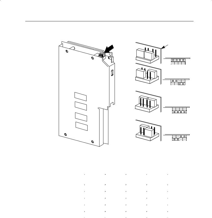
You do this by placing the LAST STATE configuration jumpers on eight (four jumpers on sets of pins) of the stake pins marked MAX, MIN, MID on the module's circuit board (Figure 2.1). If you do not place configuration jumpers in one of these positions, the module defaults to the HOLD LAST VALUE setting.
Figure 2.1 shows jumper positions for the 1771-OFE, Series B,
Analog Output Module LAST STATE Configuration Jumpers.
Important: Ignore the MAX, MIN, MID markings on the printed circuit board.
Important: On power-up, the module's output is disabled until the module receives the first block transfer write. The output then enables with the value that you send it in the block transfer write block.
Important: We ship 1771-OFE modules with the LAST STATE configuration jumpers in the MID position.
|
ATTENTION: Switch 1 of the I/O rack affects the |
||||||
! |
function of the configuration settings as indicated in |
||||||
the table below. |
|
|
|
|
|
||
|
|
|
|
|
|
||
|
|
|
|
|
|
|
|
|
|
|
|
|
|
|
|
|
|
|
Configuration Jumper Setting |
|
|
||
Rack Switch 1 |
|
|
|
|
|
|
|
|
Setting |
MIN |
MID |
MAX |
HOLD LAST STATE |
|
|
|
|
|
|||||
|
|
|
|
|
|
|
|
Last State |
Last State |
Last State |
Last State |
Last State |
|||
|
|
|
|
|
|
|
|
|
Reset |
Min |
Mid |
Max |
Last State |
||
|
|
|
|
|
|
|
|
Publication 77 " November 8
2-5
Figure 2.1
LAST STATE Configuration Jumper
Last State Output Level |
|
Configuration Jumpers |
Front of Circuit Board |
|
|
|
HOLD LAST STATE |
MIN
MID
MAX
Table 2.A lists the output ranges and their minimum, maximum, and middle values.
Table 2.A
Output Last State Configuration Values
Output Range |
Minimum |
Middle Value |
Maximum |
|
Selection |
Value |
Value |
||
|
||||
|
|
|
|
|
4020mA |
4mA |
12mA |
20mA |
|
|
|
|
|
|
0050mA |
0mA |
25mA |
50mA |
|
|
|
|
|
|
105V |
1V |
3V |
5V |
|
|
|
|
|
|
0010V |
0V |
5V |
10V |
|
|
|
|
|
|
+10V |
010V |
0V |
+10V |
|
|
|
|
|
These output conditions are active only if the following conditions exist:
•the module faults
•the processor is in the PROGRAM or TEST mode
•rack switch 1 is in the reset position
Publication 177106.5.30 - November 1998
2-6
Rack switch 1 determines what output conditions occur during a rack fault.
Rack Switch 1 |
|
Configuration Jumper Setting |
|
||
|
|
|
|
|
|
Setting |
MIN |
MID |
MAX |
HOLD LAST STATE |
|
|
|
||||
|
|
|
|
|
|
Last State |
Last State |
Last State |
Last State |
Last State |
|
|
|
|
|
|
|
Reset |
Min |
Mid |
Max |
Last State |
|
|
|
|
|
|
|
To set the last state configuration jumpers, proceed as follows.
ATTENTION: Do not insert modules into or remove modules from the I/O chassis while system power is
! ON. Failure to observe this rule could result in damage to module circuitry and unexpected machine operation.
1. Locate the jumpers as shown in Figure 2.1.
2. Carefully pull up on the jumpers to remove from the pins.
3. Reposition as necessary to provide the value selected in Table 2.A.
Setting Voltage Range Configuration Jumpers (1771-OFE1 only)
If you ordered the voltage output version, you must set several configuration jumpers located inside the module on the circuit board. To do this, follow these steps:
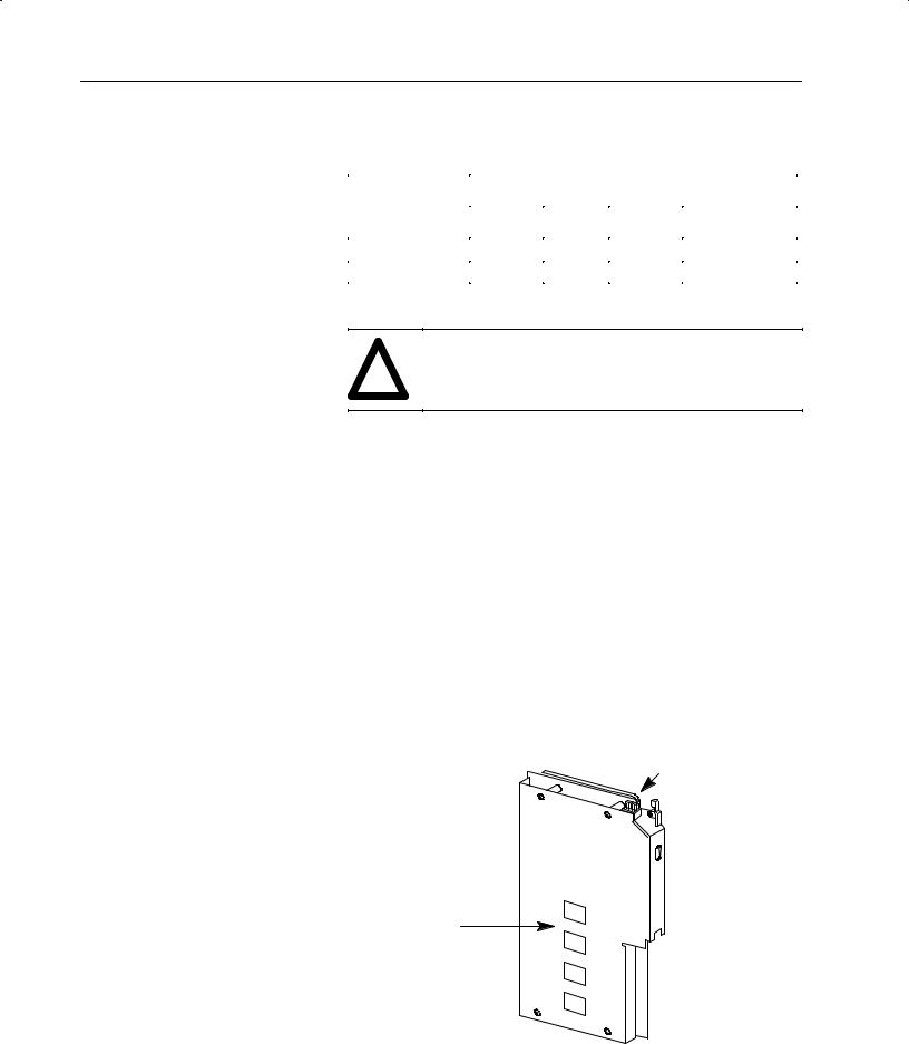
2.Locate the configuration jumpers and set them according to your output voltage requirements (Figure 2.3).
Last State Output Level
Configuration Jumpers
Access holes for
Configuration
Jumpers
5. Position the jumpers as indicated in Figure 2.3.
Publication 77 * November 8

2-7
Figure 2.3
Configuration Jumper Locations
|
Configuration |
Desired Voltage Range |
Output |
|||
|
|
|
||||
|
Jumper |
|
|
|
||
|
|
+ |
|
Channel |
||
LAST STATE |
|
|
0-10V |
1-5V |
||
Location |
- 10V |
|
||||
|
P3, Jumper |
5 |
In |
Out |
Out |
|
|
|
6 |
In |
Out |
Out |
|
|
|
7 |
Out |
In |
Out |
1 |
|
|
8 |
Out |
In |
Out |
|
|
|
|
||||
|
|
9 |
Out |
Out |
In |
|
|
|
10 |
Out |
Out |
In |
|
|
P5, Jumper |
5 |
In |
Out |
Out |
|
|
|
6 |
In |
Out |
Out |
|
|
|
7 |
Out |
In |
Out |
2 |
|
|
8 |
Out |
In |
Out |
|
|
|
|
||||
|
|
9 |
Out |
Out |
In |
|
|
|
10 |
Out |
Out |
In |
|
|
P7, Jumper |
5 |
In |
Out |
Out |
|
|
|
6 |
In |
Out |
Out |
|
|
|
7 |
Out |
In |
Out |
3 |
|
|
8 |
Out |
In |
Out |
|
|
|
|
||||
|
|
9 |
Out |
Out |
In |
|
In |
|
10 |
Out |
Out |
In |
|
Out |
P9, Jumper |
5 |
In |
Out |
Out |
|
|
6 |
In |
Out |
Out |
|
|
|
|
7 |
Out |
In |
Out |
4 |
(side view |
|
8 |
Out |
In |
Out |
|
|
|
|||||
of jumper) |
|
9 |
Out |
Out |
In |
|
|
|
10 |
Out |
Out |
In |
|
Install the Keying Bands
|
ATTENTION: Observe the following |
! |
precautions when inserting or |
removing keys: |
|
|
• Insert or remove keys with your |
|
fingers. |
|
• Make sure the key placement is |
|
correct |
|
Incorrect keying or the use of a tool can |
|
result in damage to the backplane |
|
connector and possible system faults. |
|
|
Position the keying bands in the backplane connectors to
correspond to the key slots on the module.
Place the keying bands: between 10 and 12 between 26 and 28
Upper
Connector
I/O chassis
You can change the position of these bands if subsequent system design and rewiring makes insertion of a different type of module necessary.
Publication 177186.5.30 - November 1998
2-8
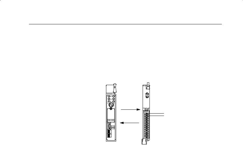
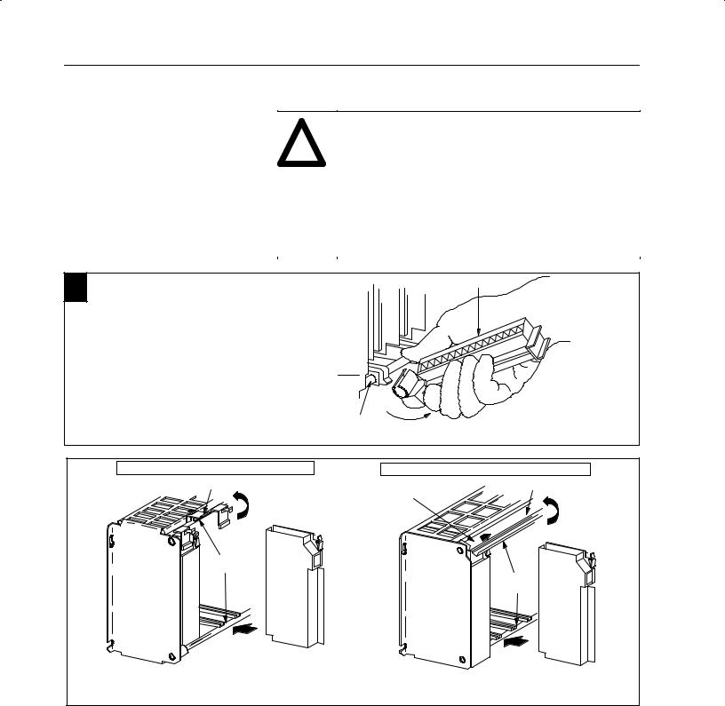
Install the Module and Field
Wiring Arm
|
ATTENTION: Remove power from the 1771 I/O |
! |
chassis backplane and field wiring arm before |
removing or installing an I/O module. |
|
|
• Failure to remove power from the backplane or |
|
wiring arm could cause module damage, degradation |
|
of performance, or injury. |
|
• Failure to remove power from the backplane could |
|
cause injury or equipment damage due to possible |
|
unexpected operation. |
|
|
1 |
|
wiring arm |
Attach the wiring arm (17715WC) to the horizontal |
|
|
|
bar at the bottom of the I/O chassis. |
|
|
The wiring arm pivots upward and connects with |
|
|
the module so you can install or remove the |
|
|
module without disconnecting the wires. |
17715WH |
|
|
remove
horizontal bar  install
17643
2 |
17715A1B, 5A2B, 5A3B, 5A3B1, 5A4B I/O chassis |
|
locking tab |
|
|
card guides
module
Snap the chassis latch over
the top of the module to secure it.
17715A1B, 5A2B, 5A3B1, 5A4B Series B I/O chassis
locking bar
locking bar pin
card guides
module Swing the chassis locking bar down into place to secure
the modules. Make sure the locking pins engage.
19809
Publication 177156.5.30 - November 1998
2-9
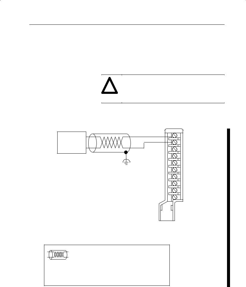
Connect the Wiring
The analog devices connect to the analog module through a field wiring arm (cat. no. 1771-WC). The field wiring arm pivots on the front of the I/O chassis to connect with the module. You can remove the module from the chassis without disconnecting user wiring because wiring connections are made on the field wiring arm. The connection diagram (Figure 2.5) shows connections to the field wiring arm.
ATTENTION: To avoid injury to personnel and damage to equipment, disconnect and lockout ac power
! from the processor and system power supplies before wiring the module.
Figure 2.5
Connection of Analog Devices to the Field Wiring Arm (cat. no. 1771$WC)
|
A |
User |
|
Analog |
0 |
|
|
Device |
|
|
1 |
|
2 |
Functional |
|
Ground |
3 |
|
4 |
5
6
7
B
Field Wiring Arm
Cat. No 1771:WC
The sensor cable must be shielded. The shield must:
•extend the length of the cable, but be connected only at the 1771 I/O chassis
•extend up to the point of termination
Important: The shield should extend to the termination point, exposing just enough cable to adequately terminate the inner conductors. Use heat shrink or another suitable insulation where the wire exits the cable jacket.
Channel 1 output (+) lead Channel 1 output (:) lead Channel 2 output (+) lead Channel 2 output (:) lead Channel 3 output (+) lead Channel 3 output (:) lead Channel 4 output (+) lead Channel 4 output (:) lead Not used
Not used
12878
Publication 1771:6.5.30 - November 1998

2-10
Ground the Chassis and
Module
The module requires shielded cable for signal transmission to the analog devices. Use Belden 8761 shielded cable, which consists of a single insulated, twisted-pair of conductors, covered along their entire length by a foil shield and encased in plastic. The shield reduces the effect of induced noise at any point along the cable.
You must ground the shield at the chassis end only. We recommend connecting each output cable's shield to a properly grounded common bus. Refer to ªIndustrial Automation Wiring and Grounding Guidelines for Noise Immunity,º publication 1770-4.1, for additional information.
Figure 2.6
Cable Grounding
Remove a length of cable jacket from the Belden 8761 cable.
Belden 8761 Cable
Pull the foil shield and bare drain wire from the insulated wires.
Bare drain wire
Insulated wires
Foil shield
Twist the foil shield and drain |
Attach a ground lug. |
wire together to form a single |
|
strand. |
|
20104
Chassis Ground
When you connect grounding conductors to the I/O chassis grounding stud, place a star washer under the first lug, then place a nut with captive lock washer on top of each ground lug.
Ground Lug
Nut
Nut and Captive
Washer
Grounding Stud
|
|
Star |
Ground Lug1 |
|
|
|
Washer |
||
I/O Chassis |
Shield and Drain |
|||
|
||||
Side Plate |
|
|||
|
twisted together |
|||
|
|
|
||
1Use the cup washer if crimp;on lugs are not used.
19480
Single point Grounding
Extend shield to termination point.
Expose just enough cable to adequately terminate inner conductors.
Use heat shrink tubing or other suitable insulation where wire exits cable jacket.
Shield and Drain twisted together
#10 Thread;forming screw
External;tooth
Washers
19923
Publication 1771;6.5.30 - November 1998

2-11
Interpreting the Indicator
Lights
Chapter Summary
The front panel of the module contains a green RUN and a red FLT (fault) indicator. At power-up, the red FLT indicator lights and remains ON during an initial module self-check. If a fault is found initially or occurs later, the red FLT indicator stays lit. If a fault is not found, the red indicator will turn off and the green RUN indicator will turn on and remain on.
Possible module fault causes and corrective actions are discussed in Chapter 7, ªDiagnostics and Troubleshooting.º
Figure 2.7
Diagnostic Indicators
ANALOG
OUT
(12 BIT)
RUN
FLT
17948
In this chapter, you learned how to set the module configuration jumpers, connect the field wiring to the field wiring arm, and install your module in the I/O chassis.
Publication 1771)6.5.30 - November 1998

2-12
P 77 8
 Loading...