


Installation Instructions
i r h i
(Cat. No. 1771-A1B, -A2B, -A3B, -A3B1, -A4B Series B)
he e
ch |
|
ee e |
|
|
|
"%$&( #( )' & #$&" ($# |
|
|
%& % & $& #'( !! ($# |
4 |
|
!!$+ ') #( "$)#( # '% |
|
4 |
"$)#( ( '' ' # &$)# )' |
8 |
|
&$)# ( '' ' |
|
|
' ( ( %$+ & ')%%!, $# )& ($# )"% & |
|
|
' ( ( '+ ( ' $# ( %! # '' " !, |
|
|
%&$* %$+ & ($ ( '' ' |
|
4 |
#'( !! "$)! ' |
|
|
-&$)' !$($# %%&$* ! |
8 |
|
'% ($#' |
|
|
|
|
|
e
Because of the variety of uses for the products described in this publication, those responsible for the application and use of these products must satisfy themselves that all necessary steps have been taken to assure that each application and use meets all performance and safety requirements, including any applicable laws, regulations, codes and standards. In no event will Allen±Bradley be responsible or liable for indirect or consequential damage resulting from the use or application of these products.
Any illustrations, charts, sample programs, and layout examples shown in this publication are intended solely for purposes of example. Since there are many variables and requirements associated with any particular installation, Allen±Bradley does not assume responsibility or liability (to include intellectual property liability) for actual use based upon the examples shown in this publication.
Allen±Bradley publication SGI±1.1, Safety Guidelines for Application, Installation, and Maintenance of Solid±State Control (available from your local Allen±Bradley office), describes some important differences between solid±state equipment and electromechanical devices that should be taken into consideration when applying products such as those described in this publication.
) ! ($# . 5 &

2 |
Universal I/O Chassis |
Reproduction of the contents of this copyrighted publication, in whole or part, without written permission of Rockwell Automation, is prohibited.
Throughout this publication, notes may be used to make you aware of safety considerations. The following annotations and their accompanying statements help you to identify a potential hazard. avoid a potential hazard, and recognize the consequences of a potential hazard.
WARNING
!
Identifies information about practices or circumstances that can cause an explosion in a hazardous environment, which may lead to personal injury or death, property damage, or economic loss.
Identifies information about practices or ATTENTION circumstances that may lead to personal injury
or death, property damage, or economic loss.
!
Identifies information that is critical for IMPORTANT successful application and understanding of the
product.
Publication 1771 IN075A EN P March 2002
Universal I/O Chassis |
3 |
Environment and Enclosure
ATTENTION
This equipment is intended for use in a Pollution
Degree 2 industrial environment, in overvoltage
!Category II applications (as defined in IEC publication 60664±1), at altitudes up to 2000
meters without derating.
This equipment is considered Group 1, Class A industrial equipment according to IEC/CISPR Publication 11. Without appropriate precautions, there may be potential difficulties ensuring electromagnetic compatibility in other environments due to conducted as well as radiated disturbance.
This equipment is supplied as ªopen typeº equipment. It must be mounted within an enclosure that is suitably designed for those specific environmental conditions that will be present, and appropriately designed to prevent personal injury resulting from accessibility to live parts. The interior of the enclosure must be accessible only by the use of a tool. Subsequent sections of this publication may contain additional information regarding specific enclosure type ratings that are required to comply with certain product safety certifications.
See NEMA Standards publication 250 and IEC publication 60529, as applicable, for explanations of the degrees of protection provided by different types of enclosures. Also, see the appropriate sections in this publication, as well as the Allen±Bradley publication 1770±4.1, (ªIndustrial Automation Wiring and Grounding Guidelinesº), for additional installation requirements pertaining to this equipment.
Publication 1771 IN075A EN P March 2002
4 Universal I/O Chassis
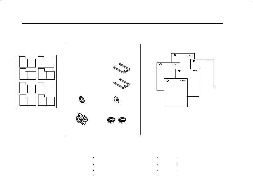
Prepare for Installation |
Make sure you have these items: |
||
I O group label set (cat. no. 1771;XB) |
Hardware kit (cat. no. 1771;RK) |
Documentation |
|
|
|
|
(if you are installing I/O modules or power supplies) |
plastic keying bands
(number depends on size of chassis)
• 9 |
1771;A1B |
• 18 |
1771;A2B |
• 27 |
1771;A3B, 1771;A3B1 |
• 36 |
1771;A4B |
1 star washer |
1 cup washer |
4 flat washers |
2 #10-32 nuts |
|
with captive lock washers |
I/O Module |
|
Cat. No. 1771; |
|
User Manual |
|
|
Power Supply Chassis |
|
Cat. No. 1771; |
Power Supply |
Installation Data |
Cat. No. 1771;P |
|
Installation Data |
|
Power Supply Modules |
|
Cat. No. 1771; |
|
Installation Data |
|
Output Module |
|
Cat. No. 1771; |
|
Installation Data |
|
for your:
•programmable controller or I/O adapter module
•external power supply and/or power supply chassis (if you are using external power supplies)
•communication modules and/or I/O modules
•power;supply modules
Allow Sufficient
Mounting Space
For these mounting dimensions |
See page |
|
|
I/O chassis |
6 |
|
|
I/O chassis with external power supply |
7 |
|
|
Make sure you meet these minimum spacing requirements.
Publication 1771;IN075A-EN-P - March 2002

Universal I/O Chassis |
5 |
B
153mm
(6")
A
102mm  (4")
(4")
C
102mm |
D |
153mm |
|
(6") |
|||
(4") |
|||
|
|||
|
|
E51mm (2")
w r n u t
E
51mm (2")
102mm
(4")
C
|
153mm (6") |
w r n u t |
DD |
|
|
|
|
A
M n mum st n tw n m or ompon nt n t s s o n n losurs 102mm (4 n s).
BM n mum v rt l s p r t on tw n m or ompon nts s 153mm (6 n s).
CM n mum or zont l s p r t on tw n m or ompon nts s 102mm (4 n s).
D
M n mum v rt l st n tw n m or ompon nt n t top orottom o n n losur s 153mm (6 n s).
E |
M n mum st n tw n m or ompon nts n w r n u ts or t rm n l |
|
str ps s 51mm (2 n s). |
|
|
|
13082 |
u l t on 1771,IN075A-EN- - M r 2002
6 |
Universal I/O Chassis |
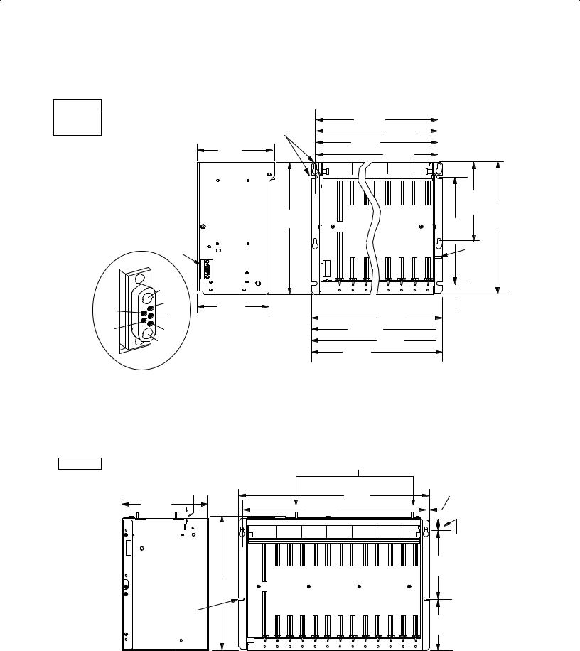
I O Cha i Mo n ing Dimen ion
17713A1B |
use four 1/4320 (M6 x 10) |
|
|
|
17713A2B |
|
|
||
mounting bolts to secure, using |
593mm |
|
||
17713A3B1 |
|
|||
slots, keyholes, or a |
|
|||
(23.32") |
466mm |
|||
17713A4B |
||||
combination of both |
|
|||
|
(18.32") |
|||
|
|
339mm |
||
|
193mm1 |
|
||
|
(13.32") |
212mm |
||
|
(7.60") |
|||
|
|
|||
|
|
(8.32") |
||
|
|
|
315mm
(12.41")
power connector
A1
1 |
3 |
171mm |
|
|
|
|
|||
4 |
(6.75") |
610mm |
||
|
||||
|
|
(24.01") |
||
2 |
5 |
483mm |
||
(19.01") |
356mm |
|||
|
|
|||
|
A2 |
229mm |
(14.01") |
|
|
|
|
||
|
|
(9.01") |
|
A1 backplane common
A2 backplane +5V dc
1no connection
2 backplane processor enable
3backplane +5V dc sense
4 backplane signal ground sense
5no connection
1771 A3B |
|
grounding studs |
18mm |
|
|
(0.71") |
|
483mm |
217mm1 |
465mm |
(19.01") |
(8.54") |
(18.31") |
|
339mm
(13.35")
use 1/4320 (M6 x 10) mounting bolts (four places)
16-slot
12-slot
8-slot
4-slot
178mm
(7.00")
307mm 254mm (12.09")
(10")
grounding stud
 25.4mm (1.0")
16-slot 1771-A4B
 12-slot 1771-A3B1
  8-slot 1771-A2B
4-slot 1771-A1B
13445
9mm
(0.34")
26mm
(1.02")
178mm
(7")
130mm
(5.10")
1Total maximum depth dimension per installation depends on module |
124503I |
wiring and connectors. |
|
Publication 17713IN075A-EN-P - March 2002
 Loading...