


 Loading...
Data Highway or Data Highway Plus Asynchronous (RS-232-C or RS-422-A) Interface Module
Cat. No. 1770-KF2)
User Manual

Important User Information |
Because of the variety of uses for the products described in this publication, |
||
|
those responsible for the application and use of this control equipment must |
||
|
satisfy themselves that all necessary steps have been taken to assure that each |
||
|
application and use meets all performance and safety requirements, including |
||
|
any applicable laws, regulations, codes and standards. |
||
|
The illustrations, charts, sample programs and layout examples shown in this |
||
|
guide are intended solely for purposes of example. Since there are many |
||
|
variables and requirements associated with any particular installation, the |
||
|
Allen-Bradley Company, Inc. does not assume responsibility or liability (to |
||
|
include intellectual property liability) for actual use based upon the examples |
||
|
shown in this publication. |
||
|
Allen-Bradley Publication SGI-1.1, ªSafety Guidelines for the Application, |
||
|
Installation and Maintenance of Solid State Controlº (available from your local |
||
|
Allen-Bradley office) describes some important differences between solid-state |
||
|
equipment and electromechanical devices which should be taken into |
||
|
consideration when applying products such as those described in this |
||
|
publication. |
||
|
Reproduction of the contents of this copyrighted manual, in whole or in part, |
||
|
without written permission of the Allen-Bradley Company Inc. is prohibited. |
||
|
Throughout this manual we use notes to make you aware of safety |
||
|
considerations: |
||
|
|
|
|
|
ATTENTION: Identifies information about practices or |
||
|
circumstances that can lead to personal injury or death, property |
||
|
damage or economic loss. |
||
|
|
|
|
|
Attentions help you: |
||
|
identify a hazard |
||
|
avoid the hazard |
||
|
recognize the consequences |
||
|
Important: Identifies information that is especially important for |
||
|
successful application and understanding of the product. |
||
|
Interchange, ControlView, Data Highway Plus and DH+ are trademarks and PLC is a registered |
||
|
trademark of Allen-Bradley Company, Inc. |
||
|
HART is a registered trademark of Rosemount Inc. |
||
|
IBM is a registered trademark of International Business Machines Corporation. |
||

Table of Contents
Introduction . . . . . . . . . . . . . . . . . . . . . . . . . . . . . . . . . . . . |
1 1 |
|
General . . . . . . . . . . . . . . . . . . . . . . . . . . . . . . . . . . . . . . . . . . . |
|
1 1 |
About This Manual . . . . . . . . . . . . . . . . . . . . . . . . . . . . . . . . . . . |
|
1 1 |
Module Description . . . . . . . . . . . . . . . . . . . . . . . . . . . . . . . . . . |
|
1 3 |
Specifications . . . . . . . . . . . . . . . . . . . . . . . . . . . . . . . . . . . . . . |
|
1 4 |
Data Highway Applications . . . . . . . . . . . . . . . . . . . . . . . . . . . . . |
|
1 5 |
. . . . . . . . . . . . . . . . . . . . . . . . . . . . . . . . . . . .PCL Applications |
|
1 7 |
Communication Concepts . . . . . . . . . . . . . . . . . . . . . . . . . |
2 1 |
|
General . . . . . . . . . . . . . . . . . . . . . . . . . . . . . . . . . . . . . . . . . . . |
|
2 1 |
Physical Link Layer . . . . . . . . . . . . . . . . . . . . . . . . . . . . . . . . . . |
|
2 2 |
Software Layers . . . . . . . . . . . . . . . . . . . . . . . . . . . . . . . . . . . . . |
|
2 8 |
Installation . . . . . . . . . . . . . . . . . . . . . . . . . . . . . . . . . . . . . |
|
3 1 |
|
General . . . . . . . . . . . . . . . . . . . . . . . . . . . . . . . . . . . . . . . . . . . |
|
3 1 |
|
. . . . . . . . . . . . . . . . . . . . . . . . .Communication Option Switches |
|
3 1 |
|
Mounting (Placing) . . . . . . . . . . . . . . . . . . . . . . . . . . . . . . . . . . . |
|
3 8 |
|
Interface Connections . . . . . . . . . . . . . . . . . . . . . . . . . . . . . . . . . |
|
3 9 |
|
Diagnostic Indicators . . . . . . . . . . . . . . . . . . . . . . . . . . . . . . . . . |
3 18 |
||
Asynchronous Link Protocols . . . . . . . . . . . . . . . . . . . . . . |
|
4 1 |
|
General . . . . . . . . . . . . . . . . . . . . . . . . . . . . . . . . . . . . . . . . . . . |
|
4 1 |
|
Definition of Link Protocol . . . . . . . . . . . . . . . . . . . . . . . . . . . . . . |
|
4 1 |
|
Full Duplex Protocol . . . . . . . . . . . . . . . . . . . . . . . . . . . . . . . . . . |
|
4 2 |
|
Half Duplex Protocol . . . . . . . . . . . . . . . . . . . . . . . . . . . . . . . . . |
4 21 |
||
Message Packet Formats . . . . . . . . . . . . . . . . . . . . . . . . . . |
5 1 |
|
General . . . . . . . . . . . . . . . . . . . . . . . . . . . . . . . . . . . . . . . . . . . |
|
5 1 |
Application Layer . . . . . . . . . . . . . . . . . . . . . . . . . . . . . . . . . . . . |
|
5 1 |
Network Layer . . . . . . . . . . . . . . . . . . . . . . . . . . . . . . . . . . . . . . |
|
5 1 |
Message Packets . . . . . . . . . . . . . . . . . . . . . . . . . . . . . . . . . . . |
|
5 3 |
Message Formats . . . . . . . . . . . . . . . . . . . . . . . . . . . . . . . . . . . |
|
5 7 |
Data Encoding and Addressing . . . . . . . . . . . . . . . . . . . . . |
6 1 |
|
General . . . . . . . . . . . . . . . . . . . . . . . . . . . . . . . . . . . . . . . . . . . |
|
6 1 |
Data Encoding . . . . . . . . . . . . . . . . . . . . . . . . . . . . . . . . . . . . . . |
|
6 1 |
Addressing . . . . . . . . . . . . . . . . . . . . . . . . . . . . . . . . . . . . . . . . |
|
6 8 |
ii |
Table of Contents |
Error Reporting . . . . . . . . . . . . . . . . . . . . . . . . . . . . . . . . . |
|
7 1 |
|
General . . . . . . . . . . . . . . . . . . . . . . . . . . . . . . . . . . . . . . . . . . . |
7 1 |
||
ERROR WORD in User Programming |
|
|
|
(1771 KG, 1771 KA, 1771 KA2, 1774 KA Modules) . . . . . . . . . |
|
7 2 |
|
Error Codes for 1775 KA . . . . . . . . . . . . . . . . . . . . . . . . . . . . . . |
|
7 8 |
|
Internal Error Counters . . . . . . . . . . . . . . . . . . . . . . . . . . . . . . . . |
7 19 |
||
Switch Settings . . . . . . . . . . . . . . . . . . . . . . . . . . . . . . . . . |
|
A 1 |
General . . . . . . . . . . . . . . . . . . . . . . . . . . . . . . . . . . . . . . . . . . . |
|
A 1 |
Message Formats . . . . . . . . . . . . . . . . . . . . . . . . . . . . . . . |
|
B 1 |
General Asynchronous Link Error Codes (STS, EXT STS) . |
|
C 1 |
Where to Find Asynchronous Link Error Codes . . . . . . . . . . . . . . . |
|
C 1 |
The STS Byte . . . . . . . . . . . . . . . . . . . . . . . . . . . . . . . . . . . . . . |
|
C 1 |
The EXT STS Byte . . . . . . . . . . . . . . . . . . . . . . . . . . . . . . . . . . . |
|
C 3 |
Detailed Flowcharts . . . . . . . . . . . . . . . . . . . . . . . . . . . . . . |
|
D 1 |
General . . . . . . . . . . . . . . . . . . . . . . . . . . . . . . . . . . . . . . . . . . . |
|
D 1 |
Data Link Layer . . . . . . . . . . . . . . . . . . . . . . . . . . . . . . . . . |
|
E 1 |
Data Link Layer Operation on Data Highway . . . . . . . . . . . . . . . . . |
|
E 1 |
Floating Master . . . . . . . . . . . . . . . . . . . . . . . . . . . . . . . . . . . . . |
|
E 1 |
Message Transmission . . . . . . . . . . . . . . . . . . . . . . . . . . . . . . . . |
|
E 3 |
Polling . . . . . . . . . . . . . . . . . . . . . . . . . . . . . . . . . . . . . . . . . . . . |
|
E 3 |
Data Security . . . . . . . . . . . . . . . . . . . . . . . . . . . . . . . . . . . . . . . |
|
E 4 |
Link Disconnect . . . . . . . . . . . . . . . . . . . . . . . . . . . . . . . . . . . . . |
|
E 5 |

Chapter 1
Introduction
General |
A 1770-KF2 Series B module is a communication interface that links |
|
intelligent RS-232-C or RS-422-A (asynchronous) devices to an |
|
Allen-Bradley local area network. By setting switches on the KF2, and |
|
changing cables, you can direct communications over a Data Highway or |
|
a Peer Communication Link (PCL). With a 1770-KF2 module, a |
|
computer on a PCL can communicate with any PLC-5 node on the |
|
network. Other current Allen-Bradley products that communicate over a |
|
PCL are the 1784-T50 Industrial Terminal System and the 1785-KA |
|
Communication Adapter Module. |
|
The KF2 is designed to operate in a control-room environment on a |
|
tabletop. It takes its power from an AC wall outlet, and it gives you a |
|
choice of full-duplex or half-duplex protocol on its asynchronous link. |
|
The module has Data Highway compatibility, and it supports all PCL |
|
facilities except internetworking. |
|
(Internetworking would indicate that a computer on a PCL could talk to a |
|
node on another PCL, or to a station on a Data Highway link. That may |
|
be possible in the future, but it isn't right now. A computer on a Data |
|
Highway, though, using a 1770-KF2 and a 1785-KA can communicate |
|
with PLC-5s on a PCL.) |
About This Manual |
This manual describes installation, operation, and communication |
|
protocols of a 1770-KF2 module; and it assumes that you are already |
|
thoroughly familiar with how to program your computer or other |
|
intelligent asynchronous device. It does not assume prior knowledge of |
|
the Allen-Bradley Data Highway or a Peer Communication Link. |
|
Table 1.A lists related documentation that might be helpful in conjunction |
|
with this manual. For more details about the programming and operation |
|
of specific Allen-Bradley programmable controllers, refer to the |
|
appropriate user's manual for that controller. |
1-1

Chapter 1
Introduction
Table 1.A
Related Documentation
Publication |
Old Publication |
Title |
Number |
Number |
|
|
|
|
1770-6.2.1 |
1770-810 |
Data Highway Cable Assembly and Installation |
|
|
Manual |
|
|
|
1771-6.5.1 |
1771-801 |
Communication Adapter Module |
|
|
(Cat. No. 1771-KA2) User's Manual |
|
|
|
1771-6.5.15 |
1771-822 |
Communication Controller Module |
|
|
(Cat. Nos. 1771-KE, -KF) User's Manual |
|
|
|
1771-6.5.8 |
1771-811 |
PLC-2 Family/RS-232-C Interface Module |
|
|
(Cat. No. 1771-KG) User's Manual |
|
|
|
1775-6.5.1 |
1775-802 |
PLC-3 Communication Adapter Module |
|
|
(Cat. No. 1775-KA) User's Manual |
|
|
|
1773-6.5.2 |
1773-801 |
PLC-4 Communication Interface Module |
|
|
(Cat. No. 1773-KA) User's Guide |
|
|
|
1785-6.8.1 |
|
PLC-5/15 Processor Manual |
|
|
|
1785-6.6.1 |
|
PLC-5/15 Assembly & Installation Manual |
|
|
|
6226-6.5.1 |
|
Industrial Terminal Support Software System |
|
|
Manual |
|
|
|
1784-6.5.1 |
|
Industrial Terminal (1784-T50) User's Manual |
|
|
|
1785-6.5.1 |
|
PCL-to-Data Highway Communication Adapter |
|
|
Module (1785-KA) User's Manual |
|
|
|
This manual is organized as follows:
Chapter 2 Ð Explains basic communication concepts. Chapter 3 Ð Tells how to install a KF2 module.
Chapters 4, 5, and 6 Ð Describe the communication protocol used by a KF2 module.
Chapter 7 Ð Summarizes error reporting.
1-2
Chapter 1
Introduction
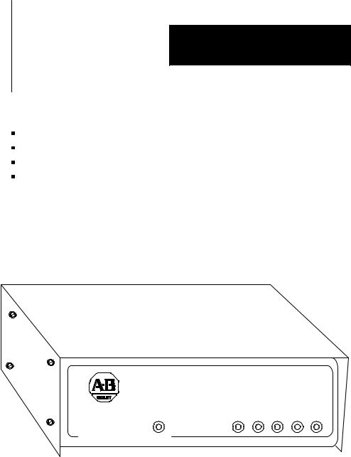
Module Description |
Figure 1.1 shows the 1770-KF2 module's hardware features: |
Diagnostic Indicators
Connectors for Data Highway and RS-232-C Devices
Communication Option Switches
On/Off Switch, Power Plug, Fuse, and Voltage Select Switch
Figure 1.1
1770-KF2 Communication Interface Module
ALLEN±BRADLEY
PWR |
XMTG RCVG RDY ACTV CPU |
DATA HIGHWAY
COMMUNICATION INTERFACE
A KF2 also features extensive self-diagnostics. At power-up, tests are run on internal memory, timers, and firmware integrity. Any failure causes the red front-panel CPU indicator to flash. Also, the module continuously checks the memory and firmware during operation.
1-3

Chapter 1
Introduction
Specifications |
Table 1.B lists KF2 module specifications. |
||
|
Table 1.B |
|
|
|
KF2 Module Specifications |
|
|
|
|
|
|
|
Specification |
|
Requirements |
|
|
|
|
|
Communication Rates |
• |
Data Highway: 57,600 bits per second (recommended) |
|
|
• Peer Communication Link: 57,600 bits per second |
|
|
|
|
(recommended) |
|
|
• Asynchronous: Switch selectable from 110 to 9.600 bits |
|
|
|
|
per second |
|
|
|
|
|
Functions |
• |
Interface a programmable RS-232-C or RS-422-A |
|
|
|
compatible device with an Allen-Bradley Data Highway. |
|
|
• Serve as a replacement for a 1771-KD Communication |
|
|
|
|
Controller Module. |
|
|
|
|
|
Location |
• |
Tabletop (or other horizontal surface) |
|
|
• Controlled environment, e.g., office or control room |
|
|
|
|
|
|
Communication Ports |
• |
Data Highway: 15-pin male EIA D-connector |
|
|
• Peer Communication Link: 15-pin male EIA |
|
|
|
|
D-connector |
|
|
• Data Highway Monitor: 9-pin female EIA D-connector |
|
|
|
• |
Asynchronous (RS-232-C/RS-422-A): 25-pin male |
|
|
|
EIA D-connector |
|
|
|
|
|
Cabling |
• |
Data Highway: Data Highway Dropline Cable |
|
|
|
(Cat. No. 1770-CD) |
|
|
• Asynchronous RS-232-C: User-Supplied Data |
|
|
|
|
Terminal Interface Cable or Modem Interface Cable |
|
|
• Asynchronous RS-422-A: User-Supplied Data Terminal |
|
|
|
|
Interface Cable |
|
|
|
|
|
Power Requirements |
• |
Selectable: 115 V/60 Hz or 230 V/50 Hz |
|
|
• |
Watts: 3.5 |
|
|
|
|
|
Ambient Temperature |
• |
32oF to 113oF (0oC to 45oC) Operational |
|
Rating |
• |
-40oF to 185oF (-40oC to 85oC) Storage |
|
Ambient Humidity Rating |
• |
10% to 80% Non-Condensing |
|
Physical |
• |
Size: 10-3/8 in. x 10.0 in. x 3-3/8 in. (263.5 mm x |
|
|
|
254 mm x 85.7 mm) |
|
|
• Weight: 6.0 pounds (2.7 Kg) |
|
|
|
|
|
1-4

Chapter 1
Introduction
Data Highway Applications |
A KF2 module provides either a point-to-point link or a multi-drop link |
||||||
|
between an Allen-Bradley Data Highway and an intelligent asynchronous |
||||||
|
device. By ªintelligent asynchronous deviceº we mean any device that |
||||||
|
complies with RS-232-C or RS-422-A electrical standards and that can be |
||||||
|
programmed to handle the communication protocol described in |
||||||
|
Chapters 4 through 6 of this manual. Throughout this manual, we will |
||||||
|
also use the term ªcomputerº in a general sense to refer to this type of |
||||||
|
device. Some examples include: |
|
|
||||
|
|
An Allen-Bradley Advisor 2+TM Color Graphic System |
|
|
|||
|
|
A PLC-3 Programmable Controller and Connected Communication |
|||||
|
|
Adapter Module (Cat. No. 1775-KA) |
|
|
|||
|
|
A PLC-2 Family Programmable Controller and Connected PLC-2 |
|||||
|
|
Family/RS-232-C Interface Module (Cat. No. 1771-KG) |
|
|
|||
|
|
A PLC-4 Microtrol Programmable Controller and Connected |
|||||
|
|
Communication Interface Module (Cat. No. 1773-KA) |
|
|
|||
|
|
A Variety of Minicomputers and Microcomputers |
|
|
|||
|
In point-to-point configuration, the KF2 module connects one intelligent |
||||||
|
asynchronous device as a single station on a Data Highway. Figure 1.2 |
||||||
|
illustrates this configuration. Point-to-point links can use either peer-to- |
||||||
|
peer (full-duplex) or master-slave (half-duplex) communication. |
||||||
|
Figure 1.2 |
|
|
||||
|
Point-to-Point Links |
|
|
||||
|
|
|
|
|
|
|
|
|
|
Computer |
|
|
|
|
|
|
|
|
|
|
|
|
|
|
|
|
|
|
|
|
|
|
|
Modem |
|
|
|
|
|
|
|
|
|
Modem Link |
|
|
|
|
|
|
|
|
Computer |
|
|
|
|
Modem |
Asynchronous Link |
|
|
||
|
|
|
|
|
|||
|
|
|
|
|
|
|
|
|
|
|
|
(50 Cable-Ft. Max.) |
|
|
|
|
|
KF2 Module |
|
KF2 Module |
|
||
|
|
|
|
|
|||
|
|
|
|
|
|
|
|
KF2 Module
Allen±Bradley Longline
RS-232-C Link  Data Highway Link
(7,000 Cable-Ft. Max.)
1771-KG
Module
PLC-2/30
Processor
11687
1-5

Chapter 1
Introduction
In a multi-drop configuration, one intelligent asynchronous device connects to several Data Highways through sets of modems and KF2 modules. Figure 1.3 illustrates this type of configuration. If the multi-drop link consists of broadband modems, you can select either peer-to-peer (full-duplex) or master-slave (half-duplex) communication. If the multi-drop link consists of baseband modems, you must use master-slave (half-duplex) communication because baseband modems support only one communication channel.
|
|
|
|
|
|
|
|
|
|
Figure 1.3 |
|
|
|
|
|
|||
|
|
|
|
|
|
|
|
|
|
Multi-Drop Link |
|
|
|
|
|
|||
|
|
|
|
|
|
|
|
|
|
|
|
|
|
|
|
|
||
|
|
|
|
|
|
|
|
|
|
|
Computer |
|
|
|
|
|
|
|
|
|
|
|
|
|
|
|
|
|
|
|
|
|
|
|
|
|
|
|
|
|
|
|
|
|
|
|
|
|
|
|
|
|
|
|
|
|
|
|
|
|
|
|
|
|
|
|
|
Modem |
|
|
|
|
|
|
|
|
|
|
|
|
|
|
|
|
|
|
|
|
|
|
Multi-Drop Modem Link |
|||
|
|
|
|
|
|
|
|
|
|
|
|
|
|
|
||||
|
|
|
|
|
|
|
|
|
|
|
|
|
|
|
|
|
|
|
|
|
|
|
|
|
|
|
|
|
|
|
|
|
|
|
|
|
|
|
|
Modem |
|
|
|
|
|
|
|
|
|
|
|
Modem |
||||
|
|
|
|
|
|
|
|
|
|
|
|
|
|
|
|
|
|
|
|
|
|
|
|
|
|
|
|
|
|
|
|
|
|
|
|
|
|
|
|
KF2 Module |
|
|
|
|
|
|
|
|
|
|
|
1771-KG |
||||
|
|
|
|
|
|
|
|
|
|
|
|
|
Module |
|||||
|
|
|
|
|
|
|
|
|
|
|
|
|
|
|
|
|
||
|
|
|
|
|
|
|
|
|
Data Highway Link |
|
|
|
|
|
||||
|
|
|
|
|
|
|
|
|
|
|
|
PLC-2/15 |
||||||
|
|
|
|
|
|
|
|
|
|
|
|
|
|
|
|
|
||
|
|
|
|
|
|
|
|
|
|
|
|
|
|
|
|
|
Processor |
|
|
|
|
|
|
|
|
|
|
|
|
|
|
|
|
|
|||
|
|
|
|
|
|
|
|
|
|
|
|
|
|
|
|
|||
|
|
|
|
|
|
|
|
|
|
|
|
|
|
|
|
|
|
|
1775-KA |
|
|
|
1773-KA |
|
|
|
|
|
Modem |
|
|
|
|
||||
Module |
|
|
|
Module |
|
|
|
|
|
|
|
|
|
|
||||
|
|
|
|
|
|
|
|
|
|
|
|
|
||||||
|
|
|
|
|
|
|
|
|
|
|
|
|
|
|
|
|
|
|
PLC-3 |
|
|
|
PLC-4 |
|
|
|
|
|
|
|
|
|
|
||||
|
|
|
Microtrol |
|
|
|
|
|
|
|
|
|
|
|||||
Processor |
|
|
|
|
|
|
|
|
|
|
|
|
|
|||||
|
|
|
Processor |
|
|
|
|
|
KF2 Module |
|
|
|
|
|||||
|
|
|
|
|
|
|
|
|
|
|
|
|
|
|
||||
|
|
|
|
|
|
|
|
|
|
|
|
|
|
|
|
Data Highway Link |
||
|
|
|
|
|
|
|
|
|
|
|
|
|
|
|
|
|
|
|
|
|
|
|
|
|
|
|
|
|
|
KF2 Module |
|
|
1771-KA |
|
1774-KA |
||
|
|
|
|
|
|
|
|
|
|
|
|
|
Module |
|
Module |
|||
|
|
|
|
|
|
|
|
|
|
|
|
|
|
|
|
|||
|
|
|
|
|
|
|
|
|
|
|
|
|
|
|
|
|
|
|
|
|
|
|
|
|
|
|
|
|
|
|
|
|
|
PLC-2 |
|
PLC |
|
|
|
|
|
|
|
|
|
|
|
|
Computer |
|
|
Processor |
|
Processor |
||
|
|
|
|
|
|
|
|
|
|
|
|
|
|
|
|
|
||
|
|
|
|
|
|
|
|
|
|
|
|
|
|
|
|
11688 |
||
|
|
|
|
|
|
|
|
|
|
|
|
|
|
|
|
|||
1-6
Chapter 1
Introduction
In either type of configuration, there are three possible ways you can connect a KF2 module:
Direct connection to an intelligent asynchronous device if the KF2 module is mounted within 50 cable-feet of an RS-232-C, or within 4,000 cable-feet of an RS-422-A device.
Direct connection to an Allen-Bradley 1775-KA, 1773-KA, or 1771-KG interface module if the KF2 module is within 50 cable-feet of the other module.
Modem connection if the KF2 module is within 50 cable-feet of an RS-232-C compatible modem, or within 4,000 cable-feet of an RS-422-A device.
|
You can also use the 1770-KF2 module to replace a 1771-KD module in |
|
an existing application. By properly setting the option switches on the |
|
KF2 module, you can make this replacement without having to change |
|
any application programs that you were using with the 1771-KD module. |
|
Refer to Chapter 3 under ªReplacing a 1771-KD Module with a KF2 |
|
Moduleº for switch settings. |
PCL Applications |
A 1770-KF2 Series B module provides either a point-to-point or |
|
multi-drop link between an Allen-Bradley Peer Communication Link |
|
(PCL) and an intelligent asynchronous device. You can use a PCL link |
|
when you have a small number of PLC-5/15 stations in a local cluster. |
|
Typically, a PCL link connects PLC-5/15s that need to communicate with |
|
each other frequently. If your system requires more than ten stations, |
|
consider breaking it into smaller PCL links connected by a Data Highway |
|
to optimize performance. |
|
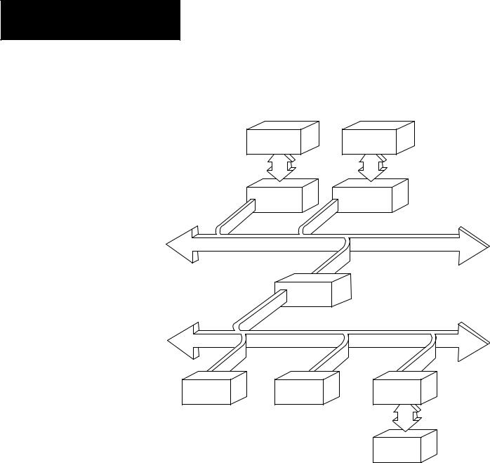
The KF2 Series B module provides an interface between either: |
|
an RS-232-C or RS-422-A asynchronous link to Data Highway, or |
|
an RS-232-C or RS-422-A asynchronous link to a PCL network as |
|
shown in Figure 1.4. |
1-7
Chapter 1
Introduction
Figure 1.4
A PCL Network Connected to a Data Highway
Advisor 2+TM |
PLC-3 |
1770-KF2 |
1775-KA |
Data Highway
1785-KA
PCL
PLC-5 |
PLC-5 |
1770-KF2 |
Computer
14690
Important: A 1770-KF2 module on a PCL link cannot access a station on the Data Highway through a 1785-KA module. A KF2 module on the Data Highway, however, can access a station on a PCL link through a 1785-KA.
1-8

Chapter 2
Communication Concepts
General |
This chapter presents some of the concepts of communication with the |
|
KF2 module. It describes the physical communication links to the module |
|
and the various levels of software necessary to make those links work. |
|
A KF2 module connects a computer or programmable controller to an |
|
Allen-Bradley local area network (LAN), either Data Highway or Peer |
|
Communication Link (PCL). In doing so, the module acts as an interface |
|
between two physical communication links: |
|
Data Highway or PCL, Called ªNetwork Linkº |
|
RS-232-C or RS-422-A, Called ªAsynchronous Linkº |
|
A Data Highway network provides peer-to-peer communication between |
|
the KF2 module and other stations on the Data Highway. It uses a |
|
half-duplex (polled) protocol and rotation of link mastership. |
|
A Peer Communication Link provides peer-to-peer communication |
|
between the KF2 module and other stations on the PCL. The PCL uses |
|
token-passing to control access to the link. |
|
The asynchronous link can provide either peer-to-peer communication |
|
through a full-duplex (unpolled) protocol, or master-slave communication |
|
through a half-duplex (polled) protocol. |
|
In addition to a physical link layer, communication on either the network |
|
link or the asynchronous link involves three levels of software: |
|
Application Layer |
|
Network Layer |
|
Data Link Layer |
|
If you are using a computer on an asynchronous link, you must program |
|
all three layers. For A-B programmable controllers, you need program |
|
only the application layer; the Data Highway interface modules (or for the |
|
PCL, the PLC-5 itself) automatically take care of the other two layers. |
|
The rest of this chapter presents some of the concepts behind the physical |
|
communication links and their three software layers. For more details on |
2-1

Chapter 2
Communication Concepts
|
the application and network layers, refer to Chapters 5 and 6. For more |
|
on the data link layer of the asynchronous link, refer to Chapter 4 and |
|
Appendix D. |
Physical Link Layer |
The physical link layer is a set of cables and interface modules that work |
|
together to provide a channel for communication between the various |
|
points, called stations, on the physical link. A station consists of an |
|
intelligent programmable device (e.g., PC or computer) and the module or |
|
modules that interface it with the physical link. |
|
In this way, the KF2 module allows stations on one link to communicate |
|
with stations on the other link. Since these two physical links have |
|
different communication protocols, the KF2 module serves mainly as a |
|
protocol translator. |
|
Data Highway |
|
The Data Highway and the PCL are both local area networks (LANS) that |
|
allow peer-to-peer communication among up to 64 stations. Figure 2.1 |
|
illustrates a Data Highway network. |
|
The Data Highway link consists of a trunkline that can be up to |
|
10,000 feet long and droplines that can be up to 100 feet each. Each |
|
station is at the end of a dropline. |
|
A Data Highway link implements peer-to-peer communication through a |
|
modified token-passing scheme called the floating master. With this |
|
arrangement, each station has equal access to become the master. The |
|
stations bid for temporary mastership based on their need to send |
|
information. |
|
Unlike a master/slave relationship, a floating master relationship does not |
|
require the current master to poll each station to grant permission to |
|
transmit. Therefore, it provides a more efficient network because there is |
|
less overhead per transaction. |
2-2

Chapter 2
Communication Concepts
Figure 2.1
Data Highway Network
PLC-3 |
|
|
|
|
|
|
|
|
|
|
Computer |
|
|
|
|
|
|
||
Processor |
|
|
|
|
|
|
|
||
|
|
|
|
|
|
|
|
|
|
1775-KA |
|
|
|
|
|
Advisor 2+TM |
|
||
Module |
|
|
|
|
|
|
|
|
|
MODEM |
|
|
|
|
|
|
|||
|
|
|
|
|
|
|
|
||
|
|
MODEM |
|
|
RS-232-C Link |
||||
|
|
|
|
|
|
||||
|
|
|
|
|
|
||||
|
|
|
|
|
|
50 Cable-Ft. Max. |
|||
|
|
|
|
Link |
|
|
|||
|
|
|
|
|
|
|
|
||
|
|
|
|
|
|
|
|
|
|
|
|
MODEM |
|
|
|
|
|
|
|
|
|
|
|
1770-KF2 |
|
||||
|
|
|
|
|
|
|
|||
|
|
|
|
|
|
Module |
|
||
|
|
|
|
|
|
||||
|
|
|
|
|
|
|
|
|
|
|
|
|
|
|
|
|
|
|
|
|
|
1770-KF2 |
|
|
|
|
|
|
|
|
|
Module |
|
|
|
|
|
Data |
|
|
|
|
|
|
|
|
|
|
|
|
|
|
|
|
|
|
|
|
Highway |
|
|
|
|
|
|
||||
|
|
|
|
|
|
|
|
|
Link |
|
|
|
|
|
|
|
|
|
|
|
|
|
|
1770-KF2 |
|
|
|
|
|
|
|
Module |
|
|
|
|
|
|
|
|
|
|
|
|
|
|
RS-232-C Link |
|
|
|
|
|
|
|
50 Cable-Ft. Max. |
|
|
|
|
|
|
|
|
|
|
1771-KA |
|
1773-KA |
|
1771-KG |
|||
Module |
|
Module |
|
Module |
|||
|
|
|
|
|
|
|
|
PLC-2/15 |
|
PLC-4 |
|
PLC-2/30 |
|||
Processor |
|
Loop |
|
Processor |
|||
|
|
|
|
|
|
|
|
11299A
Stations
A station consists of a computer or PC processor and the module or modules that interface it with the Data Highway link. Within a station that contains a KF2 module, an asynchronous link is required as an auxiliary link to the network. Figure 2.1 shows three such stations.
2-3

Chapter 2
Communication Concepts
One station consists of an Advisor 2+TM Color Graphic System connected to a KF2 module through an RS-232-C link limited to 50 cable-feet. Another station consists of a computer interfacing with a KF2 module through a modem link that is limited only by the nature of the modems themselves.
The third such station consists of a 1771-KG module interfacing a PLC-2/30 processor with a KF2 module through an RS-232-C link limited to 50 cable-feet. If you want a link longer than 50 cable-feet, you can use modems.
PC Programming
All Allen-Bradley PC processors can be connected to a Data Highway through an appropriate station interface module. All of these processors can receive and reply to command messages, and some of them can also transmit command messages. For an explanation of how to program PCs to send and receive messages, refer to the user's manual for the appropriate station interface module.
Computer Programming
The communication protocol for the Data Highway link is transparent to a computer on the network. However, for a computer to send or receive messages through the Data Highway network, it must be programmed to communicate with its KF2 module over an asynchronous link.
Chapters 4, 5, and 6 describe the protocol that you must program your computer to use on such an asynchronous link.
Peer Communication Link
A PCL has much the same topology as the Data Highway, described in the previous chapter; but it is designed for fewer, closely coupled, PCs. The PCL implements peer-to-peer communication with a token-passing scheme to rotate link mastership among the stations connected to that link. Since such a method does not require any polling, it is very time efficient. The PCL also uses timeouts to recover from any fault that disables the station that has the token.
2-4

Chapter 2
Communication Concepts
Stations
A station consists of a computer, or PC processor, and the module or modules that interface it with the PCL. Within a station that contains a KF2 module, an asynchronous link is required as an auxiliary link to the network. PCL networks currently use PLC-5 processors, which interface directly to the PCL; and no station interface module is required. You can, however, connect other PCs, as shown in Figure 2.2.
Figure 2.2
PCL Network Connected to Various PC Processors
PLC-4 |
|
PLC-3 |
|
PLC-2/30 |
|||
Loop |
|
Processor |
|
Processor |
|||
|
|
|
|
|
|
|
|
1773-KA |
|
1775-KA |
|
1771-KG |
|||
Module |
|
Module |
|
Module |
|||
|
|
|
|
|
|
|
|
|
|
|
|
|
|
|
|
KF2 |
|
KF2 |
|
KF2 |
Module |
|
Module |
|
Module |
|
|
|
|
|
PCL
11300A
Other PCL stations can be computers that interface with the KF2 module either directly or through a modem link, or a PCL-to-Data Highway communication adapter (1785-KA), which you can use to connect a PCL to the Data Highway.
PC Programming
All Allen-Bradley PC processors can receive command messages and reply to them, and some can transmit commands. For an explanation of how to program PCs to send and receive messages, refer to the user's manual for that particular station interface module or, in the case of a PLC-5, the processor itself.
2-5

Chapter 2
Communication Concepts
Computer Programming
The communication protocol for the PCL is transparent to a computer on the network. However, for a computer to send or receive messages through the PCL, it must be programmed to communicate with its KF2 module over an asynchronous link. Chapters 4, 5, and 6 describe the protocol that you must program your computer to use on this link.
Configuration Selection
Figure 2.1 and Figure 2.2 illustrate configurations in which PC stations can communicate with each other and with computers through network ports and asynchronous ports on the station interface modules. Each configuration is useful, depending on your application.
If you want to provide a peer-to-peer communication among many PCs and/or a computer, use a Data Highway network as shown in Figure 2.1. For communication among a small cluster of PCs and a computer, use a PCL as shown in Figure 1.4. For distances longer than the networks provide, you can use an auxiliary longline asynchronous (RS-232-C or RS-422-A) link or a modem link.
A Data Highway link has a communication rate of 57,600 bits per second and a half-duplex (peer-to-peer, polled) protocol. A KF2 asynchronous link is selectable RS-232-C/RS-422-A and has a selectable communication rate up to 9,600 bits per second. It uses a selectable protocol of half-duplex (master-slave polled) or full-duplex (peer-to-peer, unpolled).
A master-slave communication protocol can be selected for any link to a computer. A peer-to-peer communication protocol can be selected only for a point-to-point link or a broadband modem multi-drop link to a computer.
Even with only two stations, you may want a Data Highway or a Peer Communication Link. Either network provides the flexibility of easy reconfiguration or expansion if you want to be able to add more stations later, and it also provides more error checking than an asynchronous link.
2-6

Chapter 2
Communication Concepts
Configuration Considerations
Allen-Bradley manufactures a variety of communication interface modules for different applications:
|
|
Communication Interface Module |
Cat. No. |
Note |
|
|
|
|
|
|
PLC Communication Adapter Module |
1774-KA |
1 |
|
|
PLC-2 |
Family Communication Adapter Module |
1771-KA2 |
1 |
|
||||
|
PLC-3 |
Communication Adapter Module |
1775-KA |
|
|
1 & 2 |
|||
|
PLC-4 |
Communication Interface Module |
1773-KA |
|
|
1 & 2 |
|||
|
PLC-5/Data Highway Communication Adapter Module |
1785-KA |
|
|
|
±± |
|||
|
PLC-2 |
Family/RS-232-C Interface Module |
1771-KG |
|
|
2 |
|||
|
Communication Controller Modules |
1771-KE, -KF |
|
|
|
3 |
|||
|
Communication Interface Module |
1770-KF2B |
|
|
|
3 |
|||
|
|
|
|
|
|
Provides interface between: |
|
|
|
1A PC Processor and a Data Highway Communication Link
2A PC Processor and an RS-232-C Communication Link
3A RS-232-C Communication Link and a Data Highway Communication Link
A 1785-KA module interfaces a Data Highway with a Peer Communication Link. The module resides in a 1771 I/O rack and receives its power from the rack's backplane.
A 1771-KE module must be installed in an I/O chassis. The 1771-KD, 1771-KF, and 1770-KF2 are standalone modules. Modules 1771-KE, 1771-KF, and 1770-KF2 provide either peer-to-peer or master-slave communication between an RS-232-C link, or to a modem link, and the Data Highway.
RS-422-A/Data Highway Interface
A 1770-KF2 provides an interface between an RS-422-A communication link and a Data Highway communication link. The 1770-KF2 is functionally identical to the 1771-KF except that it is a desktop module, provides its own power supply, and supports both RS-232-C and RS-422-A communication.
RS-232-C/RS-422-A Ð PCL Interface
A 1770-KF2 provides an interface between an RS-232-C or RS-422-A asynchronous link and a Peer Communication Link network.
2-7

Chapter 2
Communication Concepts
Software Layers |
Each of the physical links just described requires three layers of software |
|
to enable communication to take place. The layers are defined as follows: |
|
Application Layer Ð Controls and executes the actual tasks, or |
|
commands, specified in the communication between stations. To |
|
program this layer, use the commands described in Chapter 5. |
|
Network Management Layer Ð Handles queueing, sequencing, |
|
routing, and error status reporting for communication. If your physical |
|
link contains only Allen-Bradley PCs, you do not have to program this |
|
layer. Otherwise, refer to Chapter 5 for a description of how to |
|
program this layer for an asynchronous link to a computer. |
|
Data Link Layer Ð Controls the flow of communication over the |
|
physical link by establishing, maintaining, and releasing the |
|
communication channel between stations. If your physical link |
|
contains only Allen-Bradley PCs, you do not have to program this |
|
layer. Otherwise, refer to Chapter 4 for a description of how to |
|
program this layer for an asynchronous link to a computer. |
|
Application Layer |
|
The application layer concerns the specific commands that you can |
|
program at a given station to cause that station to communicate over the |
|
link. This layer is the same for both asynchronous and network links. |
|
The types of commands that a station can transmit and receive vary with |
|
the type of processor at that station. Chapter 5 describes the commands |
|
that each type of PC processor can transmit or receive. To program your |
|
computer to communicate with a PC, use the appropriate command |
|
message format shown in Chapter 5. |
|
Message Structures |
|
All messages on a network have the same fundamental structure, |
|
regardless of their function or destination. If you could freeze a block |
|
while it is in transmission, you would see two types of message bytes: |
|
Protocol Bytes |
|
Data Bytes |
|
Protocol bytes are used by the network to get the message to its |
|
destination. Data bytes are delivered to the application at the destination. |
|
The methods by which these bytes are filled is determined by the nature |
|
of the station from which the transmission block originates. For example, |
|
if a transaction originates from a PC station, the station interface module |
2-8
Chapter 2
Communication Concepts
automatically fills the protocol bytes. If the transaction originates from a computer station, your computer software must supply the necessary protocol. In both cases, the data bytes contain information supplied by application programs.
Command/Reply Cycle
Any network transaction consists of two messages: a command and a reply.
The two parts provide extra data integrity by ensuring that a required action always returns some sort of status, whether an error code or data. As a frame of reference, the command initiator is always referred to as a local station, and a reply initiator is always referred to as a remote station. Unless noted otherwise, whether in a network link or an asynchronous link, our reference will be limited to a single local station and a single remote station.
The network layer protocol distinguishes a command from a reply. Obviously, the data area of a command and its corresponding reply depend on the type of command.
Priority
Each message on a Data Highway link is classified as either high priority or normal priority.
Each message on a PCL is classified as normal priority.
Priority levels of messages determine the order in which stations are polled and allowed to transmit messages. In the polling process, stations with high priority messages will always be given priority over stations with normal priority messages.
You specify the priority level for each command in the message command code. The station that receives a command message must establish the same priority level for its corresponding reply message.
Important: Stations with high priority messages are given priority over stations with normal priority messages throughout the command/reply message cycle. For this reason, a command should be given a high priority designation only when special handling of specific data is
2-9

Chapter 2
Communication Concepts
required. Using an excessive number of high priority commands defeats the purpose of this feature and could delay or inhibit the transmission of normal priority messages.
Command Structures
There are four basis types of command on a Data Highway network or a standalone link:
Read
Write
Diagnostic
Mode Select
Reads
There are two types of read:
Physical
Unprotected
A physical read allows you to read any area of PC memory at a remote station. However, a PC processor cannot originate a physical read command; only a computer can originate a physical read.
An unprotected read can access only the data table area of PC memory.
Both computers and PCs can initiate unprotected reads.
Any read can request up to 122 16-bit words of contiguous data from PC memory.
Writes
We can classify write commands both by their application and by their level of memory access.
As an application issue, writes are divided between bit writes and word writes. Bit writes allow the local station to control bits in the data table of a remote station.
Word writes allow the local station to write up to 121 contiguous words of data into the remote station's memory, provided you abide by the restrictions on memory access discussed next.
2-10

Chapter 2
Communication Concepts
As with reads, writes also are classified by the level of access to PC memory. Non-physical writes can access only the data table at a remote PC; physical writes can access all of user memory, including PC program memory.
Non-physical writes can be further subdivided into protected and unprotected. Protected writes can access only specified areas of the remote PC's data table memory. The accessible areas are defined by memory protection rungs in the remote PC's ladder diagram program. Unprotected writes, on the other hand, can access any area of the remote PC's data table.
In most cases, switch settings on the remote station's interface module can disable the module from executing each of these types of write commands.
Diagnostics
Diagnostic commands have to originate from a device other than a PC. You can use these commands to return status information from a remote or local station or to alter some on-board parameters at a station interface module. Diagnostic commands are particularly useful during a start-up or during on-line debugging.
Mode Select
Mode select commands allow you to load a new PC program from a remote computer station. The operation of these commands varies by PC processor type. These commands can be issued only by a computer.
Network Management Layer
The network management layer is concerned with the specifics of conveying a message safely from its source to its destination. This layer is the same for both asynchronous and network links.
If your physical link contains only Allen-Bradley PCs, you do not have to program anything for this layer; the communication interface modules automatically take care of it. If your physical link contains a computer, then refer to Chapter 5 for a description of how to program this layer at the computer station.
2-11

Chapter 2
Communication Concepts
Generally, you need not be concerned with the interaction of station interface modules on the network.
This means that your application programs at the PCs and computers along the network need not involve themselves with interstation protocol, handshaking, or control of the network link. This is all carried out automatically by the station interface modules. However, an understanding of station interaction is useful both to computer programmers and PC programmers. It allows optimum use of network commands and fault diagnostics.
Error Checking
Error codes can be generated at two places: remote station modules and local station interface modules. For codes that are returned from a local station module, two types of condition can exist:
Application programs use the wrong message format or issue illegal commands.
The local station cannot complete a transaction due to network problems.
A remote station can return only the codes associated with an application problem at the remote station. Typically, these involve either the PC processor being off-line (in Program mode, for example) or the command trying to access memory areas blocked by either the interface module or the user application program.
In the network layer protocol, command message status is returned in a reply status byte. A value of zero in the status byte indicates successful transmission of the corresponding command. It is up to the local application program to display and act on the value of the returned byte.
2-12

Chapter 3
Installation
General |
This chapter explains how to install the 1770-KF2 module. There are four |
|
parts to installation: |
|
Setting Communication Option Switches |
|
Situating the Module for Operation |
|
Connecting the Module to the Network and Asynchronous Links |
|
Observing the Diagnostic Indicators |
|
Please read the first three chapters of this manual carefully before |
|
attempting any of the installation steps. |
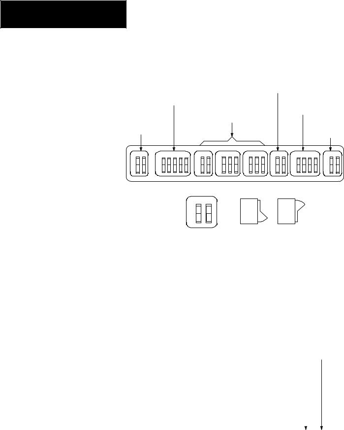
Communication Option Switches The KF2 module has 8 switch assemblies (Figure 3.1) that enable you to select various communication options. The switch assemblies and their corresponding options are:
Switch Assembly |
Communication Option |
SW-1 |
Asynchronous Link Features |
SW-2, SW-3, SW-4 |
Station Number |
SW-5 |
Network Link Communication Rate |
SW-6 |
Asynchronous Link Communication Rate and Diagnostic |
|
Commands |
SW-7 |
Selecting the Network Link |
SW-8 |
RS-232-C/RS-422-A Selection |
3-1
Chapter 3
Installation
Figure 3.1
Communication Option Switches
|
|
|
|
Network Link |
|
|
|
|
|
|
|
|
Communication |
|
|
||
|
Asynchronous Link |
|
Rate (SW-5) |
|
|
|
||
|
|
|
|
Asynchronous Link |
||||
|
Features (SW-1) |
|
|
|
||||
|
|
|
|
|
|
Communication |
||
|
|
|
Station Number |
|
Rate (SW-6) |
|
||
|
|
|
|
|
|
|
||
RS-232-C/RS-422-A |
|
(SW-2, SW-3, SW-4) |
|
|
Network Link |
|||
|
|
|
|
|
||||
|
|
|
|
|
Selection |
|||
Selection (SW-8) |
|
|
|
|
|
|
||
|
|
|
|
|
|
(SW-7) |
||
|
|
|
|
|
|
|
||
O 1 2 |
O 1 2 3 4 5 |
O 1 2 O 1 2 3 |
O 1 2 3 |
O 1 2 |
O |
1 2 3 4 |
O 1 2 |
|
N |
N |
N |
N |
N |
N |
N |
|
N |
O |
O |
O |
O |
O |
O |
O |
|
O |
F |
F |
F |
F |
F |
F |
F |
|
F |
F |
F |
F |
F |
F |
F |
F |
|
F |
|
|
Front View |
Side |
|
|
|
|
|
|
|
O 1 |
2 |
ON ON ON |
|
|
||
|
|
N |
|
|
|
|||
|
|
O |
|
OFF |
OFF |
OFF |
|
|
|
|
F |
|
13529 |
||||
|
|
F |
|
|
|
|
|
|
|
|
|
|
|
|
|
|
|
Important: The KF2 reads the status of the communication option switches only at power-up, so you must make your selection with the KF2's power off.
Asynchronous Link Features
The following table shows you how to set the asynchronous link features using Switch Numbers 1, 2, and 5.
If You Want |
|
|
With |
|
|
|
|
|
|
|
to Select |
With Error |
With |
Embedded |
|
|
SW-1 |
|
|
||
Protocol as: |
Check as: |
Parity as: |
Responses: |
|
|
|
|
|
|
|
1 |
2 |
3 |
|
4 |
5 |
|||||
|
|
|
|
|
|
|
|
|
|
|
Full Duplex |
BCC |
None |
No |
OFF |
OFF |
N/A |
N/A |
OFF |
||
Full Duplex |
BCC |
Even |
No |
ON |
OFF |
|
|
|
OFF |
|
|
|
|
||||||||
|
|
|
|
|
|
|
|
|
|
|
Full Duplex |
BCC |
None |
Yes |
OFF |
ON |
|
|
|
OFF |
|
|
|
|
|
|
|
|
|
|
|
|
Full Duplex |
BCC |
Even |
Yes |
ON |
ON |
|
|
|
OFF |
|
|
|
|
|
|
|
|
|
|
|
|
Half Duplex |
BCC |
None |
No |
OFF |
OFF |
|
|
|
ON |
|
|
|
|
|
|
|
|
|
|
|
|
Half Duplex |
BCC |
Even |
No |
ON |
OFF |
|
|
|
ON |
|
|
|
|
|
|
|
|
|
|
|
|
Full Duplex |
CRC |
None |
Yes |
OFF |
ON |
|
|
|
ON |
|
|
|
|
|
|
|
|
|
|
|
|
Half Duplex |
CRC |
None |
No |
ON |
ON |
|
|
|
ON |
|
|
|
|
||||||||
|
|
|
|
|
|
|
|
|
|
|
3-2

Chapter 3
Installation
Switch 3 determines whether the asynchronous port of the KF2 module can detect duplicate messages transmitted to it.
If You Want Your Module to: |
Set Switch 3: |
|
|
|
|
Detect and Ignore Duplicate Messages |
ON |
|
Accept All Messages Regardless of Duplication |
OFF |
|
|
|
Switch 4 determines whether the module uses and recognizes the following handshaking signals: data set ready, request to send, clear to send, data carrier detect, and data terminal ready.
If You Want the Module's Asynchronous Port to: |
Set Switch 4: |
|
|
|
|
Use Handshaking Signals |
ON |
|
Ignore Handshaking Signals |
OFF |
|
|
|
Important: If you select half-duplex, the KF2 uses handshaking signals even if Switch 4 is set OFF.
Station Number
Switch Assemblies SW-2, SW-3, and SW-4 are for setting the network station number of the KF2 module. For the Data Highway, the station number is a 3-digit octal number that identifies the KF2 module as a unique station. Valid station numbers for the KF2 module in Data Highway mode are 010 to 077 and 110 to 376 octal. For a PCL, the station number is 2 digits; set both switches in SW-2 OFF. Valid station numbers for the KF2 in PCL mode are 00 to 77 octal.
Figure 3.2 shows an example of how to set the KF2 station number to 037 octal. The switches in Assembly SW-2 set the first (left-most) digit of the station number; Switch Assembly SW-3 sets the middle digit; and Switch Assembly SW-4 sets the last (right-most) digit.
Station numbers play an important part in the polling scheme described in Chapter 2. They can also influence the order in which mastership is transferred between network stations. Therefore, we recommend that you always begin numbering stations with the lowest possible number and continue with the next available number in sequence.
3-3

Chapter 3
Installation
Figure 3.2
Station Number
Switch Groups
SW-2 |
SW-3 |
SW-4 |
ON |
ON |
O 1 2 |
O 1 2 3 |
O 1 2 |
OFF |
|
3 |
|
|||
N |
N |
N |
|
|
O |
O |
O |
ON |
|
F |
F |
F |
|
|
|
|
|||
F |
F |
F |
OFF |
OFF |
First Digit
If You Want |
Set Switches |
|
|
|
|
to Set This |
|
|
|
|
|
Digit: |
No. 1 |
No. 2 |
|
|
|
0 |
OFF |
OFF |
1 |
OFF |
ON |
2 |
ON |
OFF |
3 |
ON |
ON |
|
|
|
Second and Third Digits
If You Want |
|
Set Switches |
||
|
|
|
|
|
to Set This |
|
|
|
|
|
|
|
|
|
Digit: |
No. 1 |
|
No. 2 |
No. 3 |
|
|
|
|
|
0 |
OFF |
|
OFF |
OFF |
1 |
OFF |
|
OFF |
ON |
2 |
OFF |
|
ON |
OFF |
3 |
OFF |
|
ON |
ON |
4 |
ON |
|
OFF |
OFF |
5 |
ON |
|
OFF |
ON |
6 |
ON |
|
ON |
OFF |
7 |
ON |
|
ON |
ON |
|
|
|
|
|
Switch Setting Example: Station No. 037
Switch Group |
SW-2 |
|
SW-3 |
|
|
SW-4 |
|
||
|
|
|
|
|
|
|
|
|
|
Station No. Digits |
|
0 |
|
3 |
|
|
7 |
|
|
|
|
|
|
|
|
|
|
|
|
Switch No. |
1 |
|
2 |
1 |
2 |
3 |
1 |
2 |
3 |
|
|
|
|
|
|
|
|
|
|
Switch Setting |
OFF |
|
OFF |
OFF |
ON |
ON |
ON |
ON |
ON |
|
|
|
|
|
|
|
|
|
|
13531
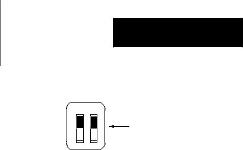
Network Communication Rate
Switch Assembly SW-5 lets you select the communication rate for the KF2 module's network link.
Important: Set both switches ON for a network communication rate of 57,600 bits per second. Be sure to set all modules on the network link for this communication rate.
3-4
Chapter 3
Installation
Figure 3.3
Switch Settings for Network Link
SW±5
O 1 2
N
Both switches ON for
O 57,600 bits per second
F
F
13514
Asynchronous Communication Rate and Diagnostic Commands
Switch Assembly SW-6 lets you select the communication rate and diagnostic commands for the KF2 module's asynchronous port.
Communication Rate
Set the communication rate switches as shown:
Bits per |
|
Set Switch: |
|
|||
Second as: |
|
|
|
|
|
|
1 |
|
2 |
|
|
3 |
|
|
|
|
|
|
|
|
110 |
OFF |
|
OFF |
|
OFF |
|
|
ON |
|
OFF |
|
|
OFF |
300 |
|
|
|
|||
|
|
|
|
|
|
|
600 |
OFF |
|
ON |
|
|
OFF |
|
|
|
|
|
|
|
1,200 |
ON |
|
ON |
|
|
OFF |
|
|
|
|
|
|
|
2,400 |
OFF |
|
OFF |
|
|
ON |
|
|
|
|
|
|
|
4,800 |
ON |
|
OFF |
|
|
ON |
|
|
|
|
|
|
|
9,600 |
OFF |
|
ON |
|
|
ON |
Diagnostic Commands
Switch 4 determines how the KF2 module treats diagnostic commands sent to it by a remote Data Highway station. You can connect the asynchronous port of the KF2 module directly to a 1771-KG, 1773-KA, or 1775-KA communication interface module (Figure 1.2). In such applications, you can set Switch 4 so that the KF2 module either executes any received diagnostic commands itself or passes those commands to the other attached communication module.
If You Want Your Module to: |
Set Switch 4: |
|
|
|
|
Execute Received Diagnostic Commands |
ON |
|
Pass Any Received Diagnostic Commands to the |
OFF |
|
Attached Asynchronous Device |
|
|
|
|
3-5
Chapter 3
Installation
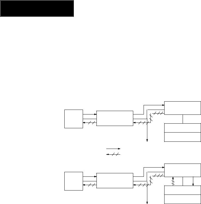
Switch 4 relates only to diagnostic commands sent to the KF2 module from a remote Data Highway station. Since only computers can transmit diagnostic commands, the remote station must be a computer connected to the Data Highway by means of another KF2 module. At the computer station, the setting of Switch 4 does not affect any diagnostic commands that the computer sends to its local KF2 module. The local module always retransmits the command message over the Data Highway without executing it. Figure 3.4 illustrates these concepts.
Figure 3.4
Effect of Switch 4 on Diagnostic Commands
|
|
Switch 4 ON |
|
|
1770-KF2 Module |
Computer |
1770-KF2 Module |
|
|
Data |
1771-KG Module |
|
Highway |
|
|
Link |
PLC-2/15 Processor |
|
To Other Stations |
|
Diagnostic Command Path |
|
|
Reply Message Path |
|
|
|
|
Switch 4 OFF |
|
|
1770-KF2 Module |
Computer |
1770-KF2 Module |
|
|
Data |
1771-KG Module |
|
Highway |
|
|
Link |
PLC-2/15 Processor |
|
|
|
|
To Other Stations |
|
11691
You can have more than one computer station on a network, and one computer can transmit diagnostic commands to the others. At the receiving computer station, if Switch 4 is OFF, the local KF2 module will pass the diagnostic commands to the computer. In such cases, you will have to write computer application programs to handle those commands at the receiving station. If Switch 4 is ON at the receiving station, the local KF2 module itself will execute the incoming diagnostic commands.
3-6
Loading...