


 Loading...
Installation Instructions
Compact I/O DeviceNet Scanner Module
(Cat. No. 1769-SDN)
Inside... |
|
For More Information.............................................................................. |
2 |
European Communities (EC) Directive Compliance ................................ |
3 |
Hazardous Location Considerations ....................................................... |
4 |
Environnements dangereux .................................................................... |
4 |
Module Description ................................................................................ |
5 |
Module Installation................................................................................. |
6 |
System Planning ..................................................................................... |
8 |
System Assembly.................................................................................... |
9 |
System Mounting.................................................................................. |
10 |
Replacing the Scanner Module within a System ................................. |
13 |
Field Wiring Connections...................................................................... |
14 |
Scanner Module Power-Up................................................................... |
15 |
Configuring the 1769-SDN on DeviceNet............................................. |
16 |
Data Organization ................................................................................. |
17 |
Diagnostic Indicators ............................................................................ |
18 |
Error Codes............................................................................................ |
19 |
Specifications ....................................................................................... |
21 |
Publication 1769-IN060C-EN-P - May 2002

2 Compact I/O DeviceNet Scanner Module
For More Information
For |
Refer to this Document |
Pub. No. |
|
|
|
A more detailed description of how to use |
Compact I/O DeviceNet Scanner |
1769-UM009A-EN-P |
your DeviceNet Scanner Module |
Module User Manual |
|
|
|
|
Detailed information on planning, |
CompactLogix System User Manual |
1769-UM007C-EN-P |
mounting, wiring, and troubleshooting your |
|
|
CompactLogix System. |
|
|
|
|
|
Detailed information on planning, |
MicroLogix 1500 Programmable |
1764-UM001A-US-P |
mounting, wiring, and troubleshooting your |
Controllers User Manual |
|
MicroLogix 1500 System. |
|
|
|
|
|
DeviceNet network planning information. |
DeviceNet Cable System Planning and |
DN-6.7.2 |
|
Installation Manual |
|
|
|
|
More information on proper wiring and |
Industrial Automation Wiring and |
1770-4.1 |
grounding techniques. |
Grounding Guidelines |
|
|
|
|
If you would like a manual, you can:
•download a free electronic version from the internet: www.theautomationbookstore.com
•purchase a printed manual by:
–contacting your local distributor or Rockwell Automation representative
–visiting www.theautomationbookstore.com and placing your order
–calling 1.800.963.9548 (USA/Canada)
or 001.330.725.1574 (Outside USA/Canada)
TIP
Translated versions of these Installation Instructions are available electronically. Obtain a translated version of this publication at www.theautomationbookstore.com.
Publication 1769-IN060C-EN-P - May 2002
Compact I/O DeviceNet Scanner Module |
3 |
|
|
European Communities (EC) Directive Compliance
This product carries the CE mark and is approved for installation within the European Union and EEA regions. It has been designed and tested to meet the following directives.
EMC Directive
This product is tested to meet the Council Directive 89/336/EC Electromagnetic Compatibility (EMC) by applying the following standards, in whole or in part, documented in a technical construction file:
•EN 50081-2 EMC — Generic Emission Standard, Part 2 — Industrial Environment
•EN 50082-2 EMC — Generic Immunity Standard, Part 2 — Industrial Environment
This product is intended for use in an industrial environment.
Low Voltage Directive
This product is tested to meet Council Directive 73/23/EEC Low Voltage, by applying the safety requirements of EN 61131-2 Programmable Controllers, Part 2 - Equipment Requirements and Tests. For specific information required by
EN 61131-2, see the appropriate sections in this publication, as well as the Allen-Bradley publication Industrial Automation Wiring and Grounding Guidelines For Noise Immunity, publication 1770-4.1. and the Automation Systems Catalog, B111.
This equipment is classified as open equipment and must be mounted in an enclosure during operation to provide safety protection.
Publication 1769-IN060C-EN-P - May 2002
4 Compact I/O DeviceNet Scanner Module
Hazardous Location Considerations
This equipment is suitable for use in Class I, Division 2, Groups A, B, C, D or non-hazardous locations only. The following WARNING statement applies to use in hazardous locations.
WARNING
!
EXPLOSION HAZARD
•Substitution of components may impair suitability for Class I, Division 2.
•Do not replace components or disconnect equipment unless power has been switched off or the area is known to be non-hazardous.
•Do not connect or disconnect components unless power has been switched off or the area is known to be non-hazardous.
•This product must be installed in an enclosure. All cables connected to the product must remain in the enclosure or be protected by conduit or other means.
•All wiring must comply with N.E.C. article 501-4(b).
Environnements dangereux
Cet équipement est conçu pour être utilisé dans des environnements de Classe 1, Division 2, Groupes A, B, C, D ou non dangereux. La mise en garde suivante s’applique à une utilisation dans des environnements dangereux.
DANGER D’EXPLOSION
AVERTISSEMENT
•La substitution de composants peut rendre cet équipement impropre à une utilisation en environnement de Classe 1,
!Division 2.
•Ne pas remplacer de composants ou déconnecter l'équipement sans s'être assuré que l'alimentation est coupée et que l'environnement est classé non dangereux.
•Ne pas connecter ou déconnecter des composants sans s'être assuré que l'alimentation est coupée ou que l'environnement est classé non dangereux.
•Ce produit doit être installé dans une armoire.
Publication 1769-IN060C-EN-P - May 2002

Compact I/O DeviceNet Scanner Module |
5 |
|
|
Module Description
|
2A |
1 |
3A |
|
8B |
8A |
4 |
|
8B |
|
5 |
|
9 |
7A
6
3B
2B
7B
Table A
1 |
bus lever (with locking function) |
6 |
grounding screw |
|
|
|
|
2A |
upper DIN rail latch |
7A |
DeviceNet mating male receptacle |
|
|
|
|
2B |
lower DIN rail latch |
7B |
removable DeviceNet female connector |
|
|
|
|
3A |
upper panel mounting tab |
8A |
movable bus connector with female pins |
|
|
|
|
3B |
lower panel mounting tab |
8B |
bus connector with male pins |
|
|
|
|
4 |
Module and Network status LEDs |
9 |
nameplate label |
|
|
|
|
5 |
Address and Error numeric displays |
|
|
|
|
|
|
Publication 1769-IN060C-EN-P - May 2002
6 Compact I/O DeviceNet Scanner Module
Module Installation
The 1769-SDN module is suitable for use in an industrial environment when installed in accordance with these instructions. Specifically, this equipment is intended for use in clean, dry environments (Pollution Degree 2(1)) and with circuits not exceeding Over Voltage Category II(2) (IEC 60664-1).(3)
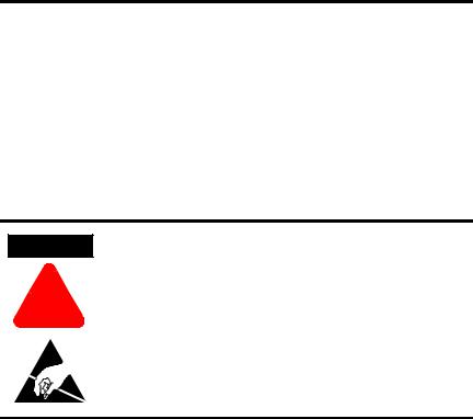
Prevent Electrostatic Discharge
Electrostatic discharge can damage integrated circuits or ATTENTION semiconductors if you touch bus connector pins. Follow these
guidelines when you handle the module:
!• Touch a grounded object to discharge static potential.
•Wear an approved wrist-strap grounding device.
•Do not touch the bus connector or connector pins.
•Do not touch circuit components inside the module.
•If available, use a static-safe work station.
• When not in use, keep the module in its static-shield box.
(1)Pollution Degree 2 is an environment where, normally, only non-conductive pollution occurs except that occasionally a temporary conductivity caused by condensation shall be expected.
(2)Over Voltage Category II is the load level section of the electrical distribution system. At this level transient voltages are controlled and do not exceed the impulse voltage capability of the product’s insulation.
(3)Pollution Degree 2 and Over Voltage Category II are International Electrotechnical Commission (IEC) designations.
Publication 1769-IN060C-EN-P - May 2002

Compact I/O DeviceNet Scanner Module |
7 |
|
|
Remove Power
Remove power before removing or inserting this module. When ATTENTION you remove or insert a module with power applied, an
electrical arc may occur. An electrical arc can cause personal
!injury or property damage by:
•sending an erroneous signal to your system’s field devices, causing unintended machine motion
•causing an explosion in a hazardous environment
Electrical arcing causes excessive wear to contacts on both the module and its mating connector. Worn contacts may create electrical resistance.
Publication 1769-IN060C-EN-P - May 2002

8 Compact I/O DeviceNet Scanner Module
System Planning
Consider the following when planning your system:
•The scanner can communicate with up to 63 DeviceNet devices.
•The scanner, as a master, can own up to 63 slave I/O nodes.
•The scanner can simultaneously be a master and be a slave owned by another DeviceNet master.
•A 1769-ECR (right end cap) or 1769-ECL (left end cap) is required to terminate the end of the Compact I/O bus.
•Each bank of Compact I/O must have its own power supply (a MicroLogix 1500 acts as the power supply for modules directly connected to it).
•A Compact I/O power supply, or MicroLogix 1500 Base Unit, has limits in the amount of +5V dc and +24V dc current it can supply to modules in its I/O bank. These limits depend on the catalog number (e.g. 1769-PA2) of the supply. A bank of modules must not exceed the current limits of the I/O bank power supply or MicroLogix 1500 Base Unit.
Refer to the Compact 1769 Expansion I/O Power Supplies Installation Instructions, publication 1769-5.14 or the MicroLogix 1500 User Manual, publication 1764-UM001A-EN-P.
•The scanner has a distance rating of four, therefore the scanner must be within four modules of the I/O bank’s power supply.
•Determine the DeviceNet baud rate based on standard DeviceNet considerations.
•Consider the number of words of I/O data the host controller supports.
For more information on planning your DeviceNet network, refer to the DeviceNet Cable System Planning and Installation Manual, publication DN-6.7.2.
Publication 1769-IN060C-EN-P - May 2002
Loading...