


 Loading...
Installation Instructions
Compact High-density Analog Current Input
Module
Catalog Number 1769-IF16C
Topic |
Page |
|
|
|
|
Important User Information |
2 |
|
|
|
|
Electrostatic Discharge |
3 |
|
|
|
|
Remove Power |
3 |
|
|
|
|
Hazardous Location |
4 |
|
|
|
|
Environnements dangereux |
4 |
|
|
|
|
About the 1769-IF16C Module |
5 |
|
|
|
|
Install the 1769-IF16C Module |
6 |
|
|
|
|
Adding the Module to the 1769 System |
6 |
|
|
|
|
Mounting Expansion I/O |
9 |
|
|
|
|
Making Field Wiring Connections |
11 |
|
|
|
|
Configure the 1769-IF16C Module |
15 |
|
|
|
|
Specifications |
23 |
|
|
|
|
Replacement Parts |
25 |
|
|
|
|
Additional Resources |
26 |
|
|
|
|
|
|
|
|
|
|
2 Compact High-density Analog Current Input Module
Important User Information
Solid state equipment has operational characteristics differing from those of electromechanical equipment. Safety Guidelines for the Application, Installation and Maintenance of Solid State Controls (Publication SGI-1.1 available from your local Rockwell Automation sales office or online at http://literature.rockwellautomation.com) describes some important differences between solid state equipment and hard-wired electromechanical devices. Because of this difference, and also because of the wide variety of uses for solid state equipment, all persons responsible for applying this equipment must satisfy themselves that each intended application of this equipment is acceptable.
In no event will Rockwell Automation, Inc. be responsible or liable for indirect or consequential damages resulting from the use or application of this equipment.
The examples and diagrams in this manual are included solely for illustrative purposes. Because of the many variables and requirements associated with any particular installation, Rockwell Automation, Inc. cannot assume responsibility or liability for actual use based on the examples and diagrams.
No patent liability is assumed by Rockwell Automation, Inc. with respect to use of information, circuits, equipment, or software described in this manual.
Reproduction of the contents of this manual, in whole or in part, without written permission of Rockwell Automation, Inc., is prohibited.
Throughout this manual, when necessary, we use notes to make you aware of safety considerations.
WARNING |
Identifies information about practices or circumstances that can cause an explosion in |
|
a hazardous environment, which may lead to personal injury or death, property |
||
|
||
|
damage, or economic loss. |
|
IMPORTANT |
Identifies information that is critical for successful application and understanding of |
|
the product. |
||
|
Identifies information about practices or circumstances that can lead to personal injury
ATTENTION
or death, property damage, or economic loss. Attentions help you identify a hazard, avoid a hazard and recognize the consequences.
SHOCK HAZARD
Labels may be on or inside the equipment (for example, a drive or motor) to alert people that dangerous voltage may be present.
BURN HAZARD |
Labels may be on or inside the equipment (for example, a drive or motor) to alert |
|
people that surfaces may reach dangerous temperatures. |
||
|
Publication 1769-IN085A-EN-P - August 2008
Compact High-density Analog Current Input Module 3
Electrostatic Discharge
ATTENTION
Electrostatic discharge can damage integrated circuits or semiconductors if you touch bus connector pins. Follow these guidelines when you handle the module:
•Touch a grounded object to discharge static potential.
•Wear an approved wrist-strap grounding device.
•Do not touch the bus connector or connector pins.
•Do not touch circuit components inside the module.
•Use a static-safe work station, if available.
•Keep the module in its static-shield box when not in use.
Remove Power
ATTENTION
Remove power before removing or inserting this module. When you remove or insert a module with power applied, an electrical arc may occur. An electrical arc can cause personal injury or property damage by:
•sending an erroneous signal to your system’s field devices, causing unintended machine motion.
•causing an explosion in a hazardous environment.
Electrical arcing causes excessive wear to contacts on both the module and its mating connector. Worn contacts may create electrical resistance.
Publication 1769-IN085A-EN-P - August 2008
4 Compact High-density Analog Current Input Module
Hazardous Location
This equipment is suitable for use in Class I, Division 2, Groups A, B, C, D or non-hazardous locations only. The following statement applies to use in hazardous locations.
|
|
|
|
EXPLOSION HAZARD |
|
WARNING |
|||
|
Substitution of components may impair suitability for Class I, Division 2. |
|||
|
|
|
|
|
|
|
|
|
|
|
|
|
|
Do not replace components or disconnect equipment unless power is |
|
|
|
|
switched off or the area is known to be non-hazardous. |
|
|
|
|
|
|
|
|
|
Do not connect or disconnect components unless power is switched off |
|
|
|
|
or the area is known to be non-hazardous. |
|
|
|
|
This product must be installed in an enclosure. |
|
|
|
|
All wiring must comply with Class I, Division 2 wiring methods of Article |
|
|
|
|
501 of the National Electrical Code and/or in accordance with Section |
|
|
|
|
18-1J2 of the Canadian Electrical Code, and in accordance with the |
|
|
|
|
authority having jurisdiction. |
|
|
|
|
|
Environnements dangereux
Cet équipement est conçu pour être utilisé dans des environnements de Classe 1, Division 2, Groupes A, B, C, D ou non dangereux. La mise en garde suivante s’applique à une utilisation dans des environnements dangereux.
ATTENTION
DANGER D’EXPLOSION
La substitution de composants peut rendre cet équipement impropre à une utilisation en environnement de Classe 1, Division 2.
Ne pas remplacer de composants ou déconnecter l'équipement sans s'être assuré que l'alimentation est coupée et que l'environnement est classé non dangereux.
Ne pas connecter ou déconnecter des composants sans s'être assuré que l'alimentation est coupée ou que l'environnement est classé non dangereux.
Ce produit doit être installé dans une armoire.
Publication 1769-IN085A-EN-P - August 2008

Compact High-density Analog Current Input Module 5
About the 1769-IF16C Module
Compact I/O is suitable for use in an industrial environment when installed in accordance with these instructions. Specifically, this equipment is intended for use in clean, dry environments (Pollution degree 2(1)) and to circuits not exceeding Over Voltage Category II(2) (IEC 60664-1)(3).
Module Description
1
10a
10
10b
8a
7a
2a
OK |
|
3 |
|
|
|
Analog |
|
|
|
DANGER |
|
Do Not Remove RTB Under Power |
|
|
Unless Area is Non-Hazardous |
|
|
|
IN0+ |
|
IN1+ |
|
|
|
IN2+ |
|
IN3+ |
|
|
|
IN4+ |
|
IN5+ |
|
|
|
IN6+ |
|
IN7+ |
|
|
|
COM |
|
COM |
|
|
|
IN8+ |
|
IN9+ |
|
|
|
IN10+ |
|
IN11+ |
|
|
|
IN12+ |
|
IN13+ |
4 |
|
|
IN14+ |
|
IN15+ |
||
|
Ensure Adjacent |
|
Bus |
Lever is Unlatched/Latched |
|
Before/After |
||
Removing/Inserting Module |
|
|
|
1769-IF16C |
|
7a |
2b |
|
|
|
|
|
OK |
5a |
Analog |
|
|
9 |
5b |
|
6 |
7b |
7b |
|
8b |
Item |
Description |
|
|
1 |
Bus lever (with locking function) |
|
|
2a |
Upper panel mounting tab |
|
|
2b |
Lower panel mounting tab |
|
|
3 |
Module status indicator |
4Module door with terminal identification label
5a |
Movable bus connector |
|
with female pins |
|
|
5b |
Stationary bus connector |
|
with male pins |
|
|
6 |
Nameplate label |
|
|
7a |
Upper |
|
tongue-and-groove slots |
|
|
7b |
Lower |
|
tongue-and-groove slots |
|
|
8a |
Upper DIN rail latch |
|
|
8b |
Lower DIN rail latch |
|
|
9 |
Write-on label (user ID tag) |
10Removable terminal block (RTB) with finger-safe cover
10a |
RTB upper retaining screw |
|
|
10b |
RTB lower retaining screw |
(1)Pollution Degree 2 is an environment where, normally, only non-conductive pollution occurs except that occasionally a temporary conductivity caused by condensation is expected.
(2)Over Voltage Category II is the load level section of the electrical distribution system. At this level, transient voltages are controlled and do not exceed the impulse voltage capability of the product’s insulation.
(3)Pollution Degree 2 and Over Voltage Category II are International Electrotechnical Commission (IEC) designations.
Publication 1769-IN085A-EN-P - August 2008
6 Compact High-density Analog Current Input Module
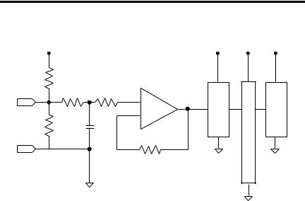
Simplified Input Circuit Diagram
VLOCAL |
VLOCAL |
VLOCAL |
VLOCAL |
10 M |
|
|
|
200 |
20 K |
M |
|
IN+ |
+ |
u |
|
|
Gain |
l |
A/D |
|
- |
t |
|
249 |
0.1 μF |
i |
|
|
|
p |
|
|
|
l |
|
COM |
|
e |
|
|
20 K |
x |
|
|
e |
|
|
|
|
|
|
|
|
r |
|
Install the 1769-IF16C Module
Follow these steps to install the module.
1.Add the module to the 1769 system.
You can add the module before or after mounting.
2.Mount Expansion I/O.
•Panel mount
•DIN-rail mount
3.Make field wiring connections.
4.Configure the module.
This publication describes these steps in detail.
Adding the Module to the 1769 System
Attach the module to the controller or an adjacent I/O module before or after mounting. For mounting instructions, see Use the Dimensional Template, or Mount the Module to a DIN Rail. To work with a system that is already mounted, see Replace a Single Module Within a System.
Publication 1769-IN085A-EN-P - August 2008
Compact High-density Analog Current Input Module 7
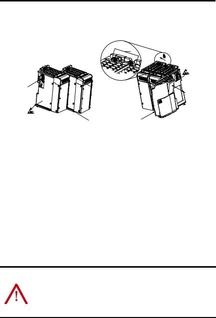
Assemble the 1769 System
The following procedure shows you how to assemble the Compact I/O system.
3
4
2 |
1 |
1 |
5 |
1.Disconnect power.
2.Check that the bus lever of the module to be installed is in the unlocked (fully right) position.
3.Use the upper and lower tongue-and-groove slots (1) to secure the modules together or to a controller.
4.Move the module back along the tongue-and-groove slots until the bus connectors (2) line up with each other.
5.Push the bus lever back slightly to clear the positioning tab (3). Use your fingers or a small screwdriver.
6.To allow communication between the controller and module, move the bus lever fully to the left (4) until it clicks, making sure it is locked firmly in place.
ATTENTION |
When attaching I/O modules, it is very important that the bus connectors |
|||
are securely locked together to be sure of proper electrical connection. |
||||
|
|
|
||
|
|
|
||
|
|
|
Securely locking together the bus connectors is required for use in |
|
|
|
|
hazardous locations. |
|
|
|
|
|
|
For more information on hazardous locations see page 4.
7.Attach an end-cap terminator (5) to the last module in the system by using the tongue-and-groove slots as before.
Publication 1769-IN085A-EN-P - August 2008

8 Compact High-density Analog Current Input Module
8. Lock the end-cap bus terminator (6).
IMPORTANT |
You must use a 1769-ECR or 1769-ECL right or left end cap to terminate |
|
the end of the serial communication bus. An I/O configuration fault will |
|
|
|
occur if an end cap is not used. |
|
|
Replace a Single Module Within a System
The module can be replaced while the system is mounted to a panel or DIN rail.
1.Remove power.
See Remove Power on page 3.
2.Remove the upper and lower mounting screws from the module or open the DIN latches using a flat-blade or Phillips screwdriver.
3.Move the bus lever to the right to disconnect or unlock the bus.
4.On the right-side adjacent module, move its bus lever to the right (unlock) to disconnect it from the module to be removed.
5.Gently slide the disconnected module forward.
If you feel excessive resistance, check that the module is disconnected from the bus and that both mounting screws are removed or DIN latches opened.
TIP |
It may be necessary to rock the module slightly from front to back |
|
to remove it, or, in a panel-mounted system, to loosen the screws |
|
|
|
of adjacent modules. |
6.Be sure that the bus lever on the module and on the right-side adjacent module are in the unlocked (fully right) position before installing the replacement module.
7.Slide the replacement module into the open slot.
8.Connect the modules by locking (fully left) the bus levers on the replacement module and the right-side adjacent module.
9.Replace the mounting screws or snap the module onto the DIN rail.
Publication 1769-IN085A-EN-P - August 2008
Compact High-density Analog Current Input Module 9
Mounting Expansion I/O
ATTENTION |
During panel or DIN rail mounting of all devices, be sure that all debris, |
|||
that is, metal chips or wire strands, is kept from falling into the module. |
||||
|
|
|
||
|
|
|
||
|
|
|
Debris that falls into the module could cause damage when cycling |
|
|
|
|
power. |
|
|
|
|
|
|
|
|
|
|
|
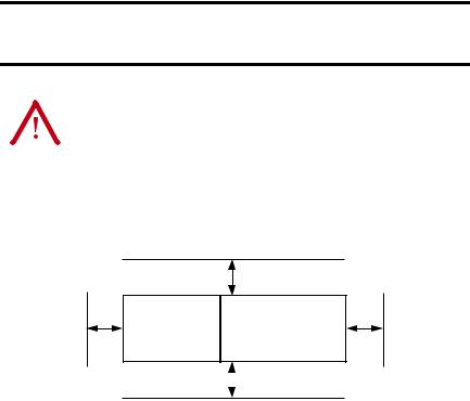
Minimum Spacing
Maintain spacing from enclosure walls, wireways, or adjacent equipment. Allow 50 mm (2 in.) of space on all sides for adequate ventilation, as shown.
Side Controller
Top
Compact I/O |
|
Compact I/O |
|
Compact I/O |
Compact I/O |
Compact I/O |
End Cap |
|
|
|
|
|
|
|
|
|
Bottom |
|
|
|
|
||
|
|
|
|
|
|||
|
|
|
|
|
|
|
|
Side
Mount the Module to a Panel
Mount the module to a panel using two screws per module. Use M4 or #8 panhead screws. Mounting screws are required on every module.
Publication 1769-IN085A-EN-P - August 2008
Loading...