


 Loading...
MicroLogix™ 1500
Programmable
Controllers
Bulletin 1764
User Manual

Important User Information Because of the variety of uses for the products described in this publication, those responsible for the application and use of this
control equipment must satisfy themselves that all necessary steps have been taken to assure that each application and use meets all performance and safety requirements, including any applicable laws, regulations, codes and standards.
The illustrations, charts, sample programs and layout examples shown in this guide are intended solely for purposes of example. Since there are many variables and requirements associated with any particular installation, Allen-Bradley does not assume responsibility or liability (to include intellectual property liability) for actual use based upon the examples shown in this publication.
Allen-Bradley publication SGI-1.1, Safety Guidelines for the Application, Installation and Maintenance of Solid-State Control
(available from your local Allen-Bradley office), describes some important differences between solid-state equipment and electromechanical devices that should be taken into consideration when applying products such as those described in this publication.
Reproduction of the contents of this copyrighted publication, in whole or part, without written permission of Rockwell Automation, is prohibited.
Throughout this publication, notes may be used to make you aware of safety considerations. The following annotations and their accompanying statements help you to identify a potential hazard, avoid a potential hazard, and recognize the consequences of a potential hazard:
WARNING
!
Identifies information about practices or circumstances that can cause an explosion in a hazardous environment, which may lead to personal injury or death, property damage, or economic loss.
ATTENTION |
Identifies information about practices or |
|
circumstances that can lead to personal injury or |
||
|
||
|
death, property damage, or economic loss. |
!
IMPORTANT |
Identifies information that is critical for successful |
|
application and understanding of the product. |
||
|
||
|
||
|
|
MicroLogix, Compact I/O, and RSLogix are trademarks of Rockwell Automation.

Summary of Changes
The information below summarizes the changes to this manual since the last printing.
To help you find new and updated information in this release of the manual, we have included change bars as shown to the right of this paragraph.
The table below lists the sections that document new features and additional or updated information on existing features.
For this information: |
See |
|
|
|
|
Series C support for up to 16 expansion I/O |
Chapter 1 |
|
modules |
|
|
|
|
|
List of controller series, OS FRN numbers, |
Page |
1-5 |
and RSLogix versions |
|
|
|
|
|
Updated list of recommended surge |
Page |
3-6 |
suppressors |
|
|
|
|
|
Ethernet Connectivity |
Page |
4-23 |
|
|
|
Typical CPU hold-up time |
Page A-1 |
|
|
|
|
Updated system loading and heat |
Appendix F |
|
dissipation worksheets |
|
|
|
|
|
System loading graphs for 1769 power |
pages F-5 through F-7 |
|
supplies, including 1769-PA4 and 1769-PB4 |
|
|
|
|
|
Publication 1764-UM001B-EN-P - March 2002
Summary of Changes |
iv |
|
|
Publication 1764-UM001B-EN-P - March 2002
|
Table of Contents |
|
|
Preface |
|
|
Who Should Use this Manual. . . . . . . . . . . . . . . . . . . . . . . |
P-1 |
|
Purpose of this Manual . . . . . . . . . . . . . . . . . . . . . . . . . . . |
P-1 |
|
Related Documentation . . . . . . . . . . . . . . . . . . . . . . . . . . . |
P-1 |
|
Common Techniques Used in this Manual . . . . . . . . . . . . . |
P-3 |
|
Rockwell Automation Support . . . . . . . . . . . . . . . . . . . . . . |
P-3 |
|
Local Product Support . . . . . . . . . . . . . . . . . . . . . . . . . |
P-3 |
|
Technical Product Assistance . . . . . . . . . . . . . . . . . . . . |
P-3 |
|
Your Questions or Comments on this Manual . . . . . . . . |
P-4 |
|
Chapter 1 |
|
Hardware Overview |
Hardware Features . . . . . . . . . . . . . . . . . . . . . . . . . . . . . . |
1-1 |
|
MicroLogix 1500 Component Descriptions . . . . . . . . . . . . . |
1-2 |
|
Base Units . . . . . . . . . . . . . . . . . . . . . . . . . . . . . . . . . . |
1-2 |
|
Processors . . . . . . . . . . . . . . . . . . . . . . . . . . . . . . . . . . |
1-3 |
|
Data Access Tool (Catalog Number 1764-DAT) . . . . . . . |
1-3 |
|
Memory Modules/Real-Time Clock . . . . . . . . . . . . . . . . |
1-4 |
|
Cables . . . . . . . . . . . . . . . . . . . . . . . . . . . . . . . . . . . . . |
1-4 |
|
Programming . . . . . . . . . . . . . . . . . . . . . . . . . . . . . . . . . . |
1-5 |
|
Communication Options . . . . . . . . . . . . . . . . . . . . . . . . . . |
1-6 |
|
Compact™ Expansion I/O . . . . . . . . . . . . . . . . . . . . . . . . . |
1-6 |
|
End Cap . . . . . . . . . . . . . . . . . . . . . . . . . . . . . . . . . . . |
1-6 |
|
Expansion Power Supply and Cables . . . . . . . . . . . . . . |
1-7 |
|
System Requirements for Using Expansion Modules . . . |
1-7 |
|
Adding an I/O Bank . . . . . . . . . . . . . . . . . . . . . . . . . . |
1-9 |
|
Addressing Expansion I/O . . . . . . . . . . . . . . . . . . . . . . |
1-11 |
|
Expansion I/O Power Failure . . . . . . . . . . . . . . . . . . . . |
1-11 |
|
Chapter 2 |
|
Installing Your Controller |
Agency Certifications. . . . . . . . . . . . . . . . . . . . . . . . . . . . . |
2-1 |
|
Compliance to European Union Directives . . . . . . . . . . . . . |
2-1 |
|
EMC Directive . . . . . . . . . . . . . . . . . . . . . . . . . . . . . . . |
2-1 |
|
Low Voltage Directive . . . . . . . . . . . . . . . . . . . . . . . . . |
2-2 |
|
Installation Considerations. . . . . . . . . . . . . . . . . . . . . . . . . |
2-2 |
|
Safety Considerations . . . . . . . . . . . . . . . . . . . . . . . . . . . . |
2-3 |
|
Hazardous Location Considerations . . . . . . . . . . . . . . . |
2-3 |
|
Disconnecting Main Power. . . . . . . . . . . . . . . . . . . . . . |
2-4 |
|
Safety Circuits . . . . . . . . . . . . . . . . . . . . . . . . . . . . . . . |
2-4 |
|
Power Distribution. . . . . . . . . . . . . . . . . . . . . . . . . . . . |
2-5 |
|
Periodic Tests of Master Control Relay Circuit . . . . . . . . |
2-5 |
|
Power Considerations . . . . . . . . . . . . . . . . . . . . . . . . . . . . |
2-5 |
|
Isolation Transformers . . . . . . . . . . . . . . . . . . . . . . . . . |
2-5 |
|
Power Supply Inrush . . . . . . . . . . . . . . . . . . . . . . . . . . |
2-6 |
|
Loss of Power Source. . . . . . . . . . . . . . . . . . . . . . . . . . |
2-6 |
Publication 1764-UM001B-EN-P - April 2002

Table of Contents vi
|
Input States on Power Down . . . . . . . . . . . . . . . . . . . . |
2-6 |
|
Other Types of Line Conditions . . . . . . . . . . . . . . . . . . |
2-7 |
|
Preventing Excessive Heat . . . . . . . . . . . . . . . . . . . . . . . . . |
2-7 |
|
Master Control Relay . . . . . . . . . . . . . . . . . . . . . . . . . . . . . |
2-8 |
|
Using Emergency-Stop Switches . . . . . . . . . . . . . . . . . . |
2-9 |
|
Schematic (Using IEC Symbols) . . . . . . . . . . . . . . . . . . |
2-10 |
|
Schematic (Using ANSI/CSA Symbols). . . . . . . . . . . . . . |
2-11 |
|
Base Unit Mounting Dimensions . . . . . . . . . . . . . . . . . . . . |
2-12 |
|
Controller Spacing. . . . . . . . . . . . . . . . . . . . . . . . . . . . . . . |
2-12 |
|
Mounting the Controller . . . . . . . . . . . . . . . . . . . . . . . . . . |
2-13 |
|
Using a DIN Rail . . . . . . . . . . . . . . . . . . . . . . . . . . . . . |
2-14 |
|
Base Unit Panel Mounting . . . . . . . . . . . . . . . . . . . . . . |
2-16 |
|
Installing Controller Components. . . . . . . . . . . . . . . . . . . . |
2-17 |
|
Prevent Electrostatic Discharge . . . . . . . . . . . . . . . . . . . |
2-17 |
|
Processor. . . . . . . . . . . . . . . . . . . . . . . . . . . . . . . . . . . |
2-17 |
|
Data Access Tool (DAT). . . . . . . . . . . . . . . . . . . . . . . . |
2-19 |
|
Memory Module/Real-Time Clock. . . . . . . . . . . . . . . . . |
2-20 |
|
Compact I/O . . . . . . . . . . . . . . . . . . . . . . . . . . . . . . . . |
2-22 |
|
Chapter 3 |
|
Wiring Your Controller |
Wiring Requirements. . . . . . . . . . . . . . . . . . . . . . . . . . . . . |
3-1 |
|
Wiring Recommendation . . . . . . . . . . . . . . . . . . . . . . . |
3-2 |
|
Using Surge Suppressors . . . . . . . . . . . . . . . . . . . . . . . . . . |
3-4 |
|
Recommended Surge Suppressors . . . . . . . . . . . . . . . . |
3-6 |
|
Grounding the Controller . . . . . . . . . . . . . . . . . . . . . . . . . |
3-6 |
|
Wiring Diagrams . . . . . . . . . . . . . . . . . . . . . . . . . . . . . . . . |
3-8 |
|
Miswiring - 1764-28BXB Only. . . . . . . . . . . . . . . . . . . . |
3-8 |
|
Terminal Block Layouts . . . . . . . . . . . . . . . . . . . . . . . . |
3-9 |
|
Terminal Groupings . . . . . . . . . . . . . . . . . . . . . . . . . . . |
3-10 |
|
Sinking and Sourcing Input Circuits . . . . . . . . . . . . . . . . . . |
3-10 |
|
1764-24AWA Wiring Diagram . . . . . . . . . . . . . . . . . . . . |
3-11 |
|
1764-24BWA Wiring Diagram with Sinking Inputs . . . . . |
3-12 |
|
1764-24BWA Wiring Diagram with Sourcing Inputs . . . . |
3-13 |
|
1764-28BXB Wiring Diagram with Sinking Inputs . . . . . 3-14 |
|
|
1764-28BXB Wiring Diagram with Sourcing Outputs . . . |
3-15 |
|
Controller I/O Wiring . . . . . . . . . . . . . . . . . . . . . . . . . . . . |
3-16 |
|
Minimizing Electrical Noise. . . . . . . . . . . . . . . . . . . . . . |
3-16 |
|
Transistor Output Transient Pulses . . . . . . . . . . . . . . . . |
3-16 |
|
Chapter 4 |
|
Communication Connections |
Default Communication Configuration . . . . . . . . . . . . . . . . |
4-1 |
|
Communications Toggle Push Button. . . . . . . . . . . . . . . . . |
4-2 |
|
Connecting to the RS-232 Port . . . . . . . . . . . . . . . . . . . . . . |
4-3 |
|
DF1 Full-Duplex Communication Parameters . . . . . . . . |
4-3 |
|
Making a DF1 Full-Duplex Point-to-Point Connection . . |
4-3 |
Publication 1764-UM001B-EN-P - April 2002
Table of Contents |
vii |
|
|
Using Trim Pots and the Data
Access Tool (DAT)
Using Real-Time Clock and
Memory Modules
Using a Modem . . . . . . . . . . . . . . . . . . . . . . . . . . . . . . 4-5 Isolated Modem Connection. . . . . . . . . . . . . . . . . . . . . 4-5 Connecting to a DF1 Half-Duplex Network . . . . . . . . . . 4-7 Connecting to a DH-485 Network . . . . . . . . . . . . . . . . . . . 4-10 DH-485 Configuration Parameters. . . . . . . . . . . . . . . . . 4-12 Recommended Tools . . . . . . . . . . . . . . . . . . . . . . . . . . 4-12 DH-485 Communication Cable . . . . . . . . . . . . . . . . . . . 4-12
Communication Cable Connection to the
DH-485 Connector . . . . . . . . . . . . . . . . . . . . . . . . . . . . 4-13 Connecting the AIC+ . . . . . . . . . . . . . . . . . . . . . . . . . . 4-15 Connecting to DeviceNet . . . . . . . . . . . . . . . . . . . . . . . . . 4-22 Cable Selection Guide . . . . . . . . . . . . . . . . . . . . . . . . . 4-22 Connecting to Ethernet . . . . . . . . . . . . . . . . . . . . . . . . . . . 4-23 Ethernet Connections . . . . . . . . . . . . . . . . . . . . . . . . . . 4-23 RS-232 Connections . . . . . . . . . . . . . . . . . . . . . . . . . . . 4-24
Chapter 5
Trim Pot Operation . . . . . . . . . . . . . . . . . . . . . . . . . . . . . . 5-1
Trim Pot Information Function File . . . . . . . . . . . . . . . . 5-2
Error Conditions . . . . . . . . . . . . . . . . . . . . . . . . . . . . . 5-2
Data Access Tool (DAT) . . . . . . . . . . . . . . . . . . . . . . . . . . 5-2
DAT Keypad and Indicator Light Functions . . . . . . . . . . 5-2
Power-Up Operation . . . . . . . . . . . . . . . . . . . . . . . . . . 5-3
DAT Function File . . . . . . . . . . . . . . . . . . . . . . . . . . . . 5-4
Power Save Timeout (PST) Parameter . . . . . . . . . . . . . . 5-4
Understanding the DAT Display . . . . . . . . . . . . . . . . . . 5-5
Entering Bit Mode . . . . . . . . . . . . . . . . . . . . . . . . . . . . 5-6
Entering Integer Mode . . . . . . . . . . . . . . . . . . . . . . . . . 5-6
Monitoring and Editing. . . . . . . . . . . . . . . . . . . . . . . . . 5-6
F1 and F2 Functions. . . . . . . . . . . . . . . . . . . . . . . . . . . 5-7
Working Screen Operation . . . . . . . . . . . . . . . . . . . . . . 5-7
Non-Existent Elements . . . . . . . . . . . . . . . . . . . . . . . . . 5-8
Controller Faults . . . . . . . . . . . . . . . . . . . . . . . . . . . . . 5-8
Error Conditions . . . . . . . . . . . . . . . . . . . . . . . . . . . . . 5-9
Chapter 6
Real-Time Clock Operation . . . . . . . . . . . . . . . . . . . . . . . . 6-1 Removal/Insertion Under Power. . . . . . . . . . . . . . . . . . 6-1 Real-Time Clock Function File . . . . . . . . . . . . . . . . . . . 6-1 Accuracy . . . . . . . . . . . . . . . . . . . . . . . . . . . . . . . . . . . 6-2 Writing Data to the Real-Time Clock. . . . . . . . . . . . . . . 6-2 RTC Battery Operation . . . . . . . . . . . . . . . . . . . . . . . . . 6-2
Memory Module Operation . . . . . . . . . . . . . . . . . . . . . . . . 6-3 User Program and Data Back-Up . . . . . . . . . . . . . . . . . 6-3 Program Compare . . . . . . . . . . . . . . . . . . . . . . . . . . . . 6-4
Publication 1764-UM001B-EN-P - April 2002

Table of Contents viii
|
Data File Download Protection. . . . . . . . . . . . . . |
. . . . . 6-4 |
|
Memory Module Write Protection . . . . . . . . . . . . |
. . . . . 6-5 |
|
Removal/Insertion Under Power. . . . . . . . . . . . . |
. . . . . 6-5 |
|
Memory Module Information File . . . . . . . . . . . . |
. . . . . 6-5 |
|
Appendix A |
|
Specifications |
Controller Specifications . . . . . . . . . . . . . . . . . . . . . |
. . . . . A-1 |
|
Choosing a Power Supply . . . . . . . . . . . . . . . . . |
. . . . . A-2 |
|
Transistor Output Transient Pulses . . . . . . . . . . . |
. . . . . A-8 |
|
Controller Dimensions. . . . . . . . . . . . . . . . . . . . . . . |
. . . . . A-9 |
|
Compact I/O Dimensions . . . . . . . . . . . . . . . . . . . . |
. . . . . A-9 |
|
Panel Mounting . . . . . . . . . . . . . . . . . . . . . . . . . |
. . . . . A-9 |
|
End Cap . . . . . . . . . . . . . . . . . . . . . . . . . . . . . . |
. . . . A-10 |
|
Appendix B |
|
Replacement Parts |
MicroLogix 1500 Replacement Kits. . . . . . . . . . . . . . |
. . . . . B-1 |
|
Lithium Battery (1747-BA) . . . . . . . . . . . . . . . . . . . |
. . . . . B-2 |
|
Installing . . . . . . . . . . . . . . . . . . . . . . . . . . . . . . |
. . . . . B-2 |
|
Battery Handling . . . . . . . . . . . . . . . . . . . . . . . . |
. . . . . B-3 |
|
Storing . . . . . . . . . . . . . . . . . . . . . . . . . . . . . . . |
. . . . . B-3 |
|
Transporting . . . . . . . . . . . . . . . . . . . . . . . . . . . |
. . . . . B-3 |
|
Disposing . . . . . . . . . . . . . . . . . . . . . . . . . . . . . |
. . . . . B-4 |
|
Replacement Terminal Blocks . . . . . . . . . . . . . . . . . |
. . . . . B-5 |
|
Replacement Doors. . . . . . . . . . . . . . . . . . . . . . . . . |
. . . . . B-6 |
|
Base Terminal Door (1764-RPL-TDR1) . . . . . . . . |
. . . . . B-6 |
|
Processor Access Door (1764-RPL-CDR1) . . . . . . |
. . . . . B-6 |
|
Base Comms Door |
|
|
(included in 1764-RPL-DR) . . . . . . . . . . . . . . . . . |
. . . . . B-6 |
|
Trim Pots/Mode Switch Cover Door |
|
|
(included in 1764-RPL-DR) . . . . . . . . . . . . . . . . . |
. . . . . B-6 |
|
Appendix C |
|
Troubleshooting Your System |
Understanding Controller LEDs . . . . . . . . . . . . . . . . |
. . . . . C-1 |
|
When Operating Normally . . . . . . . . . . . . . . . . . |
. . . . . C-2 |
|
When an Error Exists . . . . . . . . . . . . . . . . . . . . . |
. . . . . C-2 |
|
Controller Error Recovery Model . . . . . . . . . . . . . . . |
. . . . . C-3 |
|
Identifying Controller Faults . . . . . . . . . . . . . . . . . . |
. . . . . C-4 |
|
Automatically Clearing Faults . . . . . . . . . . . . . . . |
. . . . . C-4 |
|
Manually Clearing Faults Using the Fault Routine |
. . . . . C-4 |
|
Fault Messages. . . . . . . . . . . . . . . . . . . . . . . . . . |
. . . . . C-5 |
|
Calling Rockwell Automation for Assistance . . . . . . . |
. . . . . C-5 |
Publication 1764-UM001B-EN-P - April 2002
Table of Contents |
ix |
|
|
Upgrading Your Operating System
Understanding Communication
Protocols
System Loading and Heat
Dissipation
Appendix D
Preparing for Upgrade. . . . . . . . . . . . . . . . . . . . . . . . . . . . D-1 Performing the Upgrade . . . . . . . . . . . . . . . . . . . . . . . . . . D-2 Missing/Corrupt OS LED Pattern . . . . . . . . . . . . . . . . . . . . D-2
Appendix E
RS-232 Communication Interface . . . . . . . . . . . . . . . . . . . . E-1 DF1 Full-Duplex Protocol . . . . . . . . . . . . . . . . . . . . . . . . . E-1 DF1 Half-Duplex Protocol . . . . . . . . . . . . . . . . . . . . . . . . . E-2 DF1 Half-Duplex Operation . . . . . . . . . . . . . . . . . . . . . E-2
Considerations When Communicating as a DF1 Slave
on a Multi-drop Link . . . . . . . . . . . . . . . . . . . . . . . . . . E-3 Using Modems with MicroLogix 1500
Programmable Controllers . . . . . . . . . . . . . . . . . . . . . . . . . E-3 Dial-Up Phone Modems . . . . . . . . . . . . . . . . . . . . . . . . E-4 Leased-Line Modems . . . . . . . . . . . . . . . . . . . . . . . . . . E-4 Radio Modems. . . . . . . . . . . . . . . . . . . . . . . . . . . . . . . E-5 Line Drivers. . . . . . . . . . . . . . . . . . . . . . . . . . . . . . . . . E-5
DH-485 Communication Protocol. . . . . . . . . . . . . . . . . . . . E-5 DH-485 Network Description . . . . . . . . . . . . . . . . . . . . E-5 DH-485 Token Rotation . . . . . . . . . . . . . . . . . . . . . . . . E-6 DH-485 Configuration Parameters. . . . . . . . . . . . . . . . . E-6 Devices that Use the DH-485 Network . . . . . . . . . . . . . E-7 Important DH-485 Network Planning Considerations. . . E-8
Modbus RTU Slave Communication Protocol (MicroLogix 1764-LSP and 1764-LRP Series B and
later processors only) . . . . . . . . . . . . . . . . . . . . . . . . . . . E-13 ASCII Protocol (MicroLogix 1500 1764-LSP
and 1764-LRP Series B and later Processors only) . . . . . . . E-13
Appendix F
System Loading Limitations . . . . . . . . . . . . . . . . . . . . . . . . F-1
System Expansion Calculations . . . . . . . . . . . . . . . . . . . . . F-1
Selecting System Devices . . . . . . . . . . . . . . . . . . . . . . . F-2
Verifying the System Loading . . . . . . . . . . . . . . . . . . . . F-4
Calculating Heat Dissipation . . . . . . . . . . . . . . . . . . . . . . . F-9
Glossary
Index
Publication 1764-UM001B-EN-P - April 2002
Table of Contents |
x |
|
|
Publication 1764-UM001B-EN-P - April 2002
Preface
Who Should Use this Manual
Purpose of this Manual
Related Documentation
Read this preface to familiarize yourself with the rest of the manual. It provides information concerning:
•who should use this manual
•the purpose of this manual
•related documentation
•conventions used in this manual
•Rockwell Automation support
Use this manual if you are responsible for designing, installing, programming, or troubleshooting control systems that use MicroLogix 1500 controllers.
You should have a basic understanding of electrical circuitry and familiarity with relay logic. If you do not, obtain the proper training before using this product.
This manual is a reference guide for MicroLogix 1500 controllers. It describes the procedures you use to install, wire, and troubleshoot your controller. This manual:
•explains how to install and wire your controllers
•gives you an overview of the MicroLogix 1500 controller system
Refer to publication 1762-RM001, MicroLogix 1200 and MicroLogix 1500 Programmable Controllers Instruction Set Reference Manual for the MicroLogix 1200 and 1500 instruction set and for application examples to show the instruction set in use. Refer to your programming software user documentation for more information on programming your MicroLogix 1500 controller.
The documents listed on page P-2 contain additional information concerning Rockwell Automation products. If you would like a copy, you can:
•download a free electronic version from the internet: www.ab.com/micrologix or www.theautomationbookstore.com
•purchase a printed manual by:
–contacting your local distributor or Rockwell Automation representative
–visiting www.theautomationbookstore.com and placing your order
–calling 1.800.963.9548 (USA/Canada)
or 001.330.725.1574 (Outside USA/Canada)
Publication 1764-UM001B-EN-P - April 2002

Preface P-2
|
|
For |
Read this Document |
Document Number |
|
|
|
|
|
|
|
A technical overview of the MicroLogix 1500 and related |
MicroLogix 1500 Programmable Controllers |
1764-TD001 |
|
|
|||
|
|
products |
Technical Data |
|
|
|
|
|
|
|
|
Information on the MicroLogix 1500 Controllers instruction set |
MicroLogix 1200 and 1500 Programmable |
1762-RM001 |
|
|
|||
|
|
|
Controllers Instruction Set Reference Manual |
|
|
|
|
|
|
|
|
Information on mounting and wiring the MicroLogix 1500 Base |
MicroLogix 1500 Programmable Controllers |
1764-IN001 |
|
|
Units, including a mounting template for easy installation |
Base Unit Installation Instructions |
|
|
|
|
|
|
|
|
An overview of Compact I/O |
Compact I/O System Overview |
1769-SO001 |
|
|
|||
|
|
|
|
|
|
|
More information on Compact I/O Power Supplies and Cables |
1769 Compact I/O Power Supplies and |
1769-TD001 |
|
|
|||
|
|
|
Communication Bus Expansion Cables |
|
|
|
|
Technical Data |
|
|
|
|
|
|
|
|
More information on Compact Analog I/O and Temperature Input |
Compact Analog I/O and Temperature Input |
1769-TD004 |
|
|
|||
|
|
Modules |
Modules Technical Data |
|
|
|
|
|
|
|
|
Detailed information on using Compact I/O Analog Modules |
Compact I/O Analog Modules User Manual |
1769-UM002 |
|
|
|||
|
|
|
|
|
|
|
Detailed information on installing, configuring, and using |
Compact I/O 1769-IT6 Thermocouple/mV |
1769-UM004 |
|
|
|||
|
|
1769-IT6 Thermocouple/mV Input Modules |
Input Module User Manual |
|
|
|
|
|
|
|
|
Detailed information on installing, configuring, and using |
Compact I/O 1769-IR6 RTD/Resistance Input |
1769-UM005 |
|
|
|||
|
|
1769-IR6 RTD/Resistance Input Modules |
Module User Manual |
|
|
|
|
|
|
|
|
Detailed information on installing, configuring, and using |
Compact 1769-HSC High Speed Counter |
1769-UM006 |
|
|
|||
|
|
1769-HSC High Speed Counter Modules |
Module User Manual |
|
|
|
|
|
|
|
|
A description on how to install and connect an AIC+. This |
Advanced Interface Converter (AIC+) User |
1761-6.4 |
|
|
manual also contains information on network wiring. |
Manual |
|
|
|
|
|
|
|
|
Information on how to install, configure, and commission a DNI |
DeviceNet™ Interface User Manual |
1761-6.5 |
|
|
|
|
|
|
|
Information on installing, connecting, and configuring an ENI |
Ethernet Interface User Manual |
1761-UM001 |
|
|
|||
|
|
|
|
|
|
|
Information on installing, configuring, and using a DeviceNet |
Compact™ I/O 1769-SDN DeviceNet Scanner |
1761-UM009 |
|
|
|||
|
|
Scanner |
User Manual |
|
|
|
|
|
|
|
|
Information on DF1 open protocol. |
DF1 Protocol and Command Set Reference |
1770-6.5.16 |
|
|
|
Manual |
|
|
|
|
|
|
|
|
In-depth information on grounding and wiring Allen-Bradley |
Allen-Bradley Programmable Controller |
1770-4.1 |
|
|
programmable controllers |
Grounding and Wiring Guidelines |
|
|
|
|
|
|
|
|
A description of important differences between solid-state |
Application Considerations for Solid-State |
SGI-1.1 |
|
|
programmable controller products and hard-wired |
Controls |
|
|
|
electromechanical devices |
|
|
|
|
|
|
|
|
|
An article on wire sizes and types for grounding electrical |
National Electrical Code - Published by the National Fire Protection |
|
|
|
equipment |
Association of Boston, MA. |
|
|
|
|
|
|
|
|
A complete listing of current documentation, including ordering |
Allen-Bradley Publication Index |
SD499 |
|
|
instructions. Also indicates whether the documents are available |
|
|
|
|
on CD-ROM or in multi-languages. |
|
|
|
|
|
|
|
|
|
A glossary of industrial automation terms and abbreviations |
Allen-Bradley Industrial Automation Glossary |
AG-7.1 |
|
|
|
|
|
Publication 1764-UM001B-EN-P - April 2002

Preface P-3
Common Techniques Used in this Manual
Rockwell Automation
Support
The following conventions are used throughout this manual:
•Bulleted lists such as this one provide information, not procedural steps.
•Numbered lists provide sequential steps or hierarchical information.
•Italic type is used for emphasis.
Rockwell Automation offers support services worldwide, with over 75 Sales/Support Offices, 512 authorized Distributors and 260 authorized Systems Integrators located throughout the United States alone, plus Rockwell Automation representatives in every major country in the world.
Local Product Support
Contact your local Rockwell Automation representative for:
•sales and order support
•product technical training
•warranty support
•support service agreements
Technical Product Assistance
Before you contact Rockwell Automation for technical assistance, we suggest you please review the troubleshooting information contained in this publication first.
Publication 1764-UM001B-EN-P - April 2002

Preface P-4
If the problem persists, call your local Rockwell Automation representative or contact Rockwell Automation in one of the following ways:
Phone |
United |
1.440.646.5800 |
|
|
States/Canada |
|
|
|
|
|
|
|
Outside United |
You can access the phone number for your |
|
|
States/Canada |
country via the Internet: |
|
|
|
1. |
Go to http://www.ab.com |
|
|
2. |
Click on Product Support |
|
|
|
(http://support.automation.rockwell.com) |
|
|
3. |
Under Support Centers, click on Contact |
|
|
|
Information |
|
|
|
|
Internet |
|
1. Go to http://www.ab.com |
|
|
|
2. Click on Product Support |
|
|
|
(http://support.automation.rockwell.com) |
|
|
|
|
|
Your Questions or Comments on this Manual
If you find a problem with this manual, or you have any suggestions for how this manual could be made more useful to you, please contact us at the address below:
Rockwell Automation
Automation Control and Information Group
Technical Communication, Dept. A602V
P.O. Box 2086
Milwaukee, WI 53201-2086
or visit our internet page at:
http://www.rockwellautomation.com
For the latest information on MicroLogix controllers, visit www.ab.com/micrologix
Publication 1764-UM001B-EN-P - April 2002

Chapter 1
Hardware Overview
Hardware Features
The MicroLogix 1500 programmable controller is composed of a base unit, which contains a power supply, input and output circuits, and a processor. The controller is available with 24 or 28 points of embedded I/O. Additional I/O may be added using Compact™ I/O.
The hardware features of the controller are:
10 |
1 |
2
REM
RUN PROG
12 |
3 |
|
|
|
|
|
4 |
11 |
|
|
|
5 |
|
|
|
|
|
10 9 |
8 |
1 |
7 |
6 |
Feature |
Description |
Feature |
Description |
|
|
|
|
1 |
Removable Terminal Blocks |
7 |
Memory Module/Real-Time Clock(1) |
2 |
Interface to Expansion I/O, |
8 |
Replacement Battery(1) |
|
Removable ESD Barrier |
|
|
|
|
|
|
3 |
Input LEDs |
9 |
Battery |
|
|
|
|
4 |
Output LEDs |
10 |
Terminal Doors and Label |
|
|
|
|
5 |
Communication Port |
11 |
Data Access Tool(1) |
6 |
Status LEDs |
12 |
Mode Switch, Trim Pots |
|
|
|
|
(1) Optional.
Publication 1764-UM001B-EN-P - April 2002

1-2 Hardware Overview
MicroLogix 1500
Component Descriptions
A controller is composed of a processor (1764-LSP or enhanced 1764-LRP with RS-232 port) and one of the base units listed below. The FET transistor outputs are available on the 1764-28BXB base only.
Base Units
Catalog |
Line Power |
Inputs |
Outputs |
High Speed I/O |
||
Number |
|
|
|
|
|
|
|
|
|
|
|
||
1764-24AWA |
120/240V ac |
(12) 120V ac |
(12) Relay, 2 isolated relays |
n/a |
||
|
|
|
per unit |
|
|
|
|
|
|
|
|
|
|
1764-24BWA |
120/240V ac |
(8) Standard 24V dc |
(12) Relay, 2 isolated relays |
(4) |
20 kHz input |
|
|
|
(4) Fast 24V dc |
per unit |
|
|
|
|
|
|
|
|
|
|
1764-28BXB |
24V dc |
(8) Standard 24V dc |
(6) |
Relay, 2 isolated relays |
(8) |
20 kHz input |
|
|
(8) Fast 24V dc |
per unit |
(2) |
20 kHz output |
|
|
|
|
(4) |
Standard 24V dc FET |
|
|
|
|
|
(2) |
Fast 24V dc FET |
|
|
|
|
|
|
|
|
|
Publication 1764-UM001B-EN-P - April 2002
Hardware Overview |
1-3 |
|
|
Processors
Processor (Catalog Number 1764-LSP)
Processor (Catalog Number 1764-LRP)
Communications Port
• DTE (male) 9-pin D-shell connector
• 30V dc isolation
Data Access Tool (Catalog Number 1764-DAT)
1764-DAT mounted on 1764-LSP processor.
Publication 1764-UM001B-EN-P - April 2002

1-4 Hardware Overview
Memory Modules/Real-Time Clock
Memory module mounted on 1764-LSP processor.
The following memory modules and real-time clock modules are available:
Catalog Number |
Function |
Memory Size |
|
|
|
1764-RTC |
Real-Time Clock |
not applicable |
|
|
|
1764-MM1 |
Memory Module |
8K |
|
|
|
1764-MM1RTC |
Memory Module and Real-Time Clock |
8K |
|
|
|
1764-MM2(1) |
Memory Module |
16K |
1764-MM2RTC(1) |
Memory Module and Real-Time Clock |
16K |
(1) For 1764-LRP programs greater than 8k, use the 1764-MM2 or 1764-MM2RTC.
Cables
Use only the following communication cables in Class I, Division 2 hazardous locations.
Table 1.1 Cables for Use in Class I, Division 2 Hazardous Environment
1761-CBL-PM02 Series C or later |
2707-NC8 Series B or later |
|
|
1761-CBL-HM02 Series C or later |
2707-NC9 Series B or later |
|
|
1761-CBL-AM00 Series C or later |
2707-NC10 Series B or later |
|
|
1761-CBL-AP00 Series C or later |
2707-NC11 Series B or later |
|
|
Publication 1764-UM001B-EN-P - April 2002

Hardware Overview |
1-5 |
|
|
Programming
Programming the MicroLogix 1500 programmable controller is done using RSLogix™ 500, Rev. 4.0 or later. Certain features are only available when using the most current version of the software, as noted in System Requirements for Using Expansion Modules on page 1-7.
The following table lists the firmware release numbers, feature and functionality enhancements, and the required version of RSLogix 500 and RSLogix 500 Starter software.
Table 1.B Required Software Version by FRN Number
Controller |
Firmware |
Available |
Catalog |
Catalog |
OS FRN |
Feature and Functionality |
Required |
|
|
|
|
||||||||
|
Release |
for Sale |
Number |
Number |
Number |
Changes |
Version of |
|
|
|
|
Date |
Series |
Revision |
|
|
RSLogix |
|
|
|
|
|
|
|
|
|
500/RSLogix |
|
|
|
|
|
|
|
|
|
500 Starter |
|
|
|
|
|
|
|
|
|
Software |
|
|
|
Initial |
February |
A |
B |
2 |
Initial Release |
3.01.00 |
|
|
|
|
|
|||||||
|
Release |
1999 |
|
|
|
|
|
|
|
|
Enhancement |
October |
A |
C |
3 |
Power Supply and Expansion Cable |
3.01.00 |
|
|
|
|
|
|||||||
|
|
1999 |
|
|
|
Compatibility |
|
|
|
|
Series B |
March |
B |
A |
4 |
String Data File Type, |
4.00.00 |
|
|
|
|
|
|||||||
|
Release |
2000 |
|
|
|
ASCII Instruction Set, |
|
|
|
|
|
|
|
|
|
Modbus RTU Slave Protocol, |
|
|
|
|
|
|
|
|
|
Ramping (when using PWM outputs), |
|
|
|
|
|
|
|
|
|
Static Data File Protection, |
|
|
|
1764-LSP |
|
|
|
|
|
RTC Messaging |
|
|
|
Enhancement |
October |
B |
B |
5 |
PTO Controlled Stop, |
4.50.00 |
|
|
|
|
|
|
|||||||
|
|
2000 |
|
|
|
Memory Module Program Compare Bit |
|
|
|
|
|
|
|
|
|
Enhancement |
|
|
|
|
Series C |
September |
C |
A |
6 |
Floating Point Data File Support, |
5.10.00 |
|
|
|
|
|
|||||||
|
Release |
2001 |
|
|
|
Programmable Limit Switch (PLS), |
|
|
|
|
|
|
|
|
|
Real Time Clock Adjust (Copy Word), |
|
|
|
|
|
|
|
|
|
Absolute Value, |
|
|
|
|
|
|
|
|
|
Gray Code, |
|
|
|
|
|
|
|
|
|
Recipe, |
|
|
|
|
|
|
|
|
|
Message Instruction Support for |
|
|
|
|
|
|
|
|
|
1769-SDN |
|
|
|
|
Initial |
March |
B |
A |
4 |
Initial Release - Same Functionality as |
4.00.00 |
|
|
|
|
|
|||||||
|
Release |
2000 |
|
|
|
1764-LSP |
|
|
|
|
Enhancement |
October |
B |
B |
5 |
PTO Controlled Stop, |
4.50.00 |
|
|
|
|
|
|||||||
|
|
2000 |
|
|
|
Memory Module Program Compare Bit |
|
|
|
|
|
|
|
|
|
Enhancement |
|
|
|
1764-LRP |
Series C |
September |
C |
A |
6 |
Floating Point Data File Support, |
5.10.00 |
|
|
|
|
||||||||
Release |
2001 |
|
|
|
Programmable Limit Switch (PLS), |
|
|
|
|
|
|
|
|
|
|
|
|||
|
|
|
|
|
|
Real Time Clock Adjust (Copy Word), |
|
|
|
|
|
|
|
|
|
Absolute Value, |
|
|
|
|
|
|
|
|
|
Gray Code, |
|
|
|
|
|
|
|
|
|
Recipe, |
|
|
|
|
|
|
|
|
|
Message Instruction Support for |
|
|
|
|
|
|
|
|
|
1769-SDN |
|
|
|
|
|
|
|
|
|
|
|
|
|
Publication 1764-UM001B-EN-P - April 2002
1-6 Hardware Overview
Communication Options
Compact™ Expansion I/O
The MicroLogix 1500 can be connected to a personal computer. It can also be connected to the DH-485 network using an Advanced Interface Converter (1761-NET-AIC), to an Ethernet network using an Ethernet Interface (1761-NET-ENI), or to a DeviceNet™ network using a DeviceNet Interface (1761-NET-DNI) or through the DeviceNet Scanner module (1769-SDN). The controller can also be connected to Modbus™ SCADA networks as an RTU slave. See Communication Connections on page 4-1 for more information on connecting to the available communication options.
The 1764-LRP processor provides an additional communication port. Each of the communications ports can be independently configured for any supported communication protocol. (Channel 0 is on the base unit and Channel 1 is on the 1764-LRP processor.)
Compact expansion I/O (Bulletin 1769) can be connected to the MicroLogix 1500 Controller. A maximum of either 8 or 16 expansion I/O modules can be used, depending upon your system. See System Requirements for Using Expansion Modules on page 1-7.
See System Loading and Heat Dissipation on page F-1 for more information on system configurations.
End Cap
An end cap terminator (catalog number 1769-ECR or 1769-ECL) must be used at the end of the group of I/O modules attached to the MicroLogix 1500 Controller. The end cap terminator is not provided with the base or processor units. It is required when using expansion I/O.
This illustration shows the right end cap (1769-ECR ). The left end cap (1769-ECL) is shown on page 1-10.
Publication 1764-UM001B-EN-P - April 2002
Hardware Overview |
1-7 |
|
|
Expansion Power Supply and Cables
With Operating System Revision Number (FRN) 3 or higher, you can connect an additional bank of I/O to your controller. Using an expansion power supply increases the system’s capacity for adding expansion I/O modules. The additional I/O bank is connected to the controller via a specially designed cable. The additional I/O bank must include a power supply and an end cap.
TIP |
Depending on the system configuration, each |
|
controller can support up to 16 expansion I/O |
|
|
|
|
|
|
|
|
|
modules. See the System Requirements for Using |
|
|
Expansion Modules below. Also see System |
|
|
Guidelines on page 1-9 for system limitations and |
|
|
illustrations of expansion I/O banks. |
|
System Requirements for Using Expansion Modules
To support a maximum of 8 I/O modules in an additional I/O bank, you must have the following:
Table 1.3 Requirements to Support a Maximum of 8 I/O Modules
Product |
Catalog Number |
|
|
|
|
|
|
|
|
|
|
MicroLogix 1500 |
1764-LSP, Series A, Revision C or higher |
|
|
||
Processor |
1764-LSP, Series B or higher |
|
|
||
|
|
1764-LRP, Series B or higher |
|
|
|
|
|
|
|
|
|
MicroLogix 1500 |
1764-24AWA, Series A or higher |
|
|
||
|
|
||||
Base Unit |
1764-24BWA, Series A or higher |
|
|
||
|
|
1764-28BXB, Series A or higher |
|
|
|
|
|
|
|
|
|
Operating System |
Firmware Revision Number (FRN) 3 or higher(1) |
|
|
||
Version |
|
|
|
|
|
|
|
|
|
|
|
|
|
1764-LSP, Series A |
RSLogix 500, Version 3.01.09 or higher, |
|
|
|
|
|
|
||
|
|
|
|
|
|
Programming |
1764-LSP, Series B |
RSLogix 500, Version 4.00.00 or higher. |
|
|
|
|
|
||||
1764-LRP, Series B |
|
|
|
||
Software |
|
|
|
||
|
|
|
|
||
|
|
1764-LSP, Series C |
RSLogix 500, Version 5.00.00 or higher. |
|
|
|
|
|
|
||
|
|
1764-LRP, Series C |
|
|
|
|
|
|
|
|
|
1 Power Supply |
1769-PA2, 1769-PA4 |
|
|
|
|
|
|
|
|||
(optional) |
1769-PB2, 1769-PB4 |
|
|
|
|
|
|
|
|
|
|
1 Cable (optional) |
1769-CRL1, 1769-CRL3, 1769-CRR1, 1769-CRR3 |
|
|
||
|
|
||||
|
|
|
|
|
|
1 End Cap (required) |
1769-ECL, 1769-ECR |
|
|
|
|
|
|
|
|||
|
|
|
|
|
|
(1) You can check the FRN by looking at word S:59 (Operating System FRN) in the Status File.
Publication 1764-UM001B-EN-P - April 2002

1-8 Hardware Overview
To support a maximum of 16 I/O modules in an additional I/O bank, you must have the following:
Table 1.4 Requirements to Support a Maximum of 16 I/O Modules
|
|
Product |
Catalog Number |
|
|
|
|||
|
|
|
|
|
|
|
MicroLogix 1500 Processor |
1764-LSP, Series C or higher |
|
|
|
|||
|
|
|
|
1764-LRP, Series C or higher |
|
|
|
|
|
|
|
MicroLogix 1500 Base Unit |
1764-24AWA, Series B or higher |
|
|
|
|||
|
|
|
|
1764-24BWA, Series B or higher |
|
|
|
|
1764-28BXB, Series B or higher |
|
|
|
|
|
|
|
Operating System Version |
Firmware Revision Number (FRN) 6 or higher(1) |
|
|
|
|||
|
|
|
|
|
|
|
Programming Software |
RSLogix 500, Version 5.10.00 or higher. |
|
|
|
|||
|
|
|
|
|
|
|
1 |
Power Supply (optional) |
1769-PA2, 1769-PA4, 1769-PB2, 1769-PB4 |
|
|
|||
|
|
|
|
|
|
|
1 |
Cable (optional) |
1769-CRL1, 1769-CRL3, 1769-CRR1, 1769-CRR3 |
|
|
|||
|
|
|
|
|
|
|
1 |
End Cap (required) |
1769-ECL, 1769-ECR |
|
|
|||
|
|
|
|
|
|
|
(1) You can check the FRN by looking at word S:59 (Operating System FRN) in the Status File. |
||
|
|
|
If your processor is at an older revision, you must |
|
|
IMPORTANT |
|
|
|
upgrade the operating system to FRN 3 or higher |
|
|
|
|
|
|
|
|
|
|
|
|
to use an expansion cable and power supply (or to |
|
|
|
FRN 6 or higher to allow up to 16 expansion |
|
|
|
modules). On the Internet, go to |
|
|
|
http://www.ab.com/micrologix to download the |
|
|
|
|
|
|
|
operating system upgrade. Navigate to MicroLogix |
|
|
|
1500 for further instructions and downloads. |
MicroLogix 1500 base units are not field upgradeable from Series A to Series B.
Publication 1764-UM001B-EN-P - April 2002
Hardware Overview |
1-9 |
|
|
Adding an I/O Bank
System Guidelines
A maximum of one 1769 Expansion Cable can be used in a MicroLogix 1500 system, allowing for two banks of I/O modules (one connected directly to the controller, and the other connected via the cable). Each I/O bank requires its own power supply (Bank 1 uses the controller’s embedded power supply).
ATTENTION |
LIMIT OF ONE EXPANSION POWER SUPPLY |
|
|
|
The expansion power supply cannot be connected |
!an expansion cable. Only one power supply (embedded in the base unit or an expansion power supply) may be used on an I/O bank. Exceeding
these limitations may damage the power supply and result in unexpected operation.directly to the controller. It must be connected using
ATTENTION |
REMOVE POWER |
|
|
|
Remove system power before making or breaking |
!cable connector with power applied, an electrical arc may occur. An electrical arc can cause personal injury or property damage by:
•sending an erroneous signal to your system’s field devices, causing unintended machine operation
•causing an explosion in a hazardous environmentcable connections. When you remove or insert a
Electrical arcing causes excessive wear to contacts on both the module and its mating connector.
Refer to your power supply and I/O module’s documentation for instructions on how to set up your system.
|
See the System Requirements for Using Expansion |
|
IMPORTANT |
||
Modules on page 1-7 to determine the maximum |
||
|
||
|
||
|
number of expansion I/O modules you can use in |
|
|
your MicroLogix system. |
Also see System Loading and Heat Dissipation on page F-1 for more information on system configurations.
Publication 1764-UM001B-EN-P - April 2002

1-10 Hardware Overview
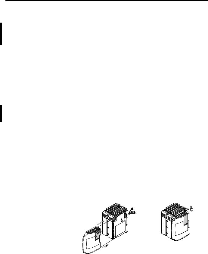
The following illustrations show a MicroLogix 1500 with an expansion I/O bank.
Vertical Orientation
Expansion
I/O Bank 1
1769-CRRx(1) Expansion Cable
Expansion
I/O Bank 2
1769-ECL
End Cap
(1)The x in this catalog number can be either a 1 or a 3 representing the length of the cable: 1 = 1 foot (305 mm) and 3 = 3.28 feet (1 meter).
Horizontal Orientation
1769-ECR
End Cap
Expansion |
1769-CRLx(1) |
Expansion |
I/O Bank 1 |
I/O Bank 2 |
|
|
Expansion Cable |
|
(1)The x in this catalog number can be either a 1 or a 3 representing the length of the cable: 1 = 1 foot (305 mm) and 3 = 3.28 feet (1 meter).
Publication 1764-UM001B-EN-P - April 2002

Hardware Overview |
1-11 |
|
|
Addressing Expansion I/O
The expansion I/O is addressed as slots 1 through 16 (the controller’s embedded I/O is addressed as slot 0). Power supplies and cables are not counted as slots. Modules are counted from left to right on each bank as shown in the illustrations below. For more information on addressing, refer to the MicroLogix 1200 and MicroLogix 1500 Programmable Controllers Instruction Set Reference Manual, publication 1762-RM001.
Vertical Orientation
Embedded
I/O = Slot 0
Slot 3
Slot 1 |
Slot 2 |
Slot 4 |
Slot 5 |
Expansion
I/O Bank 1
Expansion
I/O Bank 2
Horizontal Orientation
Embedded
I/O = Slot 0
Slot 1 |
Slot 2 |
Slot 3 |
Slot 4 |
Slot 5 |
Expansion I/O Bank 1 |
|
Expansion I/O Bank 2 |
|
|
Expansion I/O Power Failure
Expansion I/O errors represent failures of the I/O bus or the modules themselves. The error codes are listed in the MicroLogix 1200 and MicroLogix 1500 Programmable Controllers Instruction Set Reference Manual, publication 1762-RM001.
Publication 1764-UM001B-EN-P - April 2002

1-12 Hardware Overview
Publication 1764-UM001B-EN-P - April 2002

Chapter 2
Installing Your Controller
Agency Certifications
This chapter shows you how to install your controller system. The only tools you require are a Flat or Phillips head screwdriver and drill. Topics include:
•agency certifications
•compliance to European Union Directives
•using in hazardous locations
•master control relay
•power considerations
•preventing excessive heat
•controller spacing
•mounting the controller
•UL 508
•C-UL under CSA C22.2 no. 142
•Class I, Division 2, Groups A, B, C, D (UL 1604, C-UL under CSA C22.2 no. 213)
•CE compliant for all applicable directives
Compliance to European Union Directives
This product has the CE mark and is approved for installation within the European Union and EEA regions. It has been designed and tested to meet the following directives.
EMC Directive
This product is tested to meet Council Directive 89/336/EEC Electromagnetic Compatibility (EMC) and the following standards, in whole or in part, documented in a technical construction file:
•EN 50081-2
EMC - Generic Emission Standard, Part 2 - Industrial Environment
•EN 50082-2
EMC - Generic Immunity Standard, Part 2 - Industrial Environment
This product is intended for use in an industrial environment.
Publication 1764-UM001B-EN-P - April 2002
2-2 Installing Your Controller
Low Voltage Directive
This product is tested to meet Council Directive 73/23/EEC Low
Voltage, by applying the safety requirements of EN 61131-2
Programmable Controllers, Part 2 - Equipment Requirements and
Tests.
For specific information required by EN 61131-2, see the appropriate sections in this publication, as well as the following Allen-Bradley publications:
•Industrial Automation Wiring and Grounding Guidelines for Noise Immunity, publication 1770-4.1
•Guidelines for Handling Lithium Batteries, publication AG-5.4
•Automation Systems Catalog, publication B111
Installation Considerations Most applications require installation in an industrial enclosure (Pollution Degree 2(1)) to reduce the effects of electrical interference
(Over Voltage Category II(2)) and environmental exposure. Locate your controller as far as possible from power lines, load lines, and other sources of electrical noise such as hard-contact switches, relays, and AC motor drives. For more information on proper grounding guidelines, see the Industrial Automation Wiring and Grounding Guidelines publication 1770-4.1.
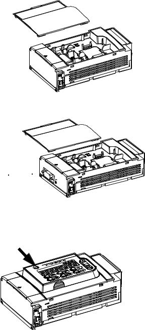
ATTENTION |
Vertical mounting of the controller is not |
|
recommended due to heat build-up considerations. |
||
|
!
ATTENTION
!
Be careful of metal chips when drilling mounting holes for your controller or other equipment within the enclosure or panel. Drilled fragments that fall into the base or processor unit could cause damage. Do not drill holes above a mounted controller if the protective debris strips are removed or the processor is installed.
(1)Pollution Degree 2 is an environment where normally only non-conductive pollution occurs except that occasionally temporary conductivity caused by condensation shall be expected.
(2)Overvoltage Category II is the load level section of the electrical distribution system. At this level transient voltages are controlled and do not exceed the impulse voltage capability of the products insulation.
Publication 1764-UM001B-EN-P - April 2002

Installing Your Controller |
2-3 |
|
|
Safety Considerations
Safety considerations are an important element of proper system installation. Actively thinking about the safety of yourself and others, as well as the condition of your equipment, is of primary importance. We recommend reviewing the following safety considerations.
Hazardous Location Considerations
This equipment is suitable for use in Class I, Division 2, Groups A, B, C, D or non-hazardous locations only. The following WARNING statement applies to use in hazardous locations.
WARNING
!
EXPLOSION HAZARD
•Substitution of components may impair suitability for Class I, Division 2.
•Do not replace components or disconnect equipment unless power has been switched off.
•Do not connect or disconnect components unless power has been switched off, or the area is known to be non-hazardous.
•This product must be installed in an enclosure. All cables connected to the product must remain in the enclosure or be protected by conduit or other means.
•All wiring must comply with N.E.C. article 501-4(b).
WARNING
!
When installing any peripheral device (for example, push buttons, lamps) into a hazardous environment, ensure that they are Class I, Division 2 certified, or determined to be safe for the environment.
Publication 1764-UM001B-EN-P - April 2002
2-4 Installing Your Controller
Use only the following communication cables in Class I, Division 2 hazardous locations.
Table 2.1 Cables for Use in Class I, Division 2 Hazardous Environment
1761-CBL-PM02 Series C or later |
2707-NC8 Series B or later |
|
|
1761-CBL-HM02 Series C or later |
2707-NC9 Series B or later |
|
|
1761-CBL-AM00 Series C or later |
2707-NC10 Series B or later |
|
|
1761-CBL-AP00 Series C or later |
2707-NC11 Series B or later |
|
|
Disconnecting Main Power
WARNING |
EXPLOSION HAZARD |
|
|
Do not replace components or disconnect
!equipment unless power has been switched off.
The main power disconnect switch should be located where operators and maintenance personnel have quick and easy access to it. In addition to disconnecting electrical power, all other sources of power (pneumatic and hydraulic) should be de-energized before working on a machine or process controlled by a controller.
Safety Circuits
WARNING |
EXPLOSION HAZARD |
|
|
Do not connect or disconnect connectors while
!circuit is live.
Circuits installed on the machine for safety reasons, like overtravel limit switches, stop push buttons, and interlocks, should always be hard-wired directly to the master control relay. These devices must be wired in series so that when any one device opens, the master control relay is de-energized, thereby removing power to the machine. Never alter these circuits to defeat their function. Serious injury or machine damage could result.
Publication 1764-UM001B-EN-P - April 2002
Loading...