


 Loading...
Compact I/O Combination Fast
Analog I/O Module
User Manual
(Catalog Number 1769-IF4FXOF2F)
Important User Information
Solid state equipment has operational characteristics differing from those of electromechanical equipment. Safety Guidelines for the Application, Installation and Maintenance of Solid State Controls (publication SGI-1.1 available from your local Rockwell Automation sales office or online at http://literature.rockwellautomation.com) describes some important differences between solid state equipment and hard-wired electromechanical devices. Because of this difference, and also because of the wide variety of uses for solid state equipment, all persons responsible for applying this equipment must satisfy themselves that each intended application of this equipment is acceptable.
In no event will Rockwell Automation, Inc. be responsible or liable for indirect or consequential damages resulting from the use or application of this equipment.
The examples and diagrams in this manual are included solely for illustrative purposes. Because of the many variables and requirements associated with any particular installation, Rockwell Automation, Inc. cannot assume responsibility or liability for actual use based on the examples and diagrams.
No patent liability is assumed by Rockwell Automation, Inc. with respect to use of information, circuits, equipment, or software described in this manual.
Reproduction of the contents of this manual, in whole or in part, without written permission of Rockwell Automation, Inc., is prohibited.
Throughout this manual, when necessary, we use notes to make you aware of safety considerations.
WARNING
Identifies information about practices or circumstances that can cause an explosion in a hazardous environment, which may lead to personal injury or death, property damage, or economic loss.
|
IMPORTANT |
|
Identifies information that is critical for successful application and understanding of the product. |
|||||
|
|
|
||||||
|
|
|
|
|
|
|
|
|
|
|
|
|
|
|
|
|
|
|
|
|
|
|
|
|
|
Identifies information about practices or circumstances that can lead to personal injury or death, |
|
ATTENTION |
|||||||
|
property damage, or economic loss. Attentions help you identify a hazard, avoid a hazard, and |
|||||||
|
|
|
|
|
|
|
|
|
|
|
|
|
|
|
|
|
recognize the consequence |
|
|
|
|
|
|
|||
|
|
|
|
|
|
|
||
|
|
|
|
|
|
|||
|
|
|
|
|
|
|
|
Labels may be on or inside the equipment, for example, a drive or motor, to alert people that |
SHOCK HAZARD |
||||||||
|
|
|
|
|
|
|
|
dangerous voltage may be present. |
|
|
|
|
|
||||
|
|
|
|
|
|
|
||
|
|
|
||||||
|
|
|
|
|
|
|
|
Labels may be on or inside the equipment, for example, a drive or motor, to alert people that |
|
BURN HAZARD |
|||||||
|
|
|
|
|
|
|
|
surfaces may reach dangerous temperatures. |
|
|
|
|
|
|
|
|
|
|
|
|
|
|
|
|
|
|
Rockwell Automation, Allen-Bradley, TechConnect, CompactLogix, Compact I/O, MicroLogix, RSLogix 5000, RSLogix 500, RSNetWorx, RSNetWorx for DeviceNet, and RSLinx are trademarks of Rockwell Automation, Inc.
Trademarks not belonging to Rockwell Automation are property of their respective companies.

|
Table of Contents |
|
|
Preface |
|
|
Introduction . . . . . . . . . . . . . . . . . . . . . . . . . . . . . . . . . . . . |
. 7 |
|
About This Publication . . . . . . . . . . . . . . . . . . . . . . . . . . . . . |
7 |
|
Who Should Use This Publication . . . . . . . . . . . . . . . . . . . . . |
7 |
|
Additional Resources. . . . . . . . . . . . . . . . . . . . . . . . . . . . . . . |
8 |
|
Chapter 1 |
|
Overview |
Introduction . . . . . . . . . . . . . . . . . . . . . . . . . . . . . . . . . . . . . |
9 |
|
Module Description. . . . . . . . . . . . . . . . . . . . . . . . . . . . . . . . |
9 |
|
System Overview . . . . . . . . . . . . . . . . . . . . . . . . . . . . . . . . |
11 |
|
Module Operation. . . . . . . . . . . . . . . . . . . . . . . . . . . . . . . . |
11 |
|
Chapter 2 |
|
Installation and Wiring |
Introduction . . . . . . . . . . . . . . . . . . . . . . . . . . . . . . . . . . . . |
13 |
|
General Considerations . . . . . . . . . . . . . . . . . . . . . . . . . . . . |
13 |
|
Hazardous Location Considerations . . . . . . . . . . . . . . . . |
14 |
|
Prevent Electrostatic Discharge . . . . . . . . . . . . . . . . . . . . |
14 |
|
Remove Power . . . . . . . . . . . . . . . . . . . . . . . . . . . . . . . |
15 |
|
Reduce Noise . . . . . . . . . . . . . . . . . . . . . . . . . . . . . . . . |
15 |
|
Protecting the Circuit Board from Contamination. . . . . . . |
15 |
|
Assemble the Compact I/O System . . . . . . . . . . . . . . . . . . . |
16 |
|
Mounting the Module . . . . . . . . . . . . . . . . . . . . . . . . . . . . . |
17 |
|
Minimum Spacing . . . . . . . . . . . . . . . . . . . . . . . . . . . . . |
17 |
|
Mount to a Panel . . . . . . . . . . . . . . . . . . . . . . . . . . . . . . |
18 |
|
Mount to a DIN Rail. . . . . . . . . . . . . . . . . . . . . . . . . . . . |
19 |
|
Replace a Single Module Within a System . . . . . . . . . . . . . . |
19 |
|
Grounding the Module . . . . . . . . . . . . . . . . . . . . . . . . . . . . |
20 |
|
System Wiring Guidelines . . . . . . . . . . . . . . . . . . . . . . . . . . |
21 |
|
Effect of Transducer/Sensor and Cable Length Impedance |
|
|
on Voltage Input and Output Accuracy. . . . . . . . . . . . . . |
22 |
|
Label the Terminals. . . . . . . . . . . . . . . . . . . . . . . . . . . . . . . |
24 |
|
Remove the Finger-safe Terminal Block . . . . . . . . . . . . . . . . |
25 |
|
Wire the Finger-safe Terminal Block . . . . . . . . . . . . . . . . . . |
25 |
|
Wire Size and Terminal Screw Torque . . . . . . . . . . . . . . |
26 |
|
Wire the Modules . . . . . . . . . . . . . . . . . . . . . . . . . . . . . . . . |
27 |
|
Chapter 3 |
|
Module Data, Status, and Channel |
Introduction . . . . . . . . . . . . . . . . . . . . . . . . . . . . . . . . . . . . |
33 |
Configuration |
Module Addressing . . . . . . . . . . . . . . . . . . . . . . . . . . . . . . . |
34 |
|
Input Image. . . . . . . . . . . . . . . . . . . . . . . . . . . . . . . . . . |
34 |
|
Output Image . . . . . . . . . . . . . . . . . . . . . . . . . . . . . . . . |
35 |
|
Configuration File . . . . . . . . . . . . . . . . . . . . . . . . . . . . . |
35 |
Publication 1769-UM019A-EN-P - October 2008 |
3 |

Table of Contents
Module Diagnostics and
Troubleshooting
Input Data File . . . . . . . . . . . . . . . . . . . . . . . . . . . . . . . . . . 36 Time Stamp Value (Word 4) . . . . . . . . . . . . . . . . . . . . . . 36 General Input Status Bits (SI0…SI3) . . . . . . . . . . . . . . . . 36 Low Alarm Flag Bits (LI0 …LI3) . . . . . . . . . . . . . . . . . . . 37 High Alarm Flag Bits (HI0…HI3) . . . . . . . . . . . . . . . . . . 37 Over-range Flag Bits (OI0…OI3) . . . . . . . . . . . . . . . . . . 37 Under-range Flag Bits (UI0…UI13) . . . . . . . . . . . . . . . . . 37 General Output Status Bits (SO0 and SO1) . . . . . . . . . . . 38 High Clamp (over-range) Flag Bits (OO0 and OO1) . . . . 38 Low Clamp (under-range) Flag Bits (UO0 and UO1) . . . . 38
Output Data File . . . . . . . . . . . . . . . . . . . . . . . . . . . . . . . . . 39 Cancel Input Alarm Control Bits (CLL0…CLL3 and CLH0…CLH3) . . . . . . . . . . . . . . . . . . . . . . . . . . . . . . . . 39 Cancel Output Clamp Flag Control Bits (CLO0…CLO1
and CHO0…CHO1) . . . . . . . . . . . . . . . . . . . . . . . . . . . . 39 Configuration Data File . . . . . . . . . . . . . . . . . . . . . . . . . . . . 40 Input Channel Configuration . . . . . . . . . . . . . . . . . . . . . . . . 41 Enable/Disable Channel (EC) . . . . . . . . . . . . . . . . . . . . . 43 Input Filter Selection . . . . . . . . . . . . . . . . . . . . . . . . . . . 43 Input Type/Range Selection . . . . . . . . . . . . . . . . . . . . . . 45 Input Data Selection Formats . . . . . . . . . . . . . . . . . . . . . 45 Real Time Sampling . . . . . . . . . . . . . . . . . . . . . . . . . . . . 46 Time Stamping. . . . . . . . . . . . . . . . . . . . . . . . . . . . . . . . 47 Process Alarms . . . . . . . . . . . . . . . . . . . . . . . . . . . . . . . 48 Alarm Deadband . . . . . . . . . . . . . . . . . . . . . . . . . . . . . . 48 Output Channel Configuration. . . . . . . . . . . . . . . . . . . . . . . 49 Enable/Disable Channel (EC) . . . . . . . . . . . . . . . . . . . . . 50 Program Mode (PM). . . . . . . . . . . . . . . . . . . . . . . . . . . . 50 Program Value. . . . . . . . . . . . . . . . . . . . . . . . . . . . . . . . 51 Fault Mode (FM) . . . . . . . . . . . . . . . . . . . . . . . . . . . . . . 51 Fault Value . . . . . . . . . . . . . . . . . . . . . . . . . . . . . . . . . . 52 Program to Fault Enable (PFE) . . . . . . . . . . . . . . . . . . . . 52 Clamping (Limiting) . . . . . . . . . . . . . . . . . . . . . . . . . . . . 52 Clamp High and Clamp Low Data Values . . . . . . . . . . . . 53 Output Ramping . . . . . . . . . . . . . . . . . . . . . . . . . . . . . . 53 Output Type/Range Selection. . . . . . . . . . . . . . . . . . . . . 55 Output Data Selection Formats . . . . . . . . . . . . . . . . . . . . 56
Chapter 4
Introduction . . . . . . . . . . . . . . . . . . . . . . . . . . . . . . . . . . . . 59
Safety Considerations . . . . . . . . . . . . . . . . . . . . . . . . . . . . . 59
Power Status Indicator . . . . . . . . . . . . . . . . . . . . . . . . . . 59
Activate Devices When Troubleshooting . . . . . . . . . . . . . 59
Stand Clear of the Machine. . . . . . . . . . . . . . . . . . . . . . . 60
Program Alteration. . . . . . . . . . . . . . . . . . . . . . . . . . . . . 60
Safety Circuits . . . . . . . . . . . . . . . . . . . . . . . . . . . . . . . . 60
4 |
Publication 1769-UM019A-EN-P - October 2008 |

Table of Contents
Specifications
Module Addressing and Configuration with MicroLogix 1500 Controller
Power Cycle Diagnostics . . . . . . . . . . . . . . . . . . . . . . . . . . . 60
Channel Diagnostics . . . . . . . . . . . . . . . . . . . . . . . . . . . . . . 61
Out-of-range Detection . . . . . . . . . . . . . . . . . . . . . . . . . 61
Process Alarm Detection . . . . . . . . . . . . . . . . . . . . . . . . 61
Output Clamp Detection . . . . . . . . . . . . . . . . . . . . . . . . 61
Non-critical Versus Critical Module Errors. . . . . . . . . . . . . . . 61
Module Error Definition Table . . . . . . . . . . . . . . . . . . . . . . . 62
Module Error Field. . . . . . . . . . . . . . . . . . . . . . . . . . . . . 62
Extended Error Information Field . . . . . . . . . . . . . . . . . . 62
Error Codes . . . . . . . . . . . . . . . . . . . . . . . . . . . . . . . . . . . . 63
Invalid Input Range Selected . . . . . . . . . . . . . . . . . . . . . 64
Invalid Input Format Selected. . . . . . . . . . . . . . . . . . . . . 65
Alarm Not Enabled. . . . . . . . . . . . . . . . . . . . . . . . . . . . . 65
Invalid Alarm Data. . . . . . . . . . . . . . . . . . . . . . . . . . . . . 65
Invalid Input Filter Selected . . . . . . . . . . . . . . . . . . . . . . 65
Invalid Output Range Selected . . . . . . . . . . . . . . . . . . . . 66
Invalid Output Format Selected . . . . . . . . . . . . . . . . . . . 66
Invalid Fault Value Selected . . . . . . . . . . . . . . . . . . . . . . 66
Invalid Program/Idle Value Selected(1) . . . . . . . . . . . . . . 66
Invalid Clamp Value Selected . . . . . . . . . . . . . . . . . . . . . 67
Invalid Ramp Rate Selected . . . . . . . . . . . . . . . . . . . . . . 67
Invalid Real Time Sample Value . . . . . . . . . . . . . . . . . . . 67
Module Inhibit Function . . . . . . . . . . . . . . . . . . . . . . . . . . . 67
Contacting Rockwell Automation . . . . . . . . . . . . . . . . . . . . . 68
Appendix A
Introduction . . . . . . . . . . . . . . . . . . . . . . . . . . . . . . . . . . . . 69
General Specifications . . . . . . . . . . . . . . . . . . . . . . . . . . . . . 69
Input Specifications. . . . . . . . . . . . . . . . . . . . . . . . . . . . . . . 70
Output Specifications . . . . . . . . . . . . . . . . . . . . . . . . . . . . . 71
Certifications. . . . . . . . . . . . . . . . . . . . . . . . . . . . . . . . . . . . 72
Replacement Parts. . . . . . . . . . . . . . . . . . . . . . . . . . . . . . . . 72
Appendix B
Introduction . . . . . . . . . . . . . . . . . . . . . . . . . . . . . . . . . . . . 73
Module Input Image . . . . . . . . . . . . . . . . . . . . . . . . . . . . . . 73
Module Output Image . . . . . . . . . . . . . . . . . . . . . . . . . . . . . 74
Module Configuration File . . . . . . . . . . . . . . . . . . . . . . . . . . 74
Configure Analog I/O Modules in a MicroLogix 1500
System . . . . . . . . . . . . . . . . . . . . . . . . . . . . . . . . . . . . . . . . 75
Publication 1769-UM019A-EN-P - October 2008 |
5 |

Table of Contents
Configuration Using the RSLogix 5000 Generic Profile for CompactLogix Controllers
Two’s Complement Binary
Numbers
Appendix C
Introduction . . . . . . . . . . . . . . . . . . . . . . . . . . . . . . . . . . . . 79 Add the Module to Your Project . . . . . . . . . . . . . . . . . . . . . 79 Configure Each I/O Module. . . . . . . . . . . . . . . . . . . . . . . . . 82
Appendix D
Positive Decimal Values . . . . . . . . . . . . . . . . . . . . . . . . . . . 83
Negative Decimal Values . . . . . . . . . . . . . . . . . . . . . . . . . . . 84
Glossary
Index
6 |
Publication 1769-UM019A-EN-P - October 2008 |

Preface
Introduction
About This Publication
Who Should Use This
Publication
Read this preface to familiarize yourself with the rest of the manual.
Topic |
Page |
|
|
About This Publication |
7 |
|
|
Who Should Use This Publication |
7 |
|
|
Additional Resources |
8 |
|
|
This manual is a guide for using the Compact I/O Combination Fast Analog I/O Module, catalog number 1769-IF4FXOF2F. It describes the procedures you use to configure, operate, and troubleshoot your module.
For detailed information on related topics like programming your CompactLogix or MicroLogix controller, or DeviceNet adapter, or for information on CompactLogix components, see the list of Additional Resources on page 8.
Use this manual if you are responsible for designing, installing, programming, or troubleshooting control systems that use Compact I/O modules.
Publication 1769-UM019A-EN-P - October 2008 |
7 |

Preface
Additional Resources
These documents contain additional information about control systems that use Compact I/O modules.
Resource |
Description |
|
|
MicroLogix 1500 User Manual, publication 1764-UM001 |
A user manual containing information on how to install, use, and |
|
program your MicroLogix 1500 controller. |
|
|
DeviceNet Adapter User Manual, publication 1769-UM001 |
A user manual containing information on how to install and use your |
|
1769-ADN DeviceNet adapter. |
|
|
CompactLogix System User Manual, publication 1769-UM007 |
A user manual containing information on how to install, use, and |
|
program your 1769-L20 and 1769-L30 CompactLogix controllers. |
|
|
CompactLogix Controllers User Manual, publication 1769-UM011 |
A user manual containing information on how to install, use, and |
|
program your 1769-L31, 1769-L32C, 1769-L32E, 1769-L35CR, and |
|
1769-L35E CompactLogix controllers. |
|
|
Compact I/O Selection Guide, publication 1769-SG002 |
An overview of 1769 Compact I/O modules. |
|
|
MicroLogix Programmable Controllers Selection Guide, |
An overview of the MicroLogix 1500 System, including the 1769 |
publication 1761-SG001 |
Compact I/O system. |
|
|
Industrial Automation Wiring and Grounding Guidelines, |
In-depth information on grounding and wiring Allen-Bradley |
publication 1770-4.1 |
programmable controllers. |
|
|
You can view or download publications at http://literature.rockwellautomation.com. To order paper copies of technical documentation, contact your local Rockwell Automation distributor or sales representative.
8 |
Publication 1769-UM019A-EN-P - October 2008 |

Chapter 1
Introduction
Module Description
Overview
Topic |
Page |
|
|
Module Description |
9 |
|
|
System Overview |
11 |
|
|
Module Operation |
11 |
|
|
The module converts and digitally stores analog data for retrieval by controllers, such as the CompactLogix or MicroLogix 1500 controllers. The module also converts digital data from controllers to provide analog output data. The module provides the following input and output types and ranges.
Normal and Full Ranges
Signal Type |
Normal Operating Input Range |
Full Module Range |
|
|
|
|
|
|
±10V DC |
± 10.5V DC |
|
|
|
|
|
Voltage |
1…5V DC |
0.5…5.25V DC |
|
|
|
||
0…5V DC |
-0.5…5.25V DC |
||
|
|||
|
|
|
|
|
0…10V DC |
-0.5…10.5V DC |
|
|
|
|
|
Current |
0…20 mA |
0…21 mA |
|
|
|
||
4…20 mA |
3.2…21 mA |
||
|
|||
|
|
|
The data can be configured as:
•engineering units.
•scaled-for-PID.
•percent range.
•raw/proportional data.
Module configuration is normally done via the controller’s programming software. In addition, some controllers support configuration via the user program. In either case, the module configuration is stored in the memory of the controller. Refer to your controller’s user manual for more information.
Publication 1769-UM019A-EN-P - October 2008 |
9 |
Chapter 1 |
Overview |
|
|
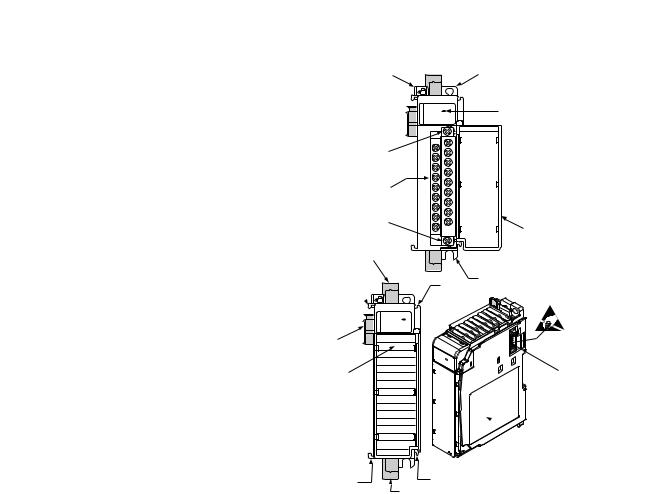
Hardware Features
1
10a
10
10b
8a
7a
OK
Analog
5a
9
2a
DANGER
Do Not Remove RTB Under Power
Unless Area is Non-Hazardous
|
|
V in 0 + |
|
|
||
V in 1+ |
|
|
|
|
|
|
|
|
V/I |
in 0- |
|
|
|
V/I in 1- |
|
|
||||
|
|
|
|
|
||
|
|
I |
in 0 + |
|
|
|
I in 1+ |
|
|
||||
|
|
V in 2+ |
|
|
||
V in 3+ |
|
|
|
|||
|
|
|
|
|
|
|
|
|
V/I |
in 2 - |
|
|
|
V/I in 3- |
|
|
|
|||
|
|
|
|
|
|
|
|
|
I |
in 2+ |
|
|
|
I in 3 + |
|
|
|
|||
|
|
ANLG |
|
|
||
ANLG |
|
Com |
|
|
||
Com |
V out 0+ |
|
|
|||
V out 1+ |
|
4 |
||||
|
|
|
|
|||
|
|
I out 0+ |
|
|||
I out 1+ |
|
|||||
|
|
|
|
|||
|
|
Ensure Adjacent |
||||
Bus Lever is Unlatched/Latched |
||||||
Before/After |
|
|
||||
Removing/Inserting Module |
|
|||||
1769-IF4FXOF2F |
|
|||||
OK |
|
2b |
|
|
3 |
Analog |
|
|
|
7a |
|
5b
 6
6
|
7b |
8b |
7b |
|
|
|
|
|
|
|
|
Item |
Description |
|
|
|
|
||
1 |
Bus lever (with locking function) |
||
|
|
|
|
2a |
Upper-panel mounting tab |
|
|
|
|
|
|
2b |
Lower-panel mounting tab |
|
|
|
|
|
|
3 |
Module status indicators |
|
|
|
|
||
4 |
Module door with terminal identification label |
||
|
|
||
5a |
Movable bus connector with female pins |
||
|
|
||
5b |
Stationary bus connector with male pins |
||
|
|
|
|
6 |
Nameplate label |
|
|
|
|
||
7a |
Upper tongue-and-groove slots |
||
|
|
||
7b |
Lower tongue-and-groove slots |
||
|
|
|
|
8a |
Upper DIN-rail latch |
|
|
|
|
|
|
8b |
Lower DIN-rail latch |
|
|
|
|
||
9 |
Write-on label for user identification tags |
||
|
|
||
10 |
Removable terminal block (RTB) with finger-safe cover |
||
|
|
|
|
10a |
RTB retaining screw |
|
|
|
|
|
|
10b |
RTB retaining screw |
|
|
|
|
|
|
10 |
Publication 1769-UM019A-EN-P - October 2008 |
Overview |
Chapter 1 |
|
|
System Overview
Module Operation
The module communicates to the controller through the bus interface. The module also receives 5 and 24V DC power through the bus interface.
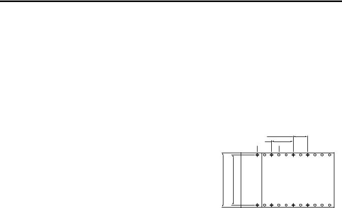
You can install as many analog modules as your power supply can support. However, the modules may not be located more than eight modules away from the system power supply.
Determine Power Supply Distance
CompactLogix Controller or I/O Communication Adapter |
Compact I/O |
Compact I/O |
Compact I/O |
System Power Supply |
Compact I/O |
Compact I/O |
Compact I/O |
End Cap |
|
|
|
|
|
|
|
|
|
|
Supply Distance |
4 |
3 |
2 |
1 |
|
1 |
2 |
3 Power |
||
or
MicroLogix 1500 Controller |
CompactI/O |
CompactI/O |
CompactI/O |
CompactI/O |
CapEnd |
|
|
|
|
|
|
|
|
with Integrated System |
|
|
|
|
|
|
Power Supply |
|
|
|
|
|
|
|
|
|
|
|
|
|
|
1 |
2 |
3 |
4 |
Power Supply Distance |
|
When you cycle power, the module performs a check of its internal circuits, memory, and basic functions. During this time, the module-status OK indicator remains off. If no faults are found during power-cycle diagnostics, the module-status OK indicator is turned on.
After power-cycle checks are complete, the module waits for valid channel-configuration data. If an invalid configuration is detected, the module generates a configuration error. Once a channel is properly configured and enabled, the module begins its conversion process.
Each time an input channel is read, the converted analog data value is tested for an over-range or under-range condition. In addition, the module supports user-configured high and low alarm condition tests for each input channel. If any of these conditions are detected, unique bits are set in the input-channel status word.
Publication 1769-UM019A-EN-P - October 2008 |
11 |

Chapter 1 |
Overview |
|
|
Each time a new output value is sent to the module, it is tested for an over-range or under-range condition. In addition, the module supports user-configured high and low output clamps for each output channel. If any of these conditions are detected, unique bits are set in the output-channel status word.
The channel status words are described in the Input Data File on page 36.
The controller uses two’s complement binary data when communicating with the module. This typically occurs at the end of the program scan or when commanded by the control program. If the controller and the module determine that the bus data transfer was made without error, the input data is used in your control program and the output data is used by the module.
No field calibration is required.
12 |
Publication 1769-UM019A-EN-P - October 2008 |

Chapter 2
Introduction
General Considerations
Installation and Wiring
Topic |
Page |
|
|
General Considerations |
13 |
|
|
Assemble the Compact I/O System |
16 |
|
|
Mounting the Module |
17 |
|
|
Replace a Single Module Within a System |
19 |
|
|
Grounding the Module |
20 |
|
|
System Wiring Guidelines |
21 |
|
|
Label the Terminals |
24 |
|
|
Remove the Finger-safe Terminal Block |
25 |
|
|
Wire the Finger-safe Terminal Block |
25 |
|
|
Wire the Modules |
27 |
|
|
The Compact I/O system is suitable for use in an industrial environment when installed in accordance with these instructions. Specifically, this equipment is intended for use in clean, dry
environments (Pollution degree 2(1)) and to circuits not exceeding Over Voltage Category II(2) (IEC 60664-1).(3)
(1)Pollution Degree 2 is an environment where, normally, only non-conductive pollution occurs except that occasionally a temporary conductivity caused by condensation shall be expected.
(2)Over Voltage Category II is the load level section of the electrical distribution system. At this level, transient voltages are controlled and do not exceed the impulse voltage capability of the product’s insulation.
(3)Pollution Degree 2 and Over Voltage Category II are International Electrotechnical Commission (IEC) designations.
Publication 1769-UM019A-EN-P - October 2008 |
13 |

Chapter 2 Installation and Wiring
Hazardous Location Considerations
This equipment is suitable for use in Class I, Division 2, Groups A, B, C, D or nonhazardous locations only. The following attention statement applies to use in hazardous locations.
ATTENTION |
EXPLOSION HAZARD |
|||
• Substitution of components may impair suitability for Class I, |
||||
|
|
|
||
|
|
|
||
|
|
|
Division 2. |
|
|
|
|
• Do not replace components or disconnect equipment unless |
|
|
|
|
||
|
|
|
||
|
|
|
power has been switched off or the area is known to be |
|
|
|
|
nonhazardous. |
|
|
|
|
• Do not connect or disconnect components unless power has |
|
|
|
|
been switched off or the area is known to be nonhazardous. |
|
|
|
|
• This product must be installed in an enclosure. |
|
|
|
|
• All wiring must comply with N.E.C. article 501-4(b). |
|
|
|
|
|
|
Prevent Electrostatic Discharge
ATTENTION |
Electrostatic discharge can damage integrated circuits or |
|||
semiconductors if you touch analog I/O module bus-connector pins |
||||
|
|
|
||
|
|
|
||
|
|
|
or the terminal block on the input module. Follow these guidelines |
|
|
|
|
when you handle the module: |
|
|
|
|
|
|
•Touch a grounded object to discharge static potential.
•Wear an approved wrist-strap grounding device.
•Do not touch the bus connector or connector pins.
•Do not touch circuit components inside the module.
•Use a static-safe work station, if available.
•Keep the module in its static-shield box, when it is not in use.
14 |
Publication 1769-UM019A-EN-P - October 2008 |

Installation and Wiring Chapter 2
Remove Power
ATTENTION |
Remove power before removing or inserting this module. When |
|||
you remove or insert a module with power applied, an electrical |
||||
|
|
|
||
|
|
|
||
|
|
|
arc may occur. An electrical arc can cause personal injury or |
|
|
|
|
property damage by: |
|
|
|
|
|
|
•sending an erroneous signal to your system’s field devices, causing unintended machine motion.
•causing an explosion in a hazardous environment.
Electrical arcing causes excessive wear to contacts on both the module and its mating connector and may lead to premature failure.
Reduce Noise
Most applications require installation in an industrial enclosure to reduce the effects of electrical interference. Analog inputs and outputs are highly susceptible to electrical noise. Electrical noise coupled to the analog inputs and outputs reduces the performance (accuracy) of the module.
Group your modules to minimize adverse effects from radiated electrical noise and heat. Consider the following conditions when selecting a location for the analog module. Position the module:
•away from sources of electrical noise such as hard-contact switches, relays, and AC motor drives.
•away from modules that generate significant radiated heat, such as the 1769-IA16 module. Refer to the module’s heat dissipation specification.
In addition, route shielded, twisted-pair analog input wiring away from any high-voltage I/O wiring.
Protecting the Circuit Board from Contamination
The printed circuit board of the module must be protected from dirt, oil, moisture, and other airborne contaminants. To protect the board, the system must be installed in an enclosure suitable for the environment. The interior of the enclosure should be kept clean and the enclosure door should be kept closed whenever possible.
Publication 1769-UM019A-EN-P - October 2008 |
15 |
Chapter 2 Installation and Wiring
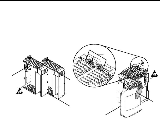
Assemble the Compact I/O
System
The module can be attached to the controller or an adjacent I/O module before or after mounting.
For mounting instructions, see Panel Mounting By Using the Dimensional Template on page 18, or Mount to a DIN Rail on page 19. To work with a system that is already mounted, see Replace a Single Module Within a System on page 19.
3
4
2
1
6
1
5
1.Disconnect power.
2.Check that the bus lever of the module to be installed is in the unlocked (fully right) position.
3.Use the upper and lower tongue-and-groove slots (1) to secure the modules together (or to a controller).
4.Move the module back along the tongue-and-groove slots until the bus connectors (2) line up with each other.
5.Use your fingers or a small screwdriver to push the bus lever back slightly to clear the positioning tab (3).
16 |
Publication 1769-UM019A-EN-P - October 2008 |
Installation and Wiring |
Chapter 2 |
|
|
Mounting the Module
6.To allow communication between the controller and module, move the bus lever fully to the left (4) until it clicks.
Make sure it is locked firmly in place.
ATTENTION |
When attaching I/O modules, it is very important that |
|||
the bus connectors are securely locked together to be |
||||
|
|
|
||
|
|
|
||
|
|
|
sure of proper electrical connection. |
|
|
|
|
|
|
|
|
|
|
|
|
|
|
|
|
7.Attach an end cap terminator (5) to the last module in the system by using the tongue-and-groove slots as before.
8.Lock the end cap bus terminator (6).
|
A 1769-ECR or 1769-ECL right or left end cap must be used to |
|
IMPORTANT |
||
terminate the end of the bus. |
||
|
||
|
||
|
|
Modules may be mounted to a panel or to a DIN rail.
ATTENTION |
During panel or DIN rail mounting of all devices, be sure that all |
|||
debris (that is, metal chips or wire strands) is kept from falling |
||||
|
|
|
||
|
|
|
||
|
|
|
into the module. Debris that falls into the module could cause |
|
|
|
|
damage when you cycle power. |
|
|
|
|
|
|
|
|
|
|
|
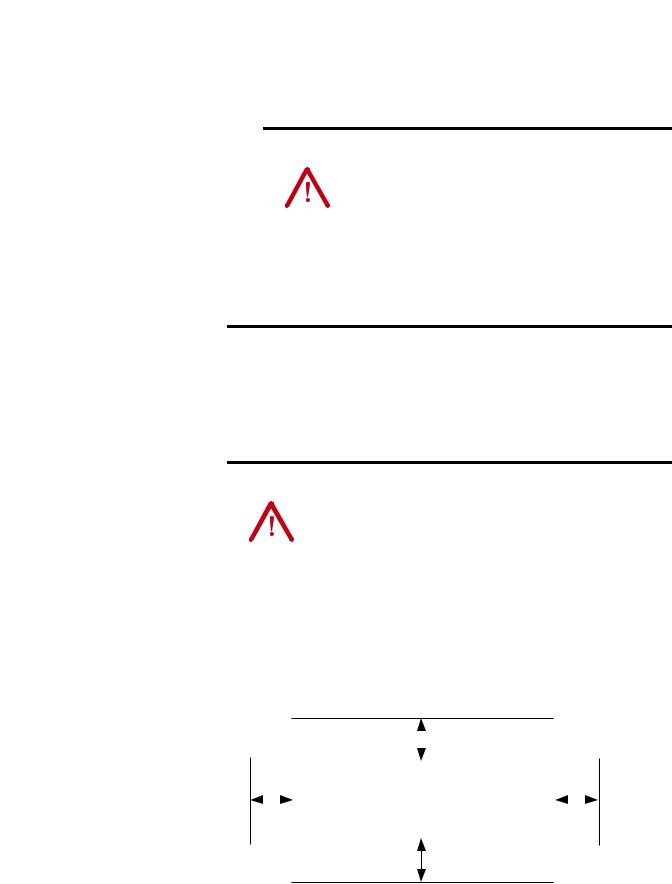
Minimum Spacing
Maintain spacing from enclosure walls, wireways, or adjacent equipment. Allow 50 mm (2 in.) of space on all sides for adequate ventilation.
Space Requirements
|
|
|
|
|
|
Top |
|
|
|
|
|
|
|
|
|
|
|
|
|
|
|
|
|
|
|
|
|
|
|
|
|
|
|
|
|
|
|
|
|
||
|
|
|
Host Controller |
I/OCompact |
|
I/OCompact |
I/OCompact |
I/OCompact |
I/OCompact |
CapEnd |
|
||
|
|
|
|
|
|
|
|
|
|
|
|
||
|
|
|
|
|
|
|
|
|
|
|
|
|
|
Side |
|
|
|
|
|
|
|
|
|
|
|
Side |
|
|
|
|
|
|
|
|
|
|
|
|
|
|
|
Bottom
Publication 1769-UM019A-EN-P - October 2008 |
17 |
Chapter 2 Installation and Wiring
Mount to a Panel
Mount the module to a panel by using two screws per module. Use M4 or #8 panhead screws. Mounting screws are required on every module.
Panel Mounting By Using the Dimensional Template
Locate holes every 17.5 mm (0.689 in.) to allow for a mix of single-wide and one-and-a-half-wide modules (for example, the 1769-OA16 module).
Spacing for single-wide modules 35 mm (1.378 in.).
Spacing for one-and-a-halfMounting-wide modules 52.5 mm (2.067 in.).
Refer to host controller documentation for this dimension.


Overall hole spacing tolerance: ±0.4 mm (0.016 in.).
Host Controller
Panel Mounting By Using the Modules as a Template
This procedure lets you use the assembled modules as a template for drilling holes in the panel. If you have sophisticated panel-mounting equipment, you can use the dimensional template provided. Due to module mounting-hole tolerance, it is important to follow these procedures.
1.On a clean work surface, assemble no more than three modules.
2.Using the assembled modules as a template, carefully mark the center of all module-mounting holes on the panel.
3.Return the assembled modules to the clean work surface, including any previously mounted modules.
4.Drill and tap the mounting holes for the recommended M4 or #8 screw.
5.Place the modules back on the panel, and check for proper hole alignment.
18 |
Publication 1769-UM019A-EN-P - October 2008 |
Installation and Wiring |
Chapter 2 |
|
|
Replace a Single Module
Within a System
6. Attach the modules to the panel by using the mounting screws.
TIP |
If mounting more modules, mount only the last one of this group |
|
and put the others aside. This reduces remounting time during |
||
|
||
|
||
|
drilling and tapping of the next group. |
7. Repeat steps 1…6 for any remaining modules.
Mount to a DIN Rail
The module can be mounted by using the following DIN rails:
•35 x 7.5 mm (EN 50 022 - 35 x 7.5)
•35 x 15 mm (EN 50 022 - 35 x 15).
Before mounting the module on a DIN rail, close the DIN rail latches. Press the DIN-rail mounting area of the module against the DIN rail. The latches will momentarily open and lock into place.
The module can be replaced while the system is mounted to a panel (or DIN rail). Follow these steps in order.
1. Remove power.
ATTENTION |
Remove power before removing or inserting this module. When |
|||
you remove or insert a module with power applied, an electrical |
||||
|
|
|
||
|
|
|
||
|
|
|
arc may occur. An electrical arc can cause personal injury or |
|
|
|
|
property damage by: |
|
|
|
|
|
|
•sending an erroneous signal to your system’s field devices, causing unintended machine motion.
•causing an explosion in a hazardous environment.
Electrical arcing causes excessive wear to contacts on both the module and its mating connector and may lead to premature failure.
2.On the module to be removed, remove the upper and lower mounting screws from the module or open the DIN latches by using a flat-blade or Phillips screwdriver.
3.Move the bus lever to the right to disconnect (unlock) the bus.
Publication 1769-UM019A-EN-P - October 2008 |
19 |

Chapter 2 Installation and Wiring
Grounding the Module
4.On the right-side adjacent module, move its bus lever to the right (unlock) to disconnect it from the module to be removed.
5.Gently slide the disconnected module forward.
If you feel excessive resistance, check that the module has been disconnected from the bus, and that both mounting screws have been removed or DIN latches opened.
TIP |
It may be necessary to rock the module slightly |
|
from front to back to remove it, or, in a |
||
|
||
|
||
|
panel-mounted system, to loosen the screws of |
|
|
adjacent modules. |
6.Before installing the replacement module, be sure that the bus lever on the module to be installed and on the right-side adjacent module are in the unlocked (fully right) position.
7.Slide the replacement module into the open slot.
8.Connect the modules together by locking (fully left) the bus levers on the replacement module and the right-side adjacent module.
9.Replace the mounting screws or snap the module onto the DIN rail.
This product is intended to be mounted to a well-grounded mounting surface, such as a metal panel. Additional grounding connections from the module’s mounting tabs or DIN rail (if used) are not required unless the mounting surface cannot be grounded. Refer to Industrial Automation Wiring and Grounding Guidelines, publication 1770-4.1, for additional information.
20 |
Publication 1769-UM019A-EN-P - October 2008 |
Installation and Wiring |
Chapter 2 |
|
|
System Wiring Guidelines |
Consider the following when wiring your system: |
•All module commons (ANLG Com) are connected in the analog module.
•The analog common (ANLG Com) is not connected to earth ground inside the module.
•Channels are not isolated from each other.
•For optimum accuracy, limit overall cable impedance by keeping your cable as short as possible. Locate the I/O system as close to your sensors or actuators as your application will permit.
•Use Belden 8761, or equivalent, shielded wire.
•Under normal conditions, the drain wire and shield junction must be connected to earth ground via a panel or DIN rail mounting screw at the analog I/O module end.(1) Keep shield connection to ground as short as possible.
•If multiple power supplies are used with analog inputs, the power supply commons must be connected.
•The module does not provide loop power for analog inputs. Use a Class 2 power supply that matches the input transmitter specifications.
•Differential analog inputs are more immune to noise than single-ended analog inputs.
•Voltage outputs (Vout 0+ and Vout 1+) of the 1769-IF4FXOF2F
module are referenced to ANLG Com. Load resistance for a voltage output channel must be equal to or greater than 1 kΩ .
•Current outputs (Iout 0+ and Iout 1+) of the 1769-IF4FXOF2F module source current that returns to ANLG Com. Load
resistance for a current output channel must remain between 0 and 500 Ω .
•Voltages on Vin+, V/Iin-, and Iin+ terminals of the 1769-IF4FXOF2F module must be within ±10V DC of analog common (ANLG Com).
(1)In environments where high-frequency noise may be present, it may be necessary to directly ground cable shields to earth at the module end and via a 0.1 µF capacitor at the sensor end.
Publication 1769-UM019A-EN-P - October 2008 |
21 |

Chapter 2 Installation and Wiring
Effect of Transducer/Sensor and Cable Length Impedance on
Voltage Input and Output Accuracy
For voltage inputs and outputs, the length of the cable used between the transducer/sensor/load and the module can affect the accuracy of the data provided by the module.
Voltage Input Accuracy
|
|
Rs |
|
Rc |
||||||
+ |
|
|
|
|
|
|
|
|
|
Ri |
|
|
|
|
|
|
|
|
|
||
|
|
|
|
|
|
|
|
|
||
Vs |
|
|
|
|
V in |
|
|
|||
|
|
|
|
|
|
|
||||
|
|
|
|
|
|
|
||||
- |
|
|
|
|
|
|
|
|
|
|
|
|
|
|
|
|
|
|
|
|
|
|
|
|
|
|
Rc |
|||||
Where:
Rc = DC resistance of the cable (each conductor) depending on cable length
Rs = Source impedance of analog transducer/sensor input
Ri = Impedance of the voltage input (220 kΩ)
Vs = Voltage source (voltage at the transducer/sensor input device)
Vin = Measured potential at the module input
%Ai = Percent added inaccuracy in a voltage-based system due to source and cable impedance
[ Ri × V s]
Vin = -------------------------------------------------------
[Rs + ( 2 × Rc ) + Ri ]
For example, for Belden 8761 two conductor, shielded cable:
|
Rc = 5.25 Ω/1000 m |
|
|
V in |
||
|
Rs = 0 (ideal source) |
%Ai = |
1 – |
-------- |
||
|
V s × 100 |
|||||
Effect of Cable Length on Input Accuracy |
|
|
|
|
||
|
|
|
|
|
||
|
Length of Cable, |
DC Resistance of the Cable, |
|
Accuracy Impact at the |
||
|
m (ft) |
Rc (Ω) |
|
|
Input Module |
|
|
50 (164) |
2.625 |
|
|
0.002385% |
|
|
|
|
|
|
||
|
100 (328) |
5.25 |
|
|
0.00477% |
|
|
|
|
|
|
||
|
200 (656) |
10.50 |
|
|
0.00954% |
|
|
|
|
|
|
||
|
300 (984) |
15.75 |
|
|
0.01431% |
|
|
|
|
|
|
|
|
22 |
Publication 1769-UM019A-EN-P - October 2008 |

Installation and Wiring |
Chapter 2 |
|
|
As input source impedance (Rs) and/or resistance (DC) of the cable (Rc) get larger, system accuracy decreases. If you determine that the inaccuracy error is significant, implementing the following equation in the control program can compensate for the added inaccuracy error due to the impedance of the source and cable.
|
V s = V in × |
[ Rs + ( 2 × Rc ) + Ri] |
|
|
------------------------------------------------------- |
||
|
|
Ri |
|
|
For current signals, source and cable impedance do not impact |
||
TIP |
|||
system accuracy. |
|
||
|
|
||
|
|
||
Voltage Output Accuracy
|
|
|
Rs |
|
|
|
Rc |
|
|
|||||
+ |
|
|
|
|
|
|
|
|
|
|
|
|
|
Ri |
|
|
|
|
|
|
|
|
|
|
|
|
|
||
Vs |
|
|
|
|
|
|
|
|
V in |
|
|
|||
|
|
|
|
|
|
|
|
|
|
|
||||
- |
|
|
|
|
|
|
|
|
|
|
|
|
|
|
|
|
|
|
|
|
|
|
|
|
|
|
|
|
|
|
|
|
|
|
|
|
|
|
Rc |
|
|
|||
Where:
Rc = DC resistance of the cable (each conductor) depending on cable length
Rs = Source impedance (1 Ω)
Ri = Impedance of the voltage input
Vs = Voltage at the output of 1769-IF4FXOF2F module
Vin = Measured potential at the module input
%Ai = Percent added inaccuracy in a voltage-based system due to source and cable impedance
[ Ri × V s]
Vin = -------------------------------------------------------
[Rs + ( 2 × Rc ) + Ri ]
Publication 1769-UM019A-EN-P - October 2008 |
23 |

Chapter 2 Installation and Wiring
Label the Terminals
For example, for Belden 8761 two conductor, shielded cable and a 1769-IF4 input module:
Rc = 52.5 Ω/1000 m |
|
V in |
||
Rs = 1 Ω |
%Ai = |
1 – |
-------- |
|
V s × 100 |
||||
Ri = 220 KΩ |
|
|
|
|
Effect of Output Impedance and Cable Length on Accuracy |
||||
|
|
|
|
|
Length of Cable |
DC Resistance of the Cable Rc |
|
Accuracy Impact at the |
|
|
|
|
Input Module |
|
|
|
|
|
|
50 m (164 ft) |
2.625 Ω |
|
0.00284% |
|
|
|
|
|
|
100 m (328 ft) |
5.25 Ω |
|
0.00523% |
|
|
|
|
|
|
200 m (656 ft) |
10.50 Ω |
|
0.01% |
|
|
|
|
|
|
300 m (984 ft) |
15.75 Ω |
|
0.01477% |
|
|
|
|
|
|
As output impedance (Rs) and/or resistance (DC) of the cable (Rc) get larger, system accuracy decreases. If you determine that the inaccuracy error is significant, implementing the following equation in the control program can compensate for the added inaccuracy error due to the impedance of the module’s voltage outputs and cable.
TIP |
For current outputs, source and cable impedance do not impact |
|
system accuracy as long as the total resistance of the cable and |
||
|
||
|
||
|
input impedance of the load remain within the specified |
|
|
maximum limits for the module's current outputs. |
× [ Rs + ( 2 × Rc ) + Ri]
V s = V in -------------------------------------------------------
Ri
A removable, write-on label is provided with the module. Remove the label from the door, mark the identification of each terminal with permanent ink, and slide the label back into the door. Your markings (ID tag) will be visible when the module door is closed.
24 |
Publication 1769-UM019A-EN-P - October 2008 |

Installation and Wiring |
Chapter 2 |
|
|
Remove the Finger-safe
Terminal Block
Wire the Finger-safe
Terminal Block
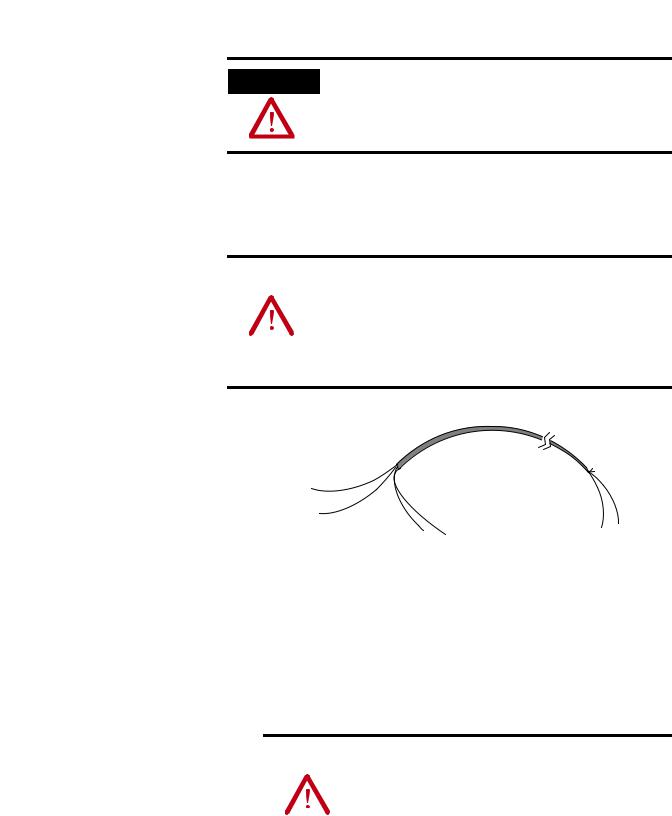
When wiring field devices to the module, it is not necessary to remove the terminal block. If you remove the terminal block, use the write-on label on the side of the terminal block to identify the module slot location and type. RTB position (for one-and-a-half size modules) can be indicated by circling either the R for right side or L for left side.
Finger-safe Terminal Block
 R SLOT # ____ L
MODULE TYPE _____ RoHS
To remove the terminal block, loosen the upper and lower retaining screws. The terminal block will back away from the module as you remove the screws. When replacing the terminal block, torque the retaining screws to 0.46 N•m (4.1 lb•in).
Upper Retaining Screw
Lower Retaining Screw
When wiring the terminal block, keep the finger-safe cover in place.
1.Loosen the terminal screws to be wired.
2.Begin wiring at the bottom of the terminal block and move up.
Publication 1769-UM019A-EN-P - October 2008 |
25 |

Chapter 2 Installation and Wiring
3.Route the wire under the terminal pressure plate.
You can use the bare wire or a spade lug. The terminals accept a 6.35 mm (0.25 in.) spade lug.
TIP |
The terminal screws are non-captive. Therefore, it is possible to |
|
use a ring lug (maximum 1/4 in. o.d. with a 0.139 in. minimum |
||
|
||
|
||
|
i.d. (M3.5)) with the module. |
4.Tighten the terminal screw making sure the pressure plate secures the wire.
Recommended torque when tightening terminal screws is 0.68 N•m (6 lb•in).
TIP |
If you need to remove the finger-safe cover, insert a screwdriver |
|
into one of the square, wiring holes and gently pry the cover off. |
||
|
||
|
||
|
If you wire the terminal block with the finger-safe cover |
|
|
removed, you will not be able to put it back on the terminal |
|
|
block because the wires will be in the way. |
Wire Size and Terminal Screw Torque
Each terminal accepts up to two wires.
|
Wire Type |
Wire Size |
Terminal Screw Torque |
Retaining Screw Torque |
||
|
|
|
|
|
|
|
Solid |
|
Cu-90 °C (194 °F) |
0.325…2.080 mm2 (22…14 AWG) |
0.68 |
N•m (6 lb•in) |
0.46 N•m (4.1 lb•in) |
Stranded |
|
Cu-90 °C (194 °F) |
0.325…1.310 mm2 (22…16 AWG) |
0.68 |
N•m (6 lb•in) |
0.46 N•m (4.1 lb•in) |
26 |
Publication 1769-UM019A-EN-P - October 2008 |
Installation and Wiring |
Chapter 2 |
|
|
Wire the Modules
ATTENTION
To prevent shock hazard, care should be taken when wiring the module to analog signal sources. Before wiring any analog module, disconnect power from the system power supply and from any other source to the analog module.
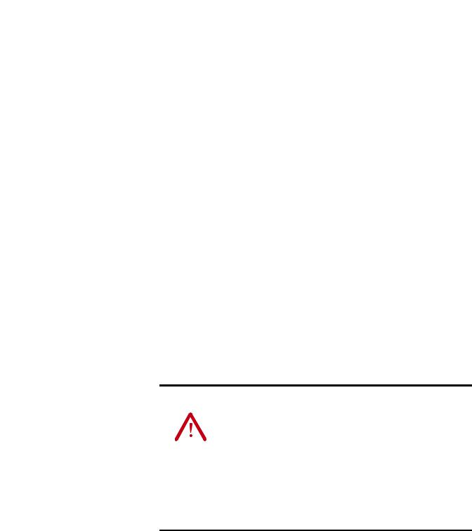
After the analog module is properly installed, follow the wiring procedure below. For proper operation and high immunity to electrical noise, always use Belden 8761 (shielded, twisted-pair) or equivalent wire.
ATTENTION |
When wiring an analog input, take care to avoid connecting a |
|||
voltage source to a channel configured for current input. |
||||
|
|
|
||
|
|
|
||
|
|
|
Improper module operation or damage to the voltage source |
|
|
|
|
can occur. |
|
|
|
|
|
|
Never connect a voltage or current source to an analog output channel.
Belden 8761 Wire
Cable |
Cut foil shield |
|
and drain wire. |
Signal Wire
Signal Wire
Drain Wire |
Foil Shield |
Signal Wire |
Signal Wire |
|
|
|
To wire your module, follow these steps.
1.At each end of the cable, strip some casing to expose the individual wires.
2.Trim the signal wires to 2-in. lengths.
3.Strip about 5 mm (3/16 in.) of insulation away to expose the end of the wire.
ATTENTION |
Be careful when stripping wires. Wire fragments that |
|||
fall into a module could cause damage when you cycle |
||||
|
|
|
||
|
|
|
||
|
|
|
power. |
|
|
|
|
|
|
|
|
|
|
|
|
|
|
|
|
Publication 1769-UM019A-EN-P - October 2008 |
27 |
Chapter 2 Installation and Wiring
4.At one end of the cable, twist the drain wire and foil shield together.
Under normal conditions, this drain wire and shield junction must be connected to earth ground, via a panel or DIN rail mounting screw at the analog I/O module end. Keep the length of the drain wire as short as possible.
In environments where high frequency noise may be present, it may be necessary to also ground the cable shields to earth via a 0.1 µF capacitor at the sensor end.
5.At the other end of the cable, cut the drain wire and foil shield back to the cable, unless the sensor end of the cable requires the shields to be connected to earth ground via the capacitor described in step 4.
6.Connect the signal wires to the terminal block.
7.Connect the other end of the cable to the analog input or output device.
8.Repeat steps 1…6 for each channel on the module.
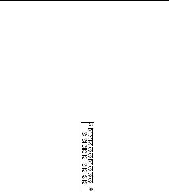
Terminal Layout
V in 1+ |
V in 0+ |
|
V/I in 0- |
||
V/I in 1 - |
||
|
||
I in 1+ |
I in 0+ |
|
|
||
V in 3+ |
V in 2 + |
|
V/I in 2- |
||
V/I in 3 - |
||
I in 2+ |
||
I in 3+ |
||
ANLG Com |
||
ANLG Com |
||
V out 0+ |
||
V out 1+ |
||
I out 0+ |
||
I out 1+ |
||
|
28 |
Publication 1769-UM019A-EN-P - October 2008 |
Installation and Wiring |
Chapter 2 |
|
|
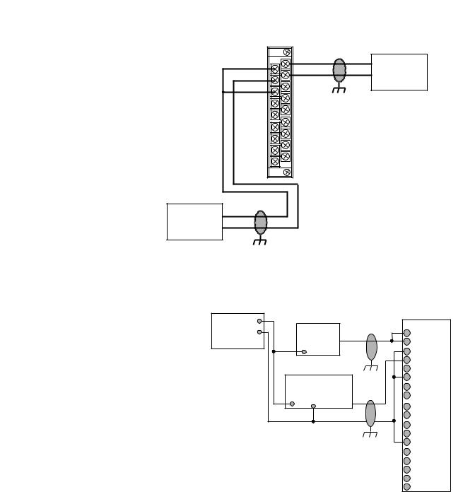
Wire Differential Inputs
V in 1+
V/I in 1 -
I in 1+
V in 3+
V/I in 3 -
I in 3+
ANLG Com
V out 1+
I out 1+
Belden 8761 Cable (or equivalent)
V in 0+ |
+ Differential |
V/I in 0- |
Voltage |
I in 0+ |
– Transmitter (1) |
V in 2 + |
Earth Ground the |
V/I in 2- |
Shield Locally at |
I in 2+ |
the Module |
ANLG Com |
|
V out 0+ |
|
I out 0+ |
|
Differential
Current
Transmitter (1)
+ |
– |
(1) The sensor power supply must be rated Class 2.
Earth Ground the Shield
Locally at the Module
Wiring Single-ended Sensor/Transmitter Types
Sensor/ |
+ |
|
|
|
Terminal Block |
Current |
|
|
|||
Transmitter |
- |
|
V in 0+ |
||
Power Supply(1) |
Transmitter |
I in 0+ |
|||
|
|
+ |
Signal |
V/I in 0 - |
|
|
|
|
|||
|
|
|
|
|
V in 1+ |
|
|
|
|
|
I in 1+ |
|
Voltage |
|
|
V/I in 1- |
|
|
|
|
V in 2+ |
||
|
Transmitter |
|
|||
|
|
I in 2+ |
|||
|
+ |
Ground |
Signal |
||
|
V/I in 2- |
||||
|
|
|
|
|
|
|
|
|
|
|
V in 3+ |
|
|
|
|
|
I in 3+ |
|
|
|
|
|
V/I in 3- |
|
|
|
|
|
ANLG Com |
|
|
|
|
|
ANLG Com |
|
|
|
|
|
V out 0+ |
|
|
|
|
|
I out 0+ |
|
|
|
|
|
V out 1+ |
|
|
|
|
|
I out 1 + |
(1) The sensor power supply must be rated Class 2.
Publication 1769-UM019A-EN-P - October 2008 |
29 |
Loading...