Rockwell Automation 1769-IF4 User Manual

Installation Instructions
Compact™ 1769-IF4 (Series B or Later) Analog Input Module
Inside |
|
Module Description .................................................................................. |
2 |
Module Installation................................................................................... |
3 |
System Assembly...................................................................................... |
4 |
Mounting Expansion I/O ........................................................................... |
6 |
Replacing a Single Module within a System ........................................... |
8 |
Module Spare/Replacement Parts ........................................................... |
8 |
Field Wiring Connections.......................................................................... |
9 |
I/O Memory Mapping ............................................................................. |
15 |
Specifications ......................................................................................... |
17 |
Hazardous Location Considerations ....................................................... |
20 |
Environnements dangereux .................................................................... |
20 |
For More Information .............................................................................. |
21 |
Publication 1769-IN048A-EN-P

2 Compact™ 1769-IF4 (Series B or Later) Analog Input Module
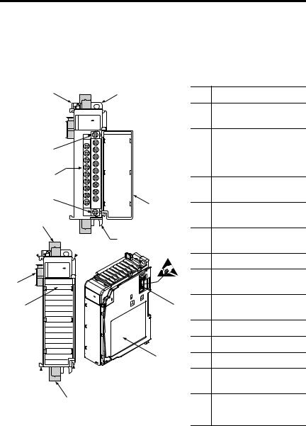
Module Description
1
10a
10
10b
8a
7a
OK
Analog
5a
9
7b
2a
OK  3
3
Analog
DANGER
Do Not Remove RTB Under Power
Unless Area is Non-Hazardous
|
|
V in 0 + |
||
V/I in 0 - |
|
|
|
|
|
|
I |
in 0+ |
|
ANLG |
||||
|
|
|||
Com |
V in 1 + |
|||
V/I in 1 - |
||||
|
|
I |
in 1+ |
|
ANLG |
||||
|
|
|||
Com |
V in 2 + |
|||
V/I in 2 - |
||||
|
|
|||
|
|
I |
in 2+ |
|
ANGL |
||||
Com |
|
V in 3 + |
||
V/I in 3 - |
||||
|
|
|||
|
|
I |
in 3+ |
|
ANGL |
||||
|
|
|
||
Com |
|
+24V dc |
||
dc |
||||
|
|
|||
NEUT |
Ensure Adjacent |
|||
Bus Lever is Unlatched/Latched
Before/After
Removing/Inserting Module
1769-IF4
2b
 7a
7a
 7b
7b
8b
Item Description
1bus lever
(with locking function)
2a |
upper panel mounting tab |
|
|
2b |
lower panel mounting tab |
|
|
3 |
module status LED |
4module door with terminal identification label
4 |
|
5a |
movable bus connector |
|
|
||
|
|
|
with female pins |
|
|
5b |
stationary bus connector |
|
|
|
with male pins |
|
|
6 |
nameplate label |
|
|
7a |
upper |
|
|
|
tongue-and-groove slots |
|
5b |
7b |
lower |
|
|
tongue-and-groove slots |
|
|
|
|
|
|
|
8a |
upper DIN rail latch |
|
|
8b |
lower DIN rail latch |
6 |
|
9 |
write-on label (user ID tag) |
10removable terminal block (RTB) with finger-safe cover
10a |
RTB upper retaining screw |
|
|
10b |
RTB lower retaining screw |
Publication 1769-IN048A-EN-P

Compact™ 1769-IF4 (Series B or Later) Analog Input Module |
3 |
|
|
Module Installation
Compact I/O is suitable for use in an industrial environment when installed in accordance with these instructions. Specifically, this equipment is
intended for use in clean, dry environments (Pollution degree 2(1)) and to circuits not exceeding Over Voltage Category II(2) (IEC 60664-1).(3)
Prevent Electrostatic Discharge
ATTENTION |
Electrostatic discharge can damage integrated circuits or |
|
semiconductors if you touch bus connector pins or the |
||
|
||
|
terminal block. Follow these guidelines when you handle |
!the module:
•Touch a grounded object to discharge static potential.
•Wear an approved wrist-strap grounding device.
•Do not touch the bus connector or connector pins.
•Do not touch circuit components inside the module.
•If available, use a static-safe work station.
•When not in use, keep the module in its static-shield box.
(1)Pollution Degree 2 is an environment where, normally, only non-conductive pollution occurs except that occasionally a temporary conductivity caused by condensation shall be expected.
(2)Over Voltage Category II is the load level section of the electrical distribution system. At this level transient voltages are controlled and do not exceed the impulse voltage capability of the product’s insulation.
(3)Pollution Degree 2 and Over Voltage Category II are International Electrotechnical Commission (IEC) designations.
Publication 1769-IN048A-EN-P

4 Compact™ 1769-IF4 (Series B or Later) Analog Input Module
Remove Power
ATTENTION |
Remove power before removing or inserting this module. |
|
When you remove or insert a module with power |
||
|
||
|
applied, an electrical arc may occur. An electrical arc can |
!cause personal injury or property damage by:
•sending an erroneous signal to your system’s field devices, causing unintended machine motion
•causing an explosion in a hazardous environment
Electrical arcing causes excessive wear to contacts on both the module and its mating connector. Worn contacts may create electrical resistance.
System Assembly
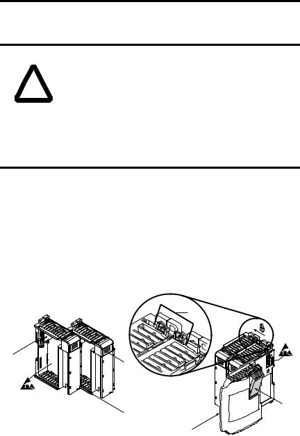
The module can be attached to the controller or an adjacent I/O module before or after mounting. For mounting instructions, see “Panel Mounting” on page 6, or “DIN Rail Mounting” on page 7. To work with a system that is already mounted, see “Replacing a Single Module within a System” on page 8.
The following procedure shows you how to assemble the Compact I/O system.
3
4
2
1
6
1
5
Publication 1769-IN048A-EN-P

Compact™ 1769-IF4 (Series B or Later) Analog Input Module |
5 |
|
|
1.Disconnect power.
2.Check that the bus lever of the module to be installed is in the unlocked (fully right) position.
3.Use the upper and lower tongue-and-groove slots (1) to secure the modules together (or to a controller).
4.Move the module back along the tongue-and-groove slots until the bus connectors (2) line up with each other.
5.Push the bus lever back slightly to clear the positioning tab (3). Use your fingers or a small screwdriver.
6.To allow communication between the controller and module, move the bus lever fully to the left (4) until it clicks. Ensure it is locked firmly in place.
ATTENTION
When attaching I/O modules, it is very important that the bus connectors are securely locked together to ensure
!proper electrical connection.
7.Attach an end cap terminator (5) to the last module in the system by using the tongue-and-groove slots as before.
8.Lock the end cap bus terminator (6).
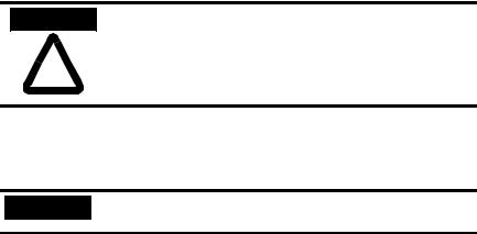
IMPORTANT |
A 1769-ECR or 1769-ECL right or left end cap must be |
|
used to terminate the end of the communication bus. |
||
|
Publication 1769-IN048A-EN-P

6 Compact™ 1769-IF4 (Series B or Later) Analog Input Module
Mounting Expansion I/O
ATTENTION
!
During panel or DIN rail mounting of all devices, be sure that all debris (metal chips, wire strands, etc.) is kept from falling into the module. Debris that falls into the module could cause damage on power up.
Minimum Spacing
Maintain spacing from |
|
|
|
|
|
enclosure walls, |
|
|
|
|
|
|
|
|
|
||
wireways, adjacent |
|
|
|
Host Controller |
|
equipment, etc. Allow |
|
|
|
||
Side |
|||||
50 mm (2 in.) of space |
|
||||
on all sides for |
|
|
|
|
|
adequate ventilation, as |
|
|
|
|
|
shown: |
|
|
|
|
|
Top
Compact I/O |
|
Compact I/O |
|
Compact I/O |
Compact I/O |
Compact I/O |
End Cap |
|
|
|
|
|
|
|
|
|
|
|
|
Bottom |
|
|
|
|
||
|
|
|
|
|
|
|||
|
|
|
|
|
|
|
|
|
Side
Panel Mounting
Mount the module to a panel using two screws per module. Use M4 or #8 panhead screws. Mounting screws are required on every module.
Panel Mounting Using the Dimensional Template
For more than 2 modules: (number of modules-1) X 35mm (1.38 in.) |
|
|
|
|
28.5 |
|||||
|
|
|
|
|||||||
Refer to host controller documentation for this dimension. |
|
35 |
|
|
|
|
||||
|
|
|
|
|
(1.38) |
|
|
|
(1.12) |
|
|
|
|
|
|
|
|
|
|
|
|
|
132 (5.197) |
|
||
NOTE: All dimensions are in mm (inches). |
|
|
|
|
|
|
122.6±0.2 |
||
|
|
(4.826±0.008) |
||
Hole spacing tolerance: ±0.4 mm (0.016 in.) |
|
|
||
|
|
|
|
|
|
|
|
|
|
|
|
|
|
|
Host Controller |
Compact I/O |
Compact I/O |
Compact I/O |
End Cap |
Publication 1769-IN048A-EN-P
Compact™ 1769-IF4 (Series B or Later) Analog Input Module |
7 |
|
|
Panel Mounting Procedure Using Modules as a Template
The following procedure allows you to use the assembled modules as a template for drilling holes in the panel. If you have sophisticated panel mounting equipment, you can use the dimensional template provided on page 6. Due to module mounting hole tolerance, it is important to follow these procedures:
1.On a clean work surface, assemble no more than three modules.
2.Using the assembled modules as a template, carefully mark the center of all module-mounting holes on the panel.
3.Return the assembled modules to the clean work surface, including any previously mounted modules.
4.Drill and tap the mounting holes for the recommended M4 or #8 screw.
5.Place the modules back on the panel and check for proper hole alignment.
6.Attach the modules to the panel using the mounting screws.
NOTE |
If mounting more modules, mount only the last one of |
|
this group and put the others aside. This reduces |
|
|
|
remounting time during drilling and tapping of the next |
|
group. |
7. Repeat steps 1 to 6 for any remaining modules.
DIN Rail Mounting
The module can be mounted using the following DIN rails: 35 x 7.5 mm (EN 50 022 - 35 x 7.5) or 35 x 15 mm (EN 50 022 - 35 x 15).
Before mounting the module on a DIN rail, close the DIN rail latches. Press the DIN rail mounting area of the module against the DIN rail. The latches will momentarily open and lock into place.
Publication 1769-IN048A-EN-P

8 Compact™ 1769-IF4 (Series B or Later) Analog Input Module
Replacing a Single Module within a System
The module can be replaced while the system is mounted to a panel (or DIN rail). Follow these steps in order:
1.Remove power. See important note on page 4.
2.On the module to be removed, remove the upper and lower mounting screws from the module (or open the DIN latches using a flat-blade or phillips-style screwdriver).
3.Move the bus lever to the right to disconnect (unlock) the bus.
4.On the right-side adjacent module, move its bus lever to the right (unlock) to disconnect it from the module to be removed.
5.Gently slide the disconnected module forward. If you feel excessive resistance, check that the module has been disconnected from the bus and that both mounting screws have been removed (or DIN latches opened).
NOTE |
It may be necessary to rock the module slightly from front |
|
to back to remove it, or, in a panel-mounted system, to |
|
|
|
loosen the screws of adjacent modules. |
6.Before installing the replacement module, be sure that the bus lever on the module to be installed, and on the right-side adjacent module are in the unlocked (fully right) position.
7.Slide the replacement module into the open slot.
8.Connect the modules together by locking (fully left) the bus levers on the replacement module and the right-side adjacent module.
9.Replace the mounting screws (or snap the module onto the DIN rail).
Module Spare/Replacement Parts
•Terminal block, catalog number 1769-RTBN18 (1 per kit)
•Door Labels, catalog number 1769-RL2 Series B (2 per kit)
•Door, catalog number 1769-RD (2 per kit)
Publication 1769-IN048A-EN-P
 Loading...