


 Loading...
Installation Instructions
1768 CompactLogix Power Supplies
Catalog Numbers 1768-PA3, 1768-PB3
Topic |
Page |
|
|
Important User Information |
2 |
|
|
About the 1768 Power Supplies |
5 |
|
|
Safety Circuits |
11 |
|
|
Main Power Disconnect |
12 |
|
|
Install the Power Supply |
16 |
|
|
Mount the Power Supply |
16 |
|
|
Place 1769 I/O Modules in a 1768 CompactLogix System |
22 |
|
|
Interpret the LED Indicators |
23 |
|
|
Specifications |
27 |
|
|
Additional Resources |
31 |
|
|
About This Publication
Use this publication to install the 1768-PA3 and 1768-PB3 CompactLogix power supplies.
Publication 1768-IN001B-EN-P - July 2006

2 1768 CompactLogix Power Supplies
Important User Information
Solid state equipment has operational characteristics differing from those of electromechanical equipment. Safety Guidelines for the Application, Installation and Maintenance of Solid State Controls (publication SGI-1.1 available from your local Rockwell Automation sales office or online at http://literature.rockwellautomation.com) describes some important differences between solid state equipment and hard-wired electromechanical devices. Because of this difference, and also because of the wide variety of uses for solid state equipment, all persons responsible for applying this equipment must satisfy themselves that each intended application of this equipment is acceptable.
In no event will Rockwell Automation, Inc. be responsible or liable for indirect or consequential damages resulting from the use or application of this equipment.
The examples and diagrams in this manual are included solely for illustrative purposes. Because of the many variables and requirements associated with any particular installation, Rockwell Automation, Inc. cannot assume responsibility or liability for actual use based on the examples and diagrams.
No patent liability is assumed by Rockwell Automation, Inc. with respect to use of information, circuits, equipment, or software described in this manual.
Reproduction of the contents of this manual, in whole or in part, without written permission of Rockwell Automation, Inc., is prohibited.
Throughout this manual, when necessary, we use notes to make you aware of safety considerations.
WARNING |
Identifies information about practices or circumstances that can cause an explosion in |
|
a hazardous environment, which may lead to personal injury or death, property |
||
|
||
|
damage, or economic loss. |
|
IMPORTANT |
Identifies information that is critical for successful application and understanding of |
|
the product. |
||
|
ATTENTION
Identifies information about practices or circumstances that can lead to personal injury or death, property damage, or economic loss. Attentions help you to identify a hazard, avoid a hazard, and recognize the consequences.
SHOCK HAZARD |
Labels may be located on or inside the equipment, for example, a drive or motor, to |
|
alert people that dangerous voltage may be present. |
||
|
BURN HAZARD |
Labels may be located on or inside the equipment, for example, a drive or motor, to |
|
alert people that surfaces may be dangerous temperatures. |
||
|
Publication 1768-IN001B-EN-P - July 2006

1768 CompactLogix Power Supplies 3
North American Hazardous Location Approval
The following Information applies when operating this |
|
Informations sur l'utilisation de cet équipement en |
|||||||||||
equipment in hazardous locations: |
|
environnements dangereux: |
|||||||||||
|
|
|
|
|
|
|
|
||||||
Products marked "CL I, DIV 2, GP A, B, C, D" are suitable for |
|
Les produits marqués "CL I, DIV 2, GP A, B, C, D" ne |
|||||||||||
use in Class I Division 2 Groups A, B, C, D, Hazardous |
|
conviennent qu'à une utilisation en environnements de |
|||||||||||
Locations and nonhazardous locations only. Each product is |
|
Classe I Division 2 Groupes A, B, C, D dangereux et non |
|||||||||||
supplied with markings on the rating nameplate indicating |
|
dangereux. Chaque produit est livré avec des marquages sur |
|||||||||||
the hazardous location temperature code. When combining |
|
sa plaque d'identification qui indiquent le code de |
|||||||||||
products within a system, the most adverse temperature code |
|
température pour les environnements dangereux. Lorsque |
|||||||||||
(lowest "T" number) may be used to help determine the |
|
plusieurs produits sont combinés dans un système, le code |
|||||||||||
overall temperature code of the system. Combinations of |
|
de température le plus défavorable (code de température le |
|||||||||||
equipment in your system are subject to investigation by the |
|
plus faible) peut être utilisé pour déterminer le code de |
|||||||||||
local Authority Having Jurisdiction at the time of installation. |
|
température global du système. Les combinaisons |
|||||||||||
|
|
|
|
|
|
|
|
d'équipements dans le système sont sujettes à inspection |
|||||
|
|
|
|
|
|
|
|
par les autorités locales qualifiées au moment de |
|||||
|
|
|
|
|
|
|
|
l'installation. |
|
|
|
|
|
|
|
|
|
|
|
|
|
|
|
|
|
|
|
|
|
|
|
|
|
|
|
|
|
|
|
|
|
|
|
|
|
|
EXPLOSION HAZARD |
|
|
|
|
|
RISQUE D'EXPLOSION |
||
|
AVERTISSEMENT |
|
|||||||||||
|
WARNING |
||||||||||||
|
|
Do not disconnect equipment |
|
|
|
|
|
Couper le courant ou s'assurer |
|||||
|
|
|
|
|
|
|
|
|
|
||||
|
|
|
|
|
unless power has been removed |
|
|
|
|
|
que l'environnement est classé |
||
|
|
|
|
|
or the area is known to be |
|
|
|
|
|
non dangereux avant de |
||
|
|
|
|
|
nonhazardous. |
|
|
|
|
|
débrancher l'équipement. |
||
|
|
|
|
|
Do not disconnect connections to |
|
|
|
|
|
Couper le courant ou s'assurer |
||
|
|
|
|
|
this equipment unless power has |
|
|
|
|
|
que l'environnement est classé |
||
|
|
|
|
|
been removed or the area is |
|
|
|
|
|
non dangereux avant de |
||
|
|
|
|
|
known to be nonhazardous. |
|
|
|
|
|
débrancher les connecteurs. Fixer |
||
|
|
|
|
|
Secure any external connections |
|
|
|
|
|
tous les connecteurs externes |
||
|
|
|
|
|
that mate to this equipment by |
|
|
|
|
|
reliés à cet équipement à l'aide |
||
|
|
|
|
|
using screws, sliding latches, |
|
|
|
|
|
de vis, loquets coulissants, |
||
|
|
|
|
|
threaded connectors, or other |
|
|
|
|
|
connecteurs filetés ou autres |
||
|
|
|
|
|
means provided with this product. |
|
|
|
|
|
moyens fournis avec ce produit. |
||
|
|
|
|
|
Substitution of components may |
|
|
|
|
|
La substitution de composants |
||
|
|
|
|
|
impair suitability for Class I, |
|
|
|
|
|
peut rendre cet équipement |
||
|
|
|
|
|
Division 2. |
|
|
|
|
|
inadapté à une utilisation en |
||
|
|
|
|
|
If this product contains batteries, |
|
|
|
|
|
environnement de Classe I, |
||
|
|
|
|
|
|
|
|
|
|
Division 2. |
|||
|
|
|
|
|
they must only be changed in an |
|
|
|
|
|
|
|
|
|
|
|
|
|
area known to be nonhazardous. |
|
|
|
|
|
S'assurer que l'environnement est |
||
|
|
|
|
|
|
|
|
|
|
|
classé non dangereux avant de |
||
|
|
|
|
|
|
|
|
|
|
|
changer les piles. |
||
|
|
|
|
|
|
|
|
|
|
|
|
|
|
Publication 1768-IN001B-EN-P - July 2006

4 1768 CompactLogix Power Supplies
Environment and Enclosure
ATTENTION |
This equipment is intended for use in a Pollution Degree 2 industrial |
|||
environment, in overvoltage Category II applications (as defined in IEC |
||||
|
|
|
||
|
|
|
publication 60664-1), at altitudes up to 2000 meters (1.24 mi) without |
|
|
|
|
derating. |
|
|
|
|
|
|
|
|
|
|
|
This equipment is considered Group 1, Class A industrial equipment according to IEC/CISPR Publication 11. Without appropriate precautions, there may be potential difficulties ensuring electromagnetic compatibility in other environments due to conducted as well as radiated disturbance.
This equipment is supplied as open-type equipment. It must be mounted within an enclosure that is suitably designed for those specific environmental conditions that will be present and appropriately designed to prevent personal injury resulting from accessibility to live parts. The enclosure must have suitable flame-retardant properties to prevent or minimize the spread of flame, complying with a flame spread rating of 5VA, V2, V1, V0 (or equivalent) if non-metallic. The interior of the enclosure must be accessible only by the use of a tool. Subsequent sections of this publication may contain additional information regarding specific enclosure type ratings that are required to comply with certain product safety certifications.
Besides this publication, see:
Industrial Automation Wiring and Grounding Guidelines, Alllen-Bradley publication 1770-4.1.
NEMA Standards publication 250 and IEC publication 60529, as applicable, for explanations of the degrees of protection provided by different types of enclosure.
Publication 1768-IN001B-EN-P - July 2006

1768 CompactLogix Power Supplies 5
Prevent Electrostatic Discharge
ATTENTION
This equipment is sensitive to electrostatic discharge, which can cause internal damage and affect normal operation. Follow these guidelines when you handle this equipment:
• Touch a grounded object to discharge potential static.
• Wear an approved grounding wriststrap.
•Do not touch connectors or pins on component boards.
•Do not touch circuit components inside the equipment.
•Use a static-safe workstation, if available.
•Store the equipment in appropriate static-safe packaging when not in use.
About the 1768 Power Supplies
The CompactLogix power supply provides power through the CompactLogix backplane. The backplane is built into the 1768 and 1769 power supplies, controllers, and I/O modules.
In addition to backplane power, both the 1768-PA3 and 1768-PB3 power supplies offer a 24V dc external power supply terminal.
1768-PA3 Power Supply |
|
1768-PB3 Power Supply |
|||||||||||||
Input Power |
24V dc External |
Input Power |
24V dc External |
||||||||||||
Terminal |
Terminal |
||||||||||||||
|
|
|
|
Power Terminal |
|
|
|
|
Power Terminal |
||||||
|
|
|
|
|
|
|
|
|
|
|
|
|
|
|
|
|
|
|
|
|
|
|
|
|
|
|
|
|
|
|
|
|
|
|
|
|
|
|
|
|
|
|
|
|
|
|
|
Backplane |
Backplane |
Publication 1768-IN001B-EN-P - July 2006
6 1768 CompactLogix Power Supplies
1768-PA3 Power Supply
The 1768-PA3 power supply is a dual-input power supply that operates in multiple ranges. The 1768-PA3 offers the following input power supply options:
•85...265V ac
•108...132V dc
1768-PB3 Power Supply
The 1768-PB3 power supply is a single-input power supply. The 1768-PB3 offers the following input power supply range:
• 16.8...31.2V dc
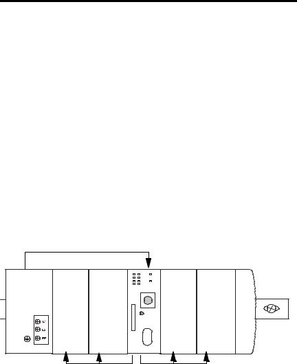
About the Power Supplies in a CompactLogix System
The CompactLogix system is set up differently than other Logix systems. The following are considerations specific to the CompactLogix system:
1768 CompactLogix System
Power supply provides 24V dc power to controller through the backplane.
Power
Supply
|
|
Controller |
|
|
Communicationor |
Motion Module |
Communicationor Motion Module |
1769 I/O Module |
1769 I/O Module |
|
Controller provides 5V dc |
Controller provides |
|
|
|
to communication and |
5V/24V dc to 1769 I/O |
||
|
motion modules. |
modules. |
|
|
•Both the 1768-PA3 and the 1768-PB3 power supplies require that a 1768 CompactLogix controller be installed in the same bank as the power supply before the system is powered.
The power supply sends 24V dc to the controller located either immediately to the right of the power supply or immediately to the right of the communication and motion modules.
Publication 1768-IN001B-EN-P - July 2006

1768 CompactLogix Power Supplies 7
The controller converts the 24V dc to 5V dc and distributes 5V dc and 24V dc power as required by modules on the backplane. The following list describes controller power distribution considerations:
•5V/24V power goes to 1769 I/O modules on the right side of the controller.
•5V power goes to 1768 communication or motion modules on the left side of the controller.
•System power-up and power-down may take longer than expected.
•Full power-up should occur within a few seconds of turning on the power supply. Power-down, however, takes significantly longer. When the power supply is turned off, the CompactLogix controller uses some power to write its program to internal memory. During this program write, there is activity on the controller’s status indicators.
IMPORTANT |
When you turn the CompactLogix power supply off, make sure you wait for all |
|
status indicators on the power supply and controller to turn off before |
||
|
||
|
disconnecting any part from the system. |
|
|
If you disconnect the CompactLogix system while the controller is still writing |
|
|
its program to memory, the program write will not be completed and you will |
|
|
lose your program. |
|
|
|
•If your system is not receiving power, the cause may or may not be the power supply.
For example, if a 5V short exists in the 1769 I/O portion of the local chassis, the controller faults and stops powering the 1769 I/O until the short condition is corrected. In this case, the power supply is operating normally and continuing to send 24V dc to the controller.
To troubleshoot any power supply issues, see Interpret the LED Indicators.
•1769 CompactLogix I/O modules in the local chassis receive power from the 1768 power supply. However, banks of 1769 I/O modules remote to the 1768 power supply require that a 1769 power supply be installed in the remote bank.
IMPORTANT |
Never install a 1769 power supply on the local 1768 CompactLogix |
|
backplane. |
||
|
||
|
|
Publication 1768-IN001B-EN-P - July 2006

8 1768 CompactLogix Power Supplies
•The 1768 power supply has a different distance rating than the 1769 power supply. For more information, see Place 1769 I/O Modules in a 1768 CompactLogix System.
Use a Fuse with the Power Supply
The CompactLogix power supply has an internal, non-replaceable fuse soldered in place. This fuse is intended to guard against fire hazard due to short circuit conditions. We recommend you put a user-replaceable fuse in line between incoming power and the power supply terminal block.
User Power Overcurrent Condition
In the event of an overcurrent condition, the power supply outputs latch off and remain off until the overcurrent is removed and the power is cycled. Reload the your program following a power supply shutdown.
ATTENTION
To avoid unexpected operation due to 24V dc user-power shutdown, monitor the 24V dc user output with a 24V dc input channel.
Publication 1768-IN001B-EN-P - July 2006
1768 CompactLogix Power Supplies 9
1768-PA3 Power Dissipation and Requirements
The following tables show power dissipation and input power requirements of the
1768-PA3 power supply. |
|
|
|
|
|
|
|
|
|||
1768-PA3 Power Dissipation |
|
|
|
|
|
|
|
|
|||
|
35 W |
|
|
|
|
|
|
|
|
|
|
|
|
|
|
|
|
|
|
|
|
30 W |
|
|
30 W |
|
|
|
|
|
|
|
|
|
90 W |
|
|
|
|
|
|
|
|
|
|
|
|
Power |
25 W |
|
|
|
|
|
|
|
|
|
|
|
|
|
|
|
|
|
|
|
|
|
|
Dissipated |
20 W |
|
|
|
|
|
|
|
|
|
|
(Watts) |
|
|
|
|
|
|
|
|
|
|
|
|
|
|
|
|
|
|
|
|
|
|
|
|
15 W |
12 W |
|
|
|
|
|
|
|
|
|
|
|
|
|
|
|
|
|
|
|
||
|
10 W |
|
6 W |
|
|
|
|
|
|
|
|
|
|
|
|
|
|
|
|
|
|
|
|
|
5 W |
|
|
|
|
|
|
|
|
|
|
|
0 W |
|
10 W |
20 W |
30 W |
40 W |
50W |
60 W |
70 W |
80 W |
90 W |
|
0 W |
||||||||||
Output Power (Watts)
1768-PA3 Input Power
Requirements
|
90 W |
|
|
|
|
|
|
|
|
|
|
|
|
|
|
|
90 W 118 W |
|
|
|
80 W |
|
|
|
|
|
|
|
|
|
70 W |
|
|
|
|
|
|
|
|
|
|
|
|
|
|
|
|
|
|
|
60 W |
|
|
|
|
|
|
|
|
|
|
|
|
|
|
|
|
|
|
Total Output |
50 W |
|
|
|
|
|
|
|
|
|
|
|
|
|
|
|
|
||
Power |
40 W |
|
|
|
|
|
|
|
|
|
|
|
|
|
|
|
|
||
Backplane Plus |
30 W |
|
|
|
|
|
|
|
|
Auxiliary |
|
|
|
|
|
|
|
|
|
20 W |
|
|
|
|
|
|
|
|
|
(Watts) |
|
|
|
|
|
|
|
|
|
|
|
|
|
|
|
|
|
||
|
|
|
|
|
|
|
|
|
|
|
10 W |
|
|
|
|
|
|
|
|
|
6 W |
|
|
|
|
|
|
|
|
|
0 W |
|
|
|
|
|
|
|
|
|
|
18 W |
|
||||||
|
|
0 W |
20 W 40 W 60 W 80 W 100 W 120 W |
||||||
|
|
|
|
|
Input Power (Watts) |
||||
Publication 1768-IN001B-EN-P - July 2006
10 1768 CompactLogix Power Supplies
1768-PB3 Power Dissipation and Requirements
The following tables show power dissipation and input power requirements of the
1768-PB3 power supply. |
|
|
|
|
|
|
|
1768-PB3 Power Dissipation |
|
|
|
|
|
||
|
35 W |
|
|
|
|
|
|
|
30 W |
|
|
|
|
|
|
|
25 W |
|
|
|
|
|
|
Power |
20 W |
|
|
|
|
22 W |
|
Dissipated |
|
|
|
|
|
|
|
|
|
|
|
|
|
|
|
(Watts) |
15 W |
|
|
|
|
|
|
|
|
|
|
|
|
|
|
|
10 W |
|
|
|
|
|
|
|
10 W |
6 W |
|
|
|
|
|
|
|
|
|
|
|
|
|
|
5 W |
|
|
|
|
|
|
|
0 W |
|
|
|
|
|
|
|
0 W |
10 W |
20 W |
30 W 40 W 50W 60 W |
70 W |
80 W |
90 W |
|
|
|
|
Output Power (Watts) |
|
|
|
1768-PB3 Input Power
Requirements
|
90 W |
|
|
|
|
|
|
|
|
|
|
|
|
|
|
112 W |
|
|
80 W |
|
|
|
|
|
|
|
|
|
|
|
|
|
|
|
|
Total Output |
70 W |
|
|
|
|
|
|
|
|
|
|
|
|
|
|
||
60 W |
|
|
|
|
|
|
|
|
Power |
|
|
|
|
|
|
|
|
Backplane Plus |
50 W |
|
|
|
|
|
|
|
|
|
|
|
|
|
|
||
Auxiliary |
|
|
|
|
|
|
|
|
40 W |
|
|
|
|
|
|
|
|
(Watts) |
|
|
|
|
|
|
|
|
|
|
|
|
|
|
|
|
|
|
30 W |
|
|
|
|
|
|
|
|
|
|
|
|
|
|
|
|
|
20 W |
|
|
|
|
|
|
|
|
|
|
|
|
|
|
|
|
|
10 W |
|
|
|
|
|
|
|
|
|
6 W |
|
|
|
|
|
|
|
0 W |
|
16 W |
|||||
|
0 W |
20 W 40 W 60 W 80 W 100 W 120 W |
||||||
Input Power (Watts)
Publication 1768-IN001B-EN-P - July 2006
Loading...