


 Loading...
1768 CompactLogix System
Catalog Numbers 1768-L43 and 1768-L45 CompactLogix Controllers
Quick Start
Important User Information
Solid state equipment has operational characteristics differing from those of electromechanical equipment. Safety Guidelines for the Application, Installation and Maintenance of Solid State Controls (publication SGI-1.1 available from your local Rockwell Automation sales office or online at http://www.rockwellautomation.com/literature/) describes some important differences between solid state equipment and hard-wired electromechanical devices. Because of this difference, and also because of the wide variety of uses for solid state equipment, all persons responsible for applying this equipment must satisfy themselves that each intended application of this equipment is acceptable.
In no event will Rockwell Automation, Inc. be responsible or liable for indirect or consequential damages resulting from the use or application of this equipment.
The examples and diagrams in this manual are included solely for illustrative purposes. Because of the many variables and requirements associated with any particular installation, Rockwell Automation, Inc. cannot assume responsibility or liability for actual use based on the examples and diagrams.
No patent liability is assumed by Rockwell Automation, Inc. with respect to use of information, circuits, equipment, or software described in this manual.
Reproduction of the contents of this manual, in whole or in part, without written permission of Rockwell Automation, Inc., is prohibited.
Throughout this manual, when necessary, we use notes to make you aware of safety considerations.
WARNING
Identifies information about practices or circumstances that can cause an explosion in a hazardous environment, which may lead to personal injury or death, property damage, or economic loss.
IMPORTANT Identifies information that is critical for successful application and understanding of the product.
ATTENTION
Identifies information about practices or circumstances that can lead to personal injury or death, property damage, or economic loss. Attentions help you identify a hazard, avoid a hazard, and recognize the consequence
SHOCK HAZARD
Labels may be on or inside the equipment, for example, a drive or motor, to alert people that dangerous voltage may be present.
BURN HAZARD
Labels may be on or inside the equipment, for example, a drive or motor, to alert people that surfaces may reach dangerous temperatures.
Allen-Bradley, Rockwell Automation, Rockwell Software, Inc., CompactLogix, ControlLogix, FactoryTalk ME, Kinetix, Logix5000, Point I/O, Panelview Plus, PowerFlex, RSLinx, RSLinx Classic, RSLinx Enterprise, RSLogix, RSLogix 5000, RSLogix 5000 with PhaseManager, RSView Machine Edition, RSView ME, RSView SE, RSView Studio, RSView Enterprise, and TechConnect are trademarks of Rockwell Automation, Inc.
Trademarks not belonging to Rockwell Automation are property of their respective companies.
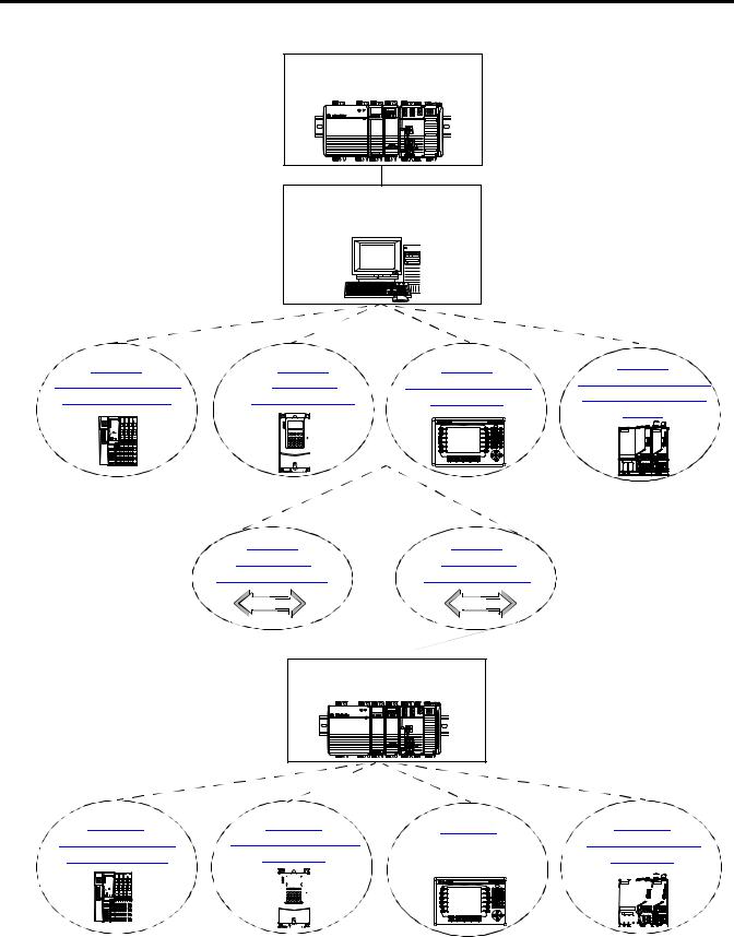
Where to Start
Follow the path that matches your hardware and network configuration.
Chapter 1
Prepare the CompactLogix
Hardware
Required
Chapter 2
Prepare the Computer and Load
Controller Firmware
Required
Optional
depending on your system
Optional
depending on your network
Chapter 9
Create a Project in RSLogix 5000
Required
Optional
depending on your system
|
|
|
|
|
|
|
|
|
|
|
|
|
|
|
|
|
|
|
|
|
|
|
|
|
|
|
|
|
|
|
|
|
|
|
|
|
|
|
|
|
|
|
|
|
|
|
|
|
|
|
|
|
|
|
|
|
|
|
|
|
|
|
|
|
|
|
|
|
|
|
|
|
|
|
|
|
|
|
|
|
|
|
|
|
|
|
|
|
|
|
|
|
|
|
|
|
|
|
|
|
|
|
|
|
|
|
|
|
|
|
|
|
|
|
|
|
|
|
|
|
|
|
|
|
Publication IASIMP-QS003B-EN-P - October 2009 |
3 |
|||||||||||||||||||||||
Where to Start
How Hardware Is Connected
This quick start demonstrates CompactLogix L43 and L45 control systems using a single EtherNet/IP or DeviceNet network for cost-effectiveness and simplified setup. You may choose to use a multiple network system requiring a combination of EtherNet/IP and DeviceNet procedures shown in this quick start.
Rockwell Automation also offers many devices other than those in the examples. See your local Rockwell Automation representative for other device options.
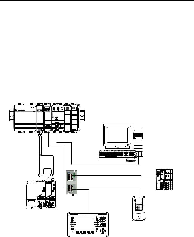
Option 1: 1768-L43 and 1768-L45 Systems with EtherNet/IP Network
1768-L43 CompactLogix Controller with 1768-ENBT EtherNet/IP and 1768-M04SE SERCOS Modules
Serial |
EtherNet/IP |
SERCOS |
Computer with Ethernet Port
1756-CP3
Distributed POINT I/O with 1734-AENT Adapter
Ethernet Switch


 2094 Kinetix
 6000
6000


Multi-axis Servo Drive System
PowerFlex 70 Drive with 20-COMM-E Adapter
2711P PanelView Plus Terminal
with Built-in EtherNet/IP Port
4 |
Publication IASIMP-QS003B-EN-P - October 2009 |
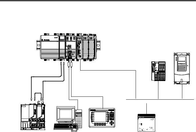
Where to Start
Option 2: 1768-L43 and L45 Systems with DeviceNet Network
1768-L43 CompactLogix Controller with 1768-M04SE SERCOS and 1769-SDN DeviceNet Modules
PowerFlex 70 Drive with 20-COMM-D Adapter
Distributed POINT I/O with 1734-ADN Adapter
DeviceNet
SERCOS
Serial
2706-NC13
1756-CP3 


 DeviceNet with KwikLink
flat cable and micro connectors
2094 Kinetix 6000 |
Computer |
2711P PanelView Plus Terminal |
|
DeviceNet Power Supply |
|||
Multi-axis Servo Drive System |
|||
|
|||
|
1606-XLDNET8 |
||
|
|
Publication IASIMP-QS003B-EN-P - October 2009 |
5 |
Where to Start
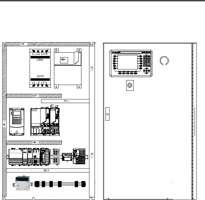
Sample System Panel Layout
The sample panel layout shows the general orientation of 1768-L43 and 1768-L45 system components for both EtherNet/IP and DeviceNet networks used in this quick start.
AC Line |
|
Filter |
Line Interface |
|
|
|
Module |
PowerFlex 70 |
|
Kinetix 6000 Drive Modules |
|
1768-L43 CompactLogix System |
Distributed POINT I/O |
|
1794-PS3 |
Ethernet Switch |
|
DeviceNet KwikLink System |
|
DeviceNet Power Supply |
|
PanelView Plus |
Through-the-door |
Disconnect |
E-Stop |
For additional panel layout assistance, the Kinetix Accelerator Toolkit CD in Appendix B provides CAD enclosure, component, and wiring diagrams, in DXF format, for most Rockwell Automation motion components. Refer to the System Design for Control of Electrical Noise Reference Manual, publication GMC-RM001, for best practice techniques.
For panel layout instructions specific to the Kinetix 6000 drives, refer to the Kinetix 6000 Installation Manual, publication 2094-IN001.
6 |
Publication IASIMP-QS003B-EN-P - October 2009 |

Table of Contents
Prepare the CompactLogix
Hardware
Prepare the Computer and Load
Controller Firmware
Preface
About This Publication . . . . . . . . . . . . . . . . . . . . . . . . . . . . . . . . . . . . . 13 Audience . . . . . . . . . . . . . . . . . . . . . . . . . . . . . . . . . . . . . . . . . . . . . . . . . 14 Required Software . . . . . . . . . . . . . . . . . . . . . . . . . . . . . . . . . . . . . . . . . 14 Parts List: Option 1, 1768-L43 System with EtherNet/IP . . . . . . . . . 15 Parts List: Option 2, 1768-L43 System with DeviceNet . . . . . . . . . . . 17 Conventions . . . . . . . . . . . . . . . . . . . . . . . . . . . . . . . . . . . . . . . . . . . . . . 19
Chapter 1
Introduction . . . . . . . . . . . . . . . . . . . . . . . . . . . . . . . . . . . . . . . . . . . . . . 21
Before You Begin. . . . . . . . . . . . . . . . . . . . . . . . . . . . . . . . . . . . . . . . . . 21
What You Need . . . . . . . . . . . . . . . . . . . . . . . . . . . . . . . . . . . . . . . . . . . 21
Follow These Steps . . . . . . . . . . . . . . . . . . . . . . . . . . . . . . . . . . . . . . . . 22
About the 1768 CompactLogix Controller . . . . . . . . . . . . . . . . . . . . . . 23
Mount and Wire the Line Interface Module . . . . . . . . . . . . . . . . . . . . . 24
Assemble the 1768 CompactLogix System. . . . . . . . . . . . . . . . . . . . . . 25
Make EtherNet/IP Network Connection. . . . . . . . . . . . . . . . . . . . . . . 28
Make DeviceNet Network Connections. . . . . . . . . . . . . . . . . . . . . . . . 29
Wire the 1768-PA3 Power Supply. . . . . . . . . . . . . . . . . . . . . . . . . . . . . 32
Additional Resources . . . . . . . . . . . . . . . . . . . . . . . . . . . . . . . . . . . . . . . 33
Chapter 2
Introduction . . . . . . . . . . . . . . . . . . . . . . . . . . . . . . . . . . . . . . . . . . . . . . 35 Before You Begin. . . . . . . . . . . . . . . . . . . . . . . . . . . . . . . . . . . . . . . . . . 35 What You Need . . . . . . . . . . . . . . . . . . . . . . . . . . . . . . . . . . . . . . . . . . . 35 Follow These Steps . . . . . . . . . . . . . . . . . . . . . . . . . . . . . . . . . . . . . . . . 36 Terminology . . . . . . . . . . . . . . . . . . . . . . . . . . . . . . . . . . . . . . . . . . . . . . 37 Make Network Connections for Personal Computer. . . . . . . . . . . . . . 38 Install RSLogix Programming Software . . . . . . . . . . . . . . . . . . . . . . . . 39 Configure a Serial Driver . . . . . . . . . . . . . . . . . . . . . . . . . . . . . . . . . . . . 44 Set the IP Address for the Computer . . . . . . . . . . . . . . . . . . . . . . . . . . 46 Configure the EtherNet/IP Driver in RSLinx Software . . . . . . . . . . . 48 Load the Controller Firmware. . . . . . . . . . . . . . . . . . . . . . . . . . . . . . . . 49 Install Additional Software . . . . . . . . . . . . . . . . . . . . . . . . . . . . . . . . . . 52 Additional Resources . . . . . . . . . . . . . . . . . . . . . . . . . . . . . . . . . . . . . . . 52
Prepare the Distributed POINT I/O
Hardware
Chapter 3
Introduction . . . . . . . . . . . . . . . . . . . . . . . . . . . . . . . . . . . . . . . . . . . . . . 53 Before You Begin. . . . . . . . . . . . . . . . . . . . . . . . . . . . . . . . . . . . . . . . . . 53 What You Need . . . . . . . . . . . . . . . . . . . . . . . . . . . . . . . . . . . . . . . . . . . 53 Follow These Steps . . . . . . . . . . . . . . . . . . . . . . . . . . . . . . . . . . . . . . . . 54 Mount and Connect the Network Adapter. . . . . . . . . . . . . . . . . . . . . . 55 Mount the POINT I/O Modules . . . . . . . . . . . . . . . . . . . . . . . . . . . . . 57 Mount and Wire the POINT I/O Power Supply. . . . . . . . . . . . . . . . . 58 Wire the Adapter and I/O Modules to the Power Supply. . . . . . . . . . 59 Additional Resources . . . . . . . . . . . . . . . . . . . . . . . . . . . . . . . . . . . . . . . 60
Publication IASIMP-QS003B-EN-P - October 2009

Table of Contents
Chapter 4
Prepare the PowerFlex 70 Drive Introduction . . . . . . . . . . . . . . . . . . . . . . . . . . . . . . . . . . . . . . . . . . . . . . 61 Before You Begin. . . . . . . . . . . . . . . . . . . . . . . . . . . . . . . . . . . . . . . . . . 61 What You Need . . . . . . . . . . . . . . . . . . . . . . . . . . . . . . . . . . . . . . . . . . . 61 Follow These Steps . . . . . . . . . . . . . . . . . . . . . . . . . . . . . . . . . . . . . . . . 62 Mount and Wire the PowerFlex 70 Drive. . . . . . . . . . . . . . . . . . . . . . . 63 Configure the Communication Adapter . . . . . . . . . . . . . . . . . . . . . . . . 65 Connect Communication Adapter to the PowerFlex 70 Drive . . . . . . 66 Additional Resources . . . . . . . . . . . . . . . . . . . . . . . . . . . . . . . . . . . . . . . 68
Prepare the PanelView Plus
Terminal
Chapter 5
Introduction . . . . . . . . . . . . . . . . . . . . . . . . . . . . . . . . . . . . . . . . . . . . . . 69 Before You Begin. . . . . . . . . . . . . . . . . . . . . . . . . . . . . . . . . . . . . . . . . . 69 What You Need . . . . . . . . . . . . . . . . . . . . . . . . . . . . . . . . . . . . . . . . . . . 69 Follow These Steps . . . . . . . . . . . . . . . . . . . . . . . . . . . . . . . . . . . . . . . . 70 Mount and Wire the PanelView Plus Terminal . . . . . . . . . . . . . . . . . . 71 Make Network Connections for PanelView Plus . . . . . . . . . . . . . . . . . 72 Assign IP Address for PanelView Plus . . . . . . . . . . . . . . . . . . . . . . . . . 73 Upgrade Terminal Firmware . . . . . . . . . . . . . . . . . . . . . . . . . . . . . . . . . 75 Additional Resources . . . . . . . . . . . . . . . . . . . . . . . . . . . . . . . . . . . . . . . 76
Prepare the Kinetix 6000
Multi-axis Servo Drive System
Configure the EtherNet/IP
Network
Chapter 6
Introduction . . . . . . . . . . . . . . . . . . . . . . . . . . . . . . . . . . . . . . . . . . . . . . 77 Before You Begin. . . . . . . . . . . . . . . . . . . . . . . . . . . . . . . . . . . . . . . . . . 77 What You Need . . . . . . . . . . . . . . . . . . . . . . . . . . . . . . . . . . . . . . . . . . . 77 Follow These Steps . . . . . . . . . . . . . . . . . . . . . . . . . . . . . . . . . . . . . . . . 78 Mount and Bond the Power Rail. . . . . . . . . . . . . . . . . . . . . . . . . . . . . . 79 Mount the Integrated Axis and Axis Module . . . . . . . . . . . . . . . . . . . . 80 Wire Power to the Integrated Axis Module . . . . . . . . . . . . . . . . . . . . . 82 Wire Servo Motors to Integrated Axis and Axis Modules . . . . . . . . . . 83 Connect the SERCOS Fiber Optic Cables . . . . . . . . . . . . . . . . . . . . . . 84 Set the SERCOS Node Address . . . . . . . . . . . . . . . . . . . . . . . . . . . . . . 85 Additional Resources . . . . . . . . . . . . . . . . . . . . . . . . . . . . . . . . . . . . . . . 86
Chapter 7
Introduction . . . . . . . . . . . . . . . . . . . . . . . . . . . . . . . . . . . . . . . . . . . . . . 87
Before You Begin. . . . . . . . . . . . . . . . . . . . . . . . . . . . . . . . . . . . . . . . . . 87
What You Need . . . . . . . . . . . . . . . . . . . . . . . . . . . . . . . . . . . . . . . . . . . 87
Follow These Steps . . . . . . . . . . . . . . . . . . . . . . . . . . . . . . . . . . . . . . . . 88
Terminology . . . . . . . . . . . . . . . . . . . . . . . . . . . . . . . . . . . . . . . . . . . . . . 88
Assign IP Addresses. . . . . . . . . . . . . . . . . . . . . . . . . . . . . . . . . . . . . . . . 89
Browse the EtherNet/IP Network in RSLinx Classic Software . . . . . 91
Additional Resources . . . . . . . . . . . . . . . . . . . . . . . . . . . . . . . . . . . . . . . 92
8 |
Publication IASIMP-QS003B-EN-P - October 2009 |

Table of Contents
Chapter 8
Configure the DeviceNet Network Introduction . . . . . . . . . . . . . . . . . . . . . . . . . . . . . . . . . . . . . . . . . . . . . . 93 Before You Begin. . . . . . . . . . . . . . . . . . . . . . . . . . . . . . . . . . . . . . . . . . 93 What You Need . . . . . . . . . . . . . . . . . . . . . . . . . . . . . . . . . . . . . . . . . . . 93 Follow These Steps . . . . . . . . . . . . . . . . . . . . . . . . . . . . . . . . . . . . . . . . 94 Apply Power to the DeviceNet Network . . . . . . . . . . . . . . . . . . . . . . . 94 Set the Node Address of the DeviceNet Scanner . . . . . . . . . . . . . . . . 95 Create a DeviceNet Configuration File. . . . . . . . . . . . . . . . . . . . . . . . . 97 Additional Resources . . . . . . . . . . . . . . . . . . . . . . . . . . . . . . . . . . . . . . 100
Create a Project in RSLogix 5000
Programming Software
Chapter 9
Introduction . . . . . . . . . . . . . . . . . . . . . . . . . . . . . . . . . . . . . . . . . . . . . 101 Before You Begin. . . . . . . . . . . . . . . . . . . . . . . . . . . . . . . . . . . . . . . . . 101 What You Need . . . . . . . . . . . . . . . . . . . . . . . . . . . . . . . . . . . . . . . . . . 101 Follow These Steps . . . . . . . . . . . . . . . . . . . . . . . . . . . . . . . . . . . . . . . 102 Create a Project . . . . . . . . . . . . . . . . . . . . . . . . . . . . . . . . . . . . . . . . . . 103 Configure 1768-ENBT Ethernet Module. . . . . . . . . . . . . . . . . . . . . . 104 Configure 1769-SDN DeviceNet Module . . . . . . . . . . . . . . . . . . . . . 105 Configure 1769 Local I/O Modules . . . . . . . . . . . . . . . . . . . . . . . . . . 107 Verify I/O Configuration . . . . . . . . . . . . . . . . . . . . . . . . . . . . . . . . . . 108 Add Ladder Logic to Test Local 1769 Compact I/O Modules. . . . . 109 Set the Project Path and Download to the Controller . . . . . . . . . . . . 112 Additional Resources . . . . . . . . . . . . . . . . . . . . . . . . . . . . . . . . . . . . . . 114
Add Distributed Point I/O Modules to the Project
Chapter 10
Introduction . . . . . . . . . . . . . . . . . . . . . . . . . . . . . . . . . . . . . . . . . . . . . 115
Before You Begin. . . . . . . . . . . . . . . . . . . . . . . . . . . . . . . . . . . . . . . . . 115
What You Need . . . . . . . . . . . . . . . . . . . . . . . . . . . . . . . . . . . . . . . . . . 115
Follow These Steps . . . . . . . . . . . . . . . . . . . . . . . . . . . . . . . . . . . . . . . 116
Add Distributed I/O Modules . . . . . . . . . . . . . . . . . . . . . . . . . . . . . . 117
Configure the DeviceNet Subnet . . . . . . . . . . . . . . . . . . . . . . . . . . . . 120
Configure the 1734-ADN Properties . . . . . . . . . . . . . . . . . . . . . . . . . 123
Create a DeviceNet Scanlist. . . . . . . . . . . . . . . . . . . . . . . . . . . . . . . . . 126
Add Ladder Logic . . . . . . . . . . . . . . . . . . . . . . . . . . . . . . . . . . . . . . . . 128
Create DeviceNet Tags and Add Ladder Logic . . . . . . . . . . . . . . . . . 130
Download the Project . . . . . . . . . . . . . . . . . . . . . . . . . . . . . . . . . . . . . 135
Test the Distributed I/O Light . . . . . . . . . . . . . . . . . . . . . . . . . . . . . . 136
Additional Resources . . . . . . . . . . . . . . . . . . . . . . . . . . . . . . . . . . . . . . 136
Publication IASIMP-QS003B-EN-P - October 2009 |
9 |

Table of Contents
Chapter 11
Create a PowerFlex 70 Application Introduction . . . . . . . . . . . . . . . . . . . . . . . . . . . . . . . . . . . . . . . . . . . . . 137 Before You Begin. . . . . . . . . . . . . . . . . . . . . . . . . . . . . . . . . . . . . . . . . 137 What You Need . . . . . . . . . . . . . . . . . . . . . . . . . . . . . . . . . . . . . . . . . . 137 Follow These Steps . . . . . . . . . . . . . . . . . . . . . . . . . . . . . . . . . . . . . . . 138 Add the Drive to Your RSLogix 5000 Project . . . . . . . . . . . . . . . . . . 139 Edit the Drive Parameters . . . . . . . . . . . . . . . . . . . . . . . . . . . . . . . . . . 143 Create a DeviceNet Scanlist. . . . . . . . . . . . . . . . . . . . . . . . . . . . . . . . . 145 Create DeviceNet Tags . . . . . . . . . . . . . . . . . . . . . . . . . . . . . . . . . . . . 149 Download the Project . . . . . . . . . . . . . . . . . . . . . . . . . . . . . . . . . . . . . 152 Test the PowerFlex 70 Tags . . . . . . . . . . . . . . . . . . . . . . . . . . . . . . . . 153 Additional Resources . . . . . . . . . . . . . . . . . . . . . . . . . . . . . . . . . . . . . . 159
Create a PanelView Plus
Application
Chapter 12
Introduction . . . . . . . . . . . . . . . . . . . . . . . . . . . . . . . . . . . . . . . . . . . . . 161 Before You Begin. . . . . . . . . . . . . . . . . . . . . . . . . . . . . . . . . . . . . . . . . 161 What You Need . . . . . . . . . . . . . . . . . . . . . . . . . . . . . . . . . . . . . . . . . . 161 Follow These Steps . . . . . . . . . . . . . . . . . . . . . . . . . . . . . . . . . . . . . . . 162 Create a New Application . . . . . . . . . . . . . . . . . . . . . . . . . . . . . . . . . . 163 Create an RSLinx Enterprise Configuration in
FactoryTalkView ME . . . . . . . . . . . . . . . . . . . . . . . . . . . . . . . . . . . 164 Create Device Shortcuts to the Controller . . . . . . . . . . . . . . . . . . . . . 166 Create the OB16_Light Indicator . . . . . . . . . . . . . . . . . . . . . . . . . . . . 170 Create a Push Button . . . . . . . . . . . . . . . . . . . . . . . . . . . . . . . . . . . . . . 173 Test the Indicator and Push Button . . . . . . . . . . . . . . . . . . . . . . . . . . 175 Add a Goto Configuration Mode Button . . . . . . . . . . . . . . . . . . . . . . 176 Assign Keys . . . . . . . . . . . . . . . . . . . . . . . . . . . . . . . . . . . . . . . . . . . . . 177 Assign an Initial Screen . . . . . . . . . . . . . . . . . . . . . . . . . . . . . . . . . . . . 178 Transfer the Application to the PanelView Plus Terminal. . . . . . . . . 179 Test the Application on the PanelView Plus Terminal . . . . . . . . . . . 181 Additional Resources . . . . . . . . . . . . . . . . . . . . . . . . . . . . . . . . . . . . . . 182
Chapter 13
Create a Kinetix 6000 Application Introduction . . . . . . . . . . . . . . . . . . . . . . . . . . . . . . . . . . . . . . . . . . . . . 183
Before You Begin. . . . . . . . . . . . . . . . . . . . . . . . . . . . . . . . . . . . . . . . . 183
What You Need . . . . . . . . . . . . . . . . . . . . . . . . . . . . . . . . . . . . . . . . . . 183
Follow These Steps . . . . . . . . . . . . . . . . . . . . . . . . . . . . . . . . . . . . . . . 184
Enable Coordinated System Time Master . . . . . . . . . . . . . . . . . . . . . 185
Create the Motion Group . . . . . . . . . . . . . . . . . . . . . . . . . . . . . . . . . . 186
Configure Your Logix SERCOS Module . . . . . . . . . . . . . . . . . . . . . . 187
Configure Your Kinetix IAM and AM Modules . . . . . . . . . . . . . . . . 189
Configure Axis Properties . . . . . . . . . . . . . . . . . . . . . . . . . . . . . . . . . . 192
Save and Download Your Program. . . . . . . . . . . . . . . . . . . . . . . . . . . 193
Test the Kinetix Application File . . . . . . . . . . . . . . . . . . . . . . . . . . . . 195
Additional Resources . . . . . . . . . . . . . . . . . . . . . . . . . . . . . . . . . . . . . . 196
10 |
Publication IASIMP-QS003B-EN-P - October 2009 |
|
|
Table of Contents |
|
Appendix A |
|
Network Information |
Network Information. . . . . . . . . . . . . . . . . . . . . . . . . . . . . . . |
. . . . . . . 197 |
|
Appendix B |
|
Kinetix Accelerator Toolkit |
Sample Panel Layout . . . . . . . . . . . . . . . . . . . . . . . . . . . . |
. . . . . . . 199 |
|
Simplified Wiring . . . . . . . . . . . . . . . . . . . . . . . . . . . . . . . |
. . . . . . . 199 |
|
Preconfigured HMI . . . . . . . . . . . . . . . . . . . . . . . . . . . . . |
. . . . . . . 199 |
|
Preconfigured Logic. . . . . . . . . . . . . . . . . . . . . . . . . . . . . |
. . . . . . . 199 |
|
Diagnostic Tools . . . . . . . . . . . . . . . . . . . . . . . . . . . . . . . |
. . . . . . . 200 |
|
Kinetix Accelerator Toolkit CD . . . . . . . . . . . . . . . . . . . |
. . . . . . . 200 |
|
Appendix C |
|
Motion Anaylzer |
Motion Analyzer. . . . . . . . . . . . . . . . . . . . . . . . . . . . . . . . . . . |
. . . . . . . 201 |
Publication IASIMP-QS003B-EN-P - October 2009 |
11 |

Table of Contents
12 |
Publication IASIMP-QS003B-EN-P - October 2009 |

Preface
About This Publication
This quick start provides examples and procedures for 1768-L43 and 1768-L45 CompactLogix systems. It includes version 18 release updates for RSLogix 5000 programming software. These procedures cover many common user tasks, such as:
•connecting the controller to multiple devices including local and distributed I/O, drives, Kinetix 6000 servo drives, and a PanelView Plus terminal.
•connecting and configuring EtherNet/IP, DeviceNet, and serial networks using CompactLogix systems.
•creating and monitoring controller programs.
The examples are designed to get devices installed and communicating with each other in the simplest way possible. The programming examples are not complex, and offer easy solutions to verify that devices are communicating properly.
The beginning of each chapter contains the following information. Read these sections carefully before beginning work in each chapter.
•Before You Begin - This section lists the steps that must be completed and decisions that must be made before starting that chapter. Because the chapters in this quick start do not have to be completed in the order in which they appear, this section defines the minimum amount of preparation required before completing the current chapter.
•What You Need - This section lists the tools that are required to complete the steps in the current chapter. This includes, but is not limited to, hardware and software.
•Follow These Steps - This section illustrates the steps in the current chapter and identifies which steps are required to complete the examples using specific networks.
Also note that the electronic version of this publication contains links to pages within publications for easier navigation. Click on any chapter title, chapter number, topic title, or page number to follow a link to the item.
Publication IASIMP-QS003B-EN-P - October 2009 |
13 |

Audience
This quick start was created to assist experienced or new industrial control users not familiar with the CompactLogix controllers or Integrated Architecture products of Rockwell Automation.
Required Software
The table lists software required to complete the examples in this quick start. Some software is required regardless of the 1768 CompactLogix system you use and other software is dependent on the network and devices in the system.
Rockwell Automation |
Version |
Required for |
|
|
|
|
|
RSLogix 5000 programming software |
18 |
All 1768-L43 and 1768-L45 |
|
systems |
|||
|
|
||
|
|
|
|
RSNetWorx for DeviceNet software |
7.0 |
DeviceNet network |
|
|
|
|
|
FactoryTalkView Machine Edition software |
|
|
|
Includes: |
|
|
|
• Factory Talk Services |
|
PanelView Plus terminals |
|
• RSLinx Enterprise |
|
|
|
• RSLinx Lite (Classic) |
|
|
|
|
|
|
14 |
Publication IASIMP-QS003B-EN-P - October 2009 |

Parts List: Option 1, 1768-L43 and 1768-L45 Systems with EtherNet/IP
The table lists the parts for the 1768-L43 and 1768-L45 systems with an EtherNet/IP network and a 200/230V Kinetix 6000 Multi-axis Servo Drive System.
Parts List: Option 1, 1768-L43 and 1768-L45 Systems with EtherNet/IP Network
|
Quantity |
Catalog Number |
Description |
|
|
|
|
General Configuration |
|
|
|
|
|
|
|
|
1 |
1768-L43 and 1768-L45 |
CompactLogix Controller |
|
|
|
|
|
1 |
1768-PA3 |
CompactLogix Power Supply |
|
|
|
|
|
1 |
1769-ECR |
Compact I/O Right End Cap/Terminator |
|
|
|
|
|
1 |
1769-IF4 |
Compact 4 Channel Analog Current/Voltage Input Module |
|
|
|
|
|
1 |
1769-IQ16 |
Compact 16 Point 24V dc Sinking/Sourcing Input Module |
|
|
|
|
|
1 |
1769-IF4XOF2 |
Compact 8 Bit Resolution, High Speed 4 In/2 Out Analog Combination Module |
|
|
|
|
|
1 |
1769-OF2 |
Compact 2 Channel Analog Current/Voltage Output Module |
|
|
|
|
|
1 |
1769-OB16 (1) |
Compact 16 Point 24V dc Sourcing Output Module |
|
1 |
1734-IB4 (2) |
POINT I/O 4 Sink Input Module |
|
1 |
1734-OB4E (2) (3) |
POINT I/O 4 Protected Output Module |
|
1 |
1734-OE2C (2) |
POINT I/O 2 Current Output Analog Module |
|
1 |
1734-TB |
Wiring Base w/ Removable IEC Screw Terminals (Quantity of 10) |
|
|
|
|
|
1 |
1794-PS13 |
FLEX I/O 85-264V ac to 24V dc 1.3A Power Supply |
|
|
|
|
|
1 |
20AB4P2A3AYNNNNN |
PowerFlex 70 Drive. |
|
|
|
|
|
1 |
2711P-B10C4D1 |
PanelView Plus 10 inch color keypad/touch terminal with EtherNet/IP and RS-232 |
|
|
|
|
|
1 |
1747-CP3 or 1756-CP3 |
RS-232 cable for connection between the 1768-L43 controller and personal computer |
|
|
|
|
|
1 |
64-134 |
DIN rail (steel not aluminum), 1 m |
|
|
|
|
|
EtherNet/IP Configuration |
|
|
|
|
|
|
|
1 |
1768-ENBT |
CompactLogix EtherNet/IP Communication Module |
|
|
|
|
|
1 |
1734-AENT |
POINT I/O Ethernet Adapter |
|
|
|
|
|
1 |
20-COMM-E |
PowerFlex 70 EtherNet/IP Adapter |
|
|
|
|
|
1 |
|
Ethernet Switch |
|
|
|
|
|
6 |
Non Rockwell Automation |
Ethernet CAT5 Straight-through cables |
|
|
|
|
Publication IASIMP-QS003B-EN-P - October 2009 |
15 |

Parts List: Option 1, 1768-L43 and 1768-L45 Systems with EtherNet/IP Network
|
Quantity |
Catalog Number |
Description |
|
|
|
|
Kinetix 6000 Servo Drive System - 200/230V (The quantity, size, and cat. nos. for the Kinetix equipment will vary by application motion requirements.)
|
1 |
1768-M04SE |
SERCOS interface module installs in 1768 CompactLogix controller and connects to |
|
|
Integrated Axis modules or Axis modules. |
|
|
|
|
|
|
|
|
|
|
1 |
2094-AL75S (4) |
Line Interface Module (LIM), 230V, 75 A |
|
1 |
140U-H-RVM12R |
Through-the-door Disconnect for LIM |
|
|
|
|
|
1 |
2090-XXLF-X330B |
Line Filter, 3-phase, 30 A ac |
|
|
|
|
|
1 |
2094-PRS2 |
Power Rail, 2-slot, Slim |
|
|
|
|
|
1 |
2094-AC09-M02 |
Integrated Axis Module (IAM), 6 kW Converter and 19 A Inverter Output |
|
|
|
|
|
1 |
2094-AM01 |
Axis Module (AM), 9 A Inverter Output |
|
|
|
|
|
1 |
MPL-A310P-MK22AA |
MP-Series Low Inertia Motor, 0.73 kW Output with Absolute, Multi-turn Feedback |
|
|
|
|
|
2 |
2090-XXNPMP-16S03 |
Motor Power Cable: 3 m (9.8 ft) |
|
|
|
|
|
2 |
2090-UXNFBMP-S03 |
Motor Feedback Cable, 3 m (9.8 ft) |
|
|
|
|
|
2 |
2090-SCEP0-9 |
SERCOS Fiber Optic Cable, 0.9 m (2.9 ft) |
|
|
|
|
|
1 |
2090-SCEP0-1 |
SERCOS Fiber Optic Cable, 0.1 m (5.1 in.) |
|
|
|
|
(1)The 1769-OB16 is the only Compact I/O module used in this quick start. The other modules are added as examples only and are not required.
(2)Use POINT I/O modules at series C or later to complete examples in this quick start.
(3)The 1734-OB4E module is the only POINT I/O module used in this quick start. The other modules are added as examples only and are not required.
(4)The 2094-AL75S line interface module (LIM) is optional. Individual components can be purchased separately instead of the LIM.
16 |
Publication IASIMP-QS003B-EN-P - October 2009 |

Parts List: Option 2, 1768-L43 and 1768-L45 Systems with DeviceNet
The table lists the parts for a 1768-L43 and 1768-L45 Systems with DeviceNet I/O, serial connections, and a 200/230V Kinetix 6000 Multi-axis Servo Drive System.
Parts List: Option 2, 1768-L43 and 1768-L45 Systems with DeviceNet Network
|
Quantity |
Catalog Number |
Description |
|
|
|
|
General |
Configuration |
|
|
|
|
|
|
|
1 |
1768-L43 and 1768-L45 |
CompactLogix Controller |
|
|
|
|
|
1 |
1768-PA3 |
CompactLogix Power Supply |
|
|
|
|
|
1 |
1769-ECR |
Compact I/O Right End Cap/Terminator |
|
|
|
|
|
1 |
1769-IF4 |
Compact 4 Channel Analog Current/Voltage Input Module |
|
|
|
|
|
1 |
1769-IQ16 |
Compact 16 Point 24V dc Sinking/Sourcing Input Module |
|
|
|
|
|
1 |
1769-IF4XOF2 |
Compact 8 Bit Resolution, High Speed 4 In/2 Out Analog Combination Module |
|
|
|
|
|
1 |
1769-OF2 |
Compact 2 Channel Analog Current/Voltage Output Module |
|
|
|
|
|
1 |
1769-OB16 (1) |
Compact 16 Point 24V dc Sourcing Output Module |
|
1 |
1734-IB4 (2) |
POINT I/O 4 Sink Input Module |
|
1 |
1734-OB4E (2) (3) |
POINT I/O 4 Protected Output Module |
|
1 |
1734-OE2C (2) |
POINT I/O 2 Current Output Analog Module |
|
1 |
1734-TB |
Wiring Base w/ Removable IEC Screw Terminals (Quantity of 10) |
|
|
|
|
|
1 |
1794-PS13 |
FLEX I/O 85-264V ac to 24V dc 1.3A Power Supply |
|
|
|
|
|
1 |
20AB4P2A3AYNNNNN |
PowerFlex 70 Drive |
|
|
|
|
|
1 |
2711P-B10C4D1 |
PanelView Plus 10 inch color keypad/touch terminal with EtherNet/IP and RS-232 |
|
|
|
|
|
1 |
1747-CP3 or 1756-CP3 |
RS-232 cable for connection between the 1768-L43 controller and personal computer |
|
|
|
|
|
1 |
2711-NC13 |
RS-232 cable for connection between the PanelView Plus terminal and the 1768-L43 |
|
|
|
controller or personal computer |
|
|
|
|
|
1 |
64-134 |
DIN rail (steel not aluminum), 1 m |
|
|
|
|
|
DeviceNet Configuration |
|
|
|
|
|
|
|
1 |
1769-SDN |
Compact DeviceNet Scanner |
|
|
|
|
|
1 |
1734-ADN |
POINT I/O DeviceNet Adapter |
|
|
|
|
|
1 |
20-COMM-D |
PowerFlex 70 DeviceNet Adapter |
|
|
|
|
|
1 |
1606-XLDNET8 |
DeviceNet Power Supply |
|
|
|
|
|
1 |
1485C-P1E75 |
KwikLink Flat Cable, 75 m |
|
|
|
|
|
2 |
1485A-T1E4 |
KwikLink Terminator/Resistor |
|
|
|
|
|
3 |
1485P-P1E4-R5 |
KwikLink Sealed Micro Connector |
|
|
|
|
|
3 |
1485K-P1F5-C |
KwikLink QD Cordset Micro Right-Angle Male |
|
|
|
|
|
1 |
1485T-P1E4-B1 |
KwikLink Power Tap Module |
|
|
|
|
Publication IASIMP-QS003B-EN-P - October 2009 |
17 |

Parts List: Option 2, 1768-L43 and 1768-L45 Systems with DeviceNet Network
|
Quantity |
Catalog Number |
Description |
|
|
|
|
Kinetix 6000 Servo Drive System - 200/230V (The quantity, size, and cat. nos. for the Kinetix equipment will vary by application motion requirements.)
|
1 |
1768-M04SE |
SERCOS interface module installs in 1768 CompactLogix controller and connects to |
|
|
Integrated Axis modules or Axis modules. |
|
|
|
|
|
|
|
|
|
|
1 |
2094-AL75S (4) |
Line Interface Module (LIM), 230V, 75 A |
|
1 |
140U-H-RVM12R |
Through-the-door Disconnect for LIM |
|
|
|
|
|
1 |
2090-XXLF-X330B |
Line Filter, 3-phase, 30 A ac |
|
|
|
|
|
1 |
2094-PRS2 |
Power Rail, 2-slot, Slim |
|
|
|
|
|
1 |
2094-AC09-M02 |
Integrated Axis Module (IAM), 6 kW Converter and 19 A Inverter Output |
|
|
|
|
|
1 |
2094-AM01 |
Axis Module (AM), 9 A Inverter Output |
|
|
|
|
|
1 |
MPL-A310P-MK22AA |
MP-Series Low Inertia Motor, 0.73 kW Output with Absolute, Multi-turn Feedback |
|
|
|
|
|
2 |
2090-XXNPMP-16S03 |
Motor Power Cable: 3 m (9.8 ft) |
|
|
|
|
|
2 |
2090-UXNFBMP-S03 |
Motor Feedback Cable, 3 m (9.8 ft) |
|
|
|
|
|
2 |
2090-SCEP0-9 |
SERCOS Fiber Optic Cable, 0.9 m (2.9 ft) |
|
|
|
|
|
1 |
2090-SCEP0-1 |
SERCOS Fiber Optic Cable, 0.1 m (5.1 in.) |
|
|
|
|
(1)The 1769-OB16 module is the only Compact I/O module used in this quick start. The other modules are added as examples only and are not required.
(2)Use POINT I/O modules at series C or later to complete examples in this quick start.
(3)The 1734-OB4E module is the only POINT I/O module used in this quick start. The other modules are added as examples only and are not required.
(4)The 2094-AL75S line interface module (LIM) is optional. Individual components can be purchased separately instead of the LIM.
18 |
Publication IASIMP-QS003B-EN-P - October 2009 |

Conventions
This manual uses the following conventions.
Convention |
Meaning |
Example |
|
|
|
|
|
Courier |
Type or enter text exactly as shown. |
Type cmd. |
|
font |
|||
|
|
||
Check or uncheck |
Click to activate or deactivate a checkbox. |
Check the Disable Keying checkbox. |
|
|
|
|
|
Click |
Click the left mouse button once while the cursor is positioned |
Click Browse. |
|
on object or selection. |
|||
|
|
||
|
|
|
|
Double-click |
Click the left mouse button twice in quick succession while the |
Double-click the application icon. |
|
cursor is positioned on object or selection. |
|||
|
|
||
|
|
|
|
Expand |
Click the + to the left of a given item /folder to show its |
Expand 1768 Bus under I/O Configuration. |
|
contents. |
|||
|
|
||
|
|
|
|
Right-click |
Click the right mouse button once while the cursor is positioned |
Right-click the 1768 Bus icon. |
|
on object or selection. |
|||
|
|
||
|
|
|
|
Select |
Click to highlight a menu item or list choice. |
Select New Module from the pull-down list. |
|
|
|
|
|
> |
Shows nested menu selections as menu name followed by menu |
Select File>Menu. |
|
|
selection. |
|
|
|
|
|
Publication IASIMP-QS003B-EN-P - October 2009 |
19 |

Notes:
20 |
Publication IASIMP-QS003B-EN-P - October 2009 |
Chapter 1
Prepare the CompactLogix Hardware
Introduction
In this chapter, you install your CompactLogix hardware including the controller, power supply, 1768 SERCOS module, and the 2094 line interface module. The line interface module will power the 1768 CompactLogix and Kinetix 6000 system components. Depending on your configuration, you also install the 1768 EtherNet/IP module, 1769 DeviceNet module, and local 1769 I/O modules.
Before You Begin
Determine which network and appropriate hardware to use.
•For an EtherNet/IP network (option 1), use the 1768-ENBT module with the controller.
•For a DeviceNet (option 2), use the 1769-SDN module with the controller.
•For a motion application (option 1 or 2), use a 1768-M04SE SERCOS module with the controller.
What You Need
•2094-AL75S line interface module (optional)
•1768-L43 or 1768-L45 CompactLogix controller
•1768-PA3 CompactLogix power supply
•1769-ECR end cap
•1768-ENBT EtherNet/IP module for an EtherNet/IP network (option 1)
–Ethernet switch and standard CAT5 Ethernet cable for EtherNet/IP network
•1768-M04SE SERCOS module for motion on either network (option 1 or 2)
•1769-SDN DeviceNet module for a DeviceNet network (option 2)
–1606-XLDNET8 power supply and KwikLink Power Tap module for DeviceNet network
–KwikLink right-angle male cables with sealed microconnectors, connected to a flat cable with terminator/resistor on each end for a DeviceNet network
•1769 Compact I/O modules
•Serial 1756-CP3 cable for EtherNet/IP and DeviceNet networks
Publication IASIMP-QS003B-EN-P - October 2009 |
21 |
Chapter 1 Prepare the CompactLogix Hardware
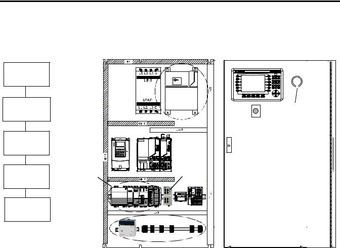
Follow These Steps
Complete the appropriate steps to assemble your 1768-L43/L45 CompactLogix hardware.
Mount and Wire |
|
|
|
|
the Line Interface |
|
|
||
Module |
|
|
|
|
|
page 24 |
|
Line Interface |
|
|
|
|
||
Assemble the 1768 |
|
Module |
||
CompactLogix |
|
|
Through-the-door |
|
|
|
Disconnect for |
||
System |
|
|
||
|
|
LIM Module |
||
|
page 25 |
|
||
|
|
|
||
Make EtherNet/IP |
|
|
||
Network |
|
|
|
|
Connection |
|
|
|
|
|
page 28 |
|
|
|
Make DeviceNet |
|
1768 |
Ethernet |
|
CompactLogix |
||||
Network |
Switch |
|||
|
System |
|||
Connections |
|
|
||
|
|
|
||
|
page 29 |
|
|
|
Wire the |
|
|
|
|
1768-PA3 Power |
|
|
|
|
Supply |
|
|
|
|
|
page 32 |
|
|
|
|
|
|
DeviceNet Network |
|
22 |
Publication IASIMP-QS003B-EN-P - October 2009 |
Prepare the CompactLogix Hardware |
Chapter 1 |
|
|
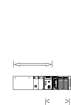
About the 1768 CompactLogix Controller
The 1768-L43 and 1768-L45 CompactLogix controllers combine a 1768 backplane and a 1769 backplane. The 1768 backplane supports the 1768 controller, the 1768 power supply, and a maximum of two 1768 modules, such as the EtherNet/IP module and the SERCOS interface module. The 1769 backplane supports 1769 modules, such as the 1769 DeviceNet module and 1769 I/O modules.
1768
|
|
|
|
|
|
|
|
1 Slot 2 Slot |
|
|
|
0 Slot |
|
|
|
|
|
|
|
|
|
|
|
|
|
|
|
|
|
|
|
|
|
|
|
|
|
|
|
|
|
|
|
|
|
|
|
|
|
|
|
|
|
|
|
|
|
|
|
|
|
|
|
|
|
|
|
|
|
|
|
|
|
|
|
|
|
|
|
|
|
|
|
0 Slot |
3 Slot 2 Slot 1 Slot |
||
|
|
|
|
|
|
|
|
|
|
1769 |
|
Publication IASIMP-QS003B-EN-P - October 2009 |
23 |
Chapter 1 Prepare the CompactLogix Hardware
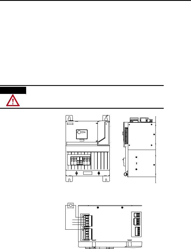
Mount and Wire the Line Interface Module
2094-AL75S or Equivalent Hardware, Required for EtherNet/IP and DeviceNet Systems
The line interface module (LIM) serves as the power connection and the generation point for the complete power needs of most control panels. The LIM module provides the control of three-phase power and the drive logic power, and also serves as the source and circuit protection of power for the controller, I/O, and other panel devices. A single LIM module can replace nine individual components, eliminating up to 100 interconnecting wire terminations. The 2094-AL75S line interface module (LIM) is optional. Individual components can be purchased separately instead of purchasing the LIM.
WARNING
Verify that all incoming power is turned off before wiring power to the LIM module or any other devices in this chapter.
1.Lay out the position of the LIM module in the enclosure.
2.Attach the LIM module to the cabinet by using M6 (1/4 in.) bolts.
3.Tighten all mounting fasteners.
4.Mount the through-the-door disconnect switch for the LIM module.
5.Wire 230V 3-phase incoming power to the LIM module and
6.Bond the ground terminal to the panel.
 MAIN VAC
L3 |
50/60 Hz |
|
1 |
LINE, |
L3 |
2 |
|
L2 |
VAC |
L2 |
3 |
L1 |
195-265 |
L1 |
4 |
|
50/60 Hz |
|
1 |
|
LOAD, |
L3' |
2 |
|
VAC |
L2' |
3 |
|
195-265 |
L1' |
4 |
CTRL2 |
21 |
VACCONTROL |
CTRL1 |
|
|
AUX2 |
4 |
VAC230 |
AUX1 |
23 |
SUPPLY |
AUX2 |
|
|
AUX1 |
1 |
|
I/O_COM |
6 |
SUPPLYVDC 24 |
I/O_PWR |
23 4 5 |
|
I/O_COM |
||
I/O_COM |
||
I/O_PWR |
|
|
I/O_PWR |
1 |
|
24 |
Publication IASIMP-QS003B-EN-P - October 2009 |
Prepare the CompactLogix Hardware |
Chapter 1 |
|
|
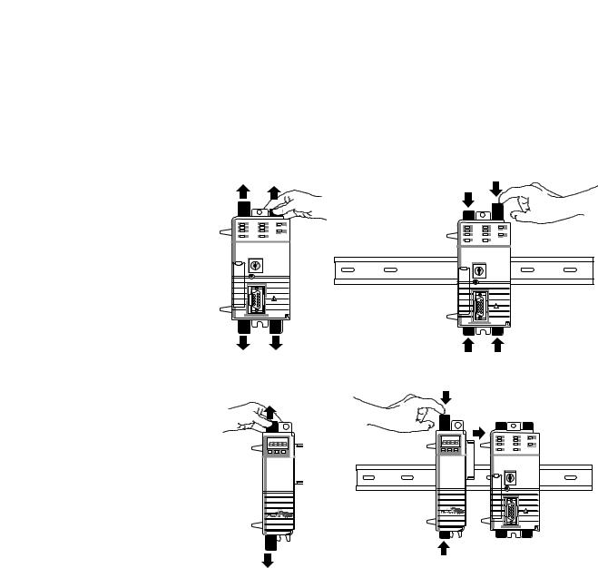
Assemble the 1768 CompactLogix System
1768-L43 Controller, 1768-L45 Controller, 1768-PA3 Power Supply, 1768-ENBT, 1768-M04SE, 1769-SDN, 1769 Local I/O Modules, 1769-ECR End Cap Terminator
1.Mount the 1768-L43 or 1768-L45 controller on the DIN rail.
a.Pull locking tabs out.
b.Slide controller into position and push locking tabs in.
2.If you have an EtherNet/IP module:
a.locate the Ethernet (MAC) address on the side of module and record address in Appendix A.
b.pull locking tabs out.
c.align module to the left of controller on DIN rail and slide the mating connector into the 1768-L43 or 1768-L45 controller.
d.push locking tabs in.
a
b
b
d
c |
Publication IASIMP-QS003B-EN-P - October 2009 |
25 |
Chapter 1 Prepare the CompactLogix Hardware
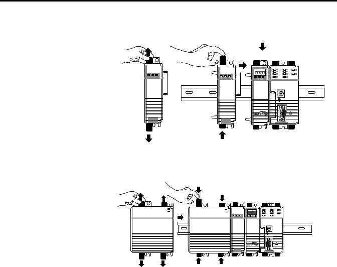
3.Mount the SERCOS 1768-M04SE module.
a.Pull locking tabs out.
b.Align SERCOS module to the left of EtherNet/IP module or controller and slide into place.
c.Push locking tabs in.
4.Mount the power supply on the DIN rail.
a.Pull locking tabs out.
b.Align supply to the left of the SERCOS module and slide into place.
c.Push locking tabs in.
5.If you have a 1769-SDN DeviceNet module, locate the series letter and firmware revision on the side of the module and record in Appendix A.
a |
c |
|
b |
a |
c |
b |
26 |
Publication IASIMP-QS003B-EN-P - October 2009 |
Prepare the CompactLogix Hardware |
Chapter 1 |
|
|
6.Mount the 1769-SDN and 1769 I/O modules to the right of the controller on DIN rail.
In this quick start, the 1769-SDN module is directly to the right of the controller in slot 1.
a.Pull locking tabs out.
b.Slide module along tongue-and-groove slots on the side of the controller or modules.
c.Push locking tabs in.
d.Slide white locking tab to the left.
A maximum of three modules can be mounted between the 1769-SDN and the power supply.
b
c d 
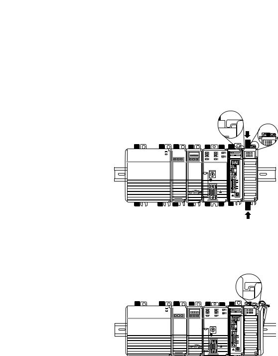
7.Mount the 1769-ECR end cap terminator.
a.Pull locking tab to the right.
b.Slide end cap on rail.
c.Pull locking tab to the left.
b |
c |
a |
Publication IASIMP-QS003B-EN-P - October 2009 |
27 |
Chapter 1 Prepare the CompactLogix Hardware
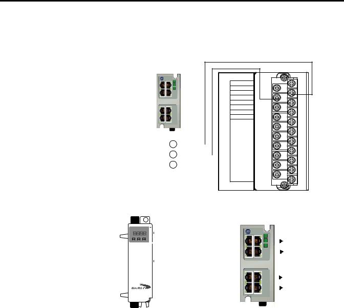
Make EtherNet/IP Network Connection
1.Mount the Ethernet switch to the DIN rail.
2.Connect the Ethernet switch power terminals to the I/O power terminals on the front of the line interface module.
|
Line Interface Module |
||
|
I/O Power |
||
|
IOL |
|
|
1 |
IO_PWR1 |
|
|
2 |
IO_COM1 |
3 |
|
3 |
IO_PWR1 |
||
4 |
|||
4 |
IO_COM1 |
||
5 |
IO_PWR1 |
|
|
6 |
IO_COM1 |
|
|
7 |
COIL_E1 |
|
|
8 |
COIL_E2 |
|
|
|
|
|
|
|
|
|
|
|
|
|
|
|
9 |
ALRM_M |
10 |
|
SHIELD |
||||||||||||
|
|
|
|
|
|
|
|
|
|
|
|
|
11 |
ALRM_B |
24VDC (+) |
|
|
12 |
|
ALRM_COM |
|||||||||
|
|
|
|
|
|
|
|
|
|
|
|
13 |
CONSTAT_11 |
|
DC NEUT (-) |
|
|
|
|
|
|
|
|
|
|
14 |
|
CONSTAT_12 |
|
|
|
|
|
|
|
|
|
|
|
|
|
15 |
CONSTAT_21 |
|
CHS GND |
|
|
|
|
|
|
|
|
|
|
16 |
|
CONSTAT_22 |
|
|
|
|
|
|
|
18 |
17 |
CONSTAT_31 |
||||||
|
|
|
|
|
|
|
||||||||
|
|
|
|
|
|
|
|
CONSTAT_32 |
||||||
|
|
|
|
|
|
|
|
|
|
|
|
|
19 |
CONSTAT_53 |
|
|
|
|
|
|
|
|
|
|
|
|
|
||
|
|
|
|
|
20 |
|
CONSTAT_54 |
|||||||
|
|
|
|
|||||||||||
|
|
|
|
|
|
|
|
|
|
|
|
|
21 |
SHIELD |
3.Connect a CAT5 Ethernet cable between the Ethernet port on the bottom of 1768-ENBT module and the Ethernet switch.
4.Do not turn on incoming power.
Front View
|
|
|
|
|
|
|
|
|
|
|
|
|
|
|
|
|
|
|
|
|
|
|
|
|
Computer |
|
|
|
|
|
|
|
|
|
|
|
|
|
|
|
|
|
|
|
|
|
|
|
|
|
|
|
|
|
|
|
|
|
|
|
|
|
8 |
|
|
|
|
|
|
|
|
POINT I/O |
|||||
|
|
|
|
|
|
|
|
||||||||||||||||||
|
|
|
|
|
|
|
|
|
|
|
|
|
|
|
|
|
|
|
|
|
|
|
|
|
connection |
|
|
|
|
|
|
|
|
|
|
|
|
|
|
|
|
|
|
|
|
|
|
||||
|
|
|
|
|
|
|
|
|
|
|
|
|
|
|
|
|
|
|
|
|
|
|
|
|
|
|
|
|
|
|
|
|
|
|
|
|
|
|
|
|
|
1 |
|
|
|
|
|
|
|
|
PowerFlex 70 |
|
|
|
|
|
|
|
|
|
|
|
|
|
|
|
|
|
|
|
|
|
|
|
|
||
|
|
|
|
|
|
|
|
|
|
|
|
|
|
|
|
|
|
|
|
|
|
|
|
||
|
|
|
|
|
|
|
|
|
|
|
|
|
|
|
|
|
|
|
|
|
|
|
|
|
connection |
|
|
|
|
|
|
|
|
|
|
|
|
|
|
|
|
|
|
|
|
|
|
|
|
|
PanelView Plus |
|
|
|
|
|
|
|
|
|
|
|
|
|
|
|
|
|
|
|
|
|
|
|
|
|
|
|
|
|
|
|
|
|
|
|
|
|
|
|
|
|
|
|
|
|
|
|
|
|
|
||
|
|
|
|
|
|
|
|
|
|
|
|
|
|
|
|
|
|
|
|
|
|
|
|
|
|
|
|
|
|
|
|
|
|
|
|
|
|
|
|
|
|
|
|
|
|
|
|
|
|
|
|
|
|
|
|
|
|
|
|
|
|
|
|
|
Ethernet CAT5 Cable |
|
|
|
|
|
connection |
||||||
|
|
|
|
|
|
|
|
|
|
|
|
|
|
|
|
|
|
||||||||
|
|
|
|
|
|
|
|
|
|
|
|
|
|
|
|
|
|
|
|||||||
|
|
|
|
|
|
|
|
|
|
|
|
|
|
|
|||||||||||
28 |
Publication IASIMP-QS003B-EN-P - October 2009 |

Prepare the CompactLogix Hardware |
Chapter 1 |
|
|
Make DeviceNet Network Connections
1.Attach and lock the 1606-XLDNET8 DeviceNet power supply to a DIN rail by pressing the tab at the top of the supply.
AC 120V
AC 240V
 Input
Input
ACN100L-120/200-240V
Isolate power before discon necting
DC ok
1606- |
|
|
|
|
||
|
|
|
|
|||
XL |
|
|
||||
|
|
|||||
POWER |
|
|
|
|||
|
|
SUPPLY |
|
|
||
Output |
|
|
|
|
|
|
|
|
|
|
|
||
|
|
|
|
|
||
|
|
|
|
|
||
|
|
|
|
|
||
200W |
Limited |
|
|
|
|
|
DC |
Power |
|
|
|||
24V / 8A |
|
|
||||
+ |
– |
|
|
|
|
|
|
|
DC ok |
|
|
||
Publication IASIMP-QS003B-EN-P - October 2009 |
29 |
Chapter 1 Prepare the CompactLogix Hardware
2. |
Assemble the DeviceNet |
|||
|
network cable system |
|||
|
using the KwikLink flat |
|||
|
cable, terminators, and |
|||
|
sealed micro connectors |
|||
|
for each device. |
|||
|
See instructions included |
|||
|
with devices. |
|||
3. Wire a KwikLink QD |
||||
|
Micro Cordset to the |
|||
|
1769-SDN connector. |
|||
|
|
|
|
|
|
|
Connect |
To |
|
|
|
Red |
V+ |
|
|
|
White |
CAN High |
|
|
|
|
|
|
|
|
Bare |
Shield |
|
|
|
|
|
|
|
|
Blue |
CAN Low |
|
|
|
|
|
|
|
|
Black |
V- |
|
|
|
|
|
|
4. Connect the QD Micro |
||||
|
Cordset to a KwikLink |
|||
|
sealed microconnector on |
|||
|
the network. |
|||
5. |
Connect the DeviceNet |
|||
|
KwikLink power tap to |
|||
|
the power supply Output |
|||
|
connector. |
|
|
|
|
|
|
|
|
|
|
Connect |
To |
|
|
|
Red |
+ |
|
|
|
White |
Not Used |
|
|
|
|
|
|
|
|
Shield |
Not Used |
|
|
|
|
|
|
|
|
Blue |
Not Used |
|
|
|
|
|
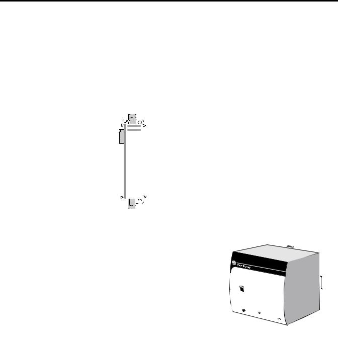
|
|
|
Black |
— |
|
|
|
|
|
|
6. |
Connect the DeviceNet |
|||
|
power tap to the |
|||
|
DeviceNet network. |
|||
|
|
|
Distributed |
KwikLink Sealed |
|||
KwikLink Sealed |
POINT I/O |
||||||
Terminator |
Connection with |
Terminator |
|||||
|
|
|
1734-ADN Adapter |
|
|
|
|
|
|
|
|
|
|
|
|
|
|
|
|
|
|
|
|
|
|
|
|
|
|
|
|
|
|
|
|
|
|
|
|
|
|
KwikLink Sealed |
|
|
|||||||||||||||
|
|
PowerFlex 70 Drive |
|||||||||||||||||
|
|
Micro Connector |
with |
||||||||||||||||
|
|
|
|
|
|
|
|
|
|
|
|
|
|
|
|
|
|
20-COMM-D |
|
|
|
|
|
|
|
|
|
|
|
|
|
|
|
|
|
|
|
|
|
|
|
|
|
|
|
|
|
|
|
|
|
|
|
|
|
|
|
|
|
|
|
|
|
|
|
|
|
|
|
|
|
|
|
|
|
|
|
|
|
|
|
|
|
|
|
|
|
|
|
|
|
|
|
|
|
|
|
|
|
|
|
|
|
|
|
|
|
|
|
|
|
|
|
|
|
|
|
|
|
|
|
|
|
|
|
|
|
|
|
|
|
|
|
|
|
|
|
|
|
|
|
|
|
|
|
|
|
|
|
|
|
|
|
|
|
|
|
|
|
|
|
|
|
|
|
|
|
|
|
|
|
|
|
|
|
|
|
|
|
|
|
|
|
|
|
|
|
|
|
|
|
|
|
|
|
|
|
|
|
|
|
|
|
|
|
|
|
|
|
|
|
|
|
|
|
|
|
|
|
|
|
|
|
|
|
|
|
|
|
|
|
|
|
|
|
|
|
|
|
|
|
|
|
|
|
|
|
|
|
|
|
|
|
|
|
|
|
|
|
|
|
|
|
|
|
|
|
|
|
|
|
|
|
|
|
|
|
|
|
|
|
|
|
|
|
|
|
|
|
|
|
|
|
|
|
|
|
|
|
|
|
|
|
|
|
|
|
|
|
|
|
|
|
|
|
|
|
|
|
|
|
|
|
|
|
|
|
|
|
|
|
|
|
|
|
|
|
|
|
|
|
|
|
|
|
|
|
|
|
|
|
|
|
|
|
|
|
|
|
|
|
|
|
|
|
|
|
|
|
|
|
|
|
|
|
|
|
|
|
|
|
|
|
|
|
|
|
|
|
|
|
|
|
|
|
|
|
|
|
|
|
|
|
|
|
|
|
|
|
|
|
|
|
|
|
|
|
|
|
|
|
|
|
|
|
|
|
|
|
|
|
|
|
|
|
|
|
|
|
1606-XLDNET8
DeviceNet Power Supply
|
|
|
|
|
|
|
|
|
|
|
1606- |
||||
|
|
|
|
|
|
|
|
|
|
|
POWER |
SUPPLYXL |
|||
|
AC |
|
|
|
|
|
|
|
|
|
|
|
|
||
|
|
|
120V |
|
|
|
|
|
|
|
|
|
|
|
|
|
AC |
|
|
|
|
|
|
|
|
|
|
|
|
||
|
|
|
240V |
|
|
|
|
|
|
|
|
|
|
|
|
|
Input |
|
|
|
|
0V |
|
|
|
|
|
|
|||
|
|
|
|
|
|
|
|
|
|
|
|||||
|
|
|
|
|
|
|
|
|
|
|
|||||
|
AC |
100-12 |
0/20 |
0-24 |
|
Outputimited |
|
||||||||
|
|
N |
L |
|
|
|
|
|
|
Power |
|||||
|
Iso |
|
|
|
|
|
DC |
|
200W |
L |
|
|
|||
|
late p |
ower b |
|
|
|
ok |
|
|
|||||||
|
|
|
|
efore d |
isconnecting |
|
DC |
24V |
/ 8A |
|
|||||
|
|
|
|
|
|
|
|
|
+ |
|
|
||||
|
|
|
|
|
|
|
|
|
– |
|
|
||||
|
|
|
|
|
|
|
|
|
|
|
|
|
|||
|
|
|
|
|
|
|
|
|
|
|
|
|
k |
||
|
|
|
|
|
|
|
|
|
|
|
|
|
|
|
|
|
|
|
|
|
|
|
|
|
|
|
|
|
|
DC o |
|
|
|
|
|
|
|
|
|
|
|
|
|
|
|
|
|
|
|
|
|
|
|
|
|
|
|
|
|
|
|
|
|
30 |
Publication IASIMP-QS003B-EN-P - October 2009 |
Loading...