


 Loading...
User Manual
MicroLogix 1400 Programmable Controllers
Bulletin 1766 Controllers and 1762 Expansion I/O

Important User Information
Solid-state equipment has operational characteristics differing from those of electromechanical equipment. Safety Guidelines for the Application, Installation and Maintenance of Solid State Controls (publication SGI-1.1 available from your local Rockwell Automation sales office or online at http://www.rockwellautomation.com/literature/) describes some important differences between solid-state equipment and hard-wired electromechanical devices. Because of this difference, and also because of the wide variety of uses for solid-state equipment, all persons responsible for applying this equipment must satisfy themselves that each intended application of this equipment is acceptable.
In no event will Rockwell Automation, Inc. be responsible or liable for indirect or consequential damages resulting from the use or application of this equipment.
The examples and diagrams in this manual are included solely for illustrative purposes. Because of the many variables and requirements associated with any particular installation, Rockwell Automation, Inc. cannot assume responsibility or liability for actual use based on the examples and diagrams.
No patent liability is assumed by Rockwell Automation, Inc. with respect to use of information, circuits, equipment, or software described in this manual.
Reproduction of the contents of this manual, in whole or in part, without written permission of Rockwell Automation, Inc., is prohibited.
Throughout this manual, when necessary, we use notes to make you aware of safety considerations.
WARNING: Identifies information about practices or circumstances that can cause an explosion in a hazardous environment, which may lead to personal injury or death, property damage, or economic loss.
ATTENTION: Identifies information about practices or circumstances that can lead to personal injury or death, property damage, or economic loss. Attentions help you identify a hazard, avoid a hazard, and recognize the consequence
SHOCK HAZARD: Labels may be on or inside the equipment, for example, a drive or motor, to alert people that dangerous voltage may be present.
BURN HAZARD: Labels may be on or inside the equipment, for example, a drive or motor, to alert people that surfaces may reach dangerous temperatures.
IMPORTANT Identifies information that is critical for successful application and understanding of the product.
Allen-Bradley, Rockwell Automation, MicroLogix, RSLinx, RSLogix 500 and TechConnect are trademarks of Rockwell Automation, Inc.
Trademarks not belonging to Rockwell Automation are property of their respective companies.

Summary of Changes
To help you find new and updated information in this release of the manual, we have included change bars as shown to the right of this paragraph.
The table below lists the sections that document new features and additional or updated information about existing features.
Summary of Changes
Topic |
Page |
|
|
Viewing and changing of protocol configuration through LCD |
59 |
|
|
MicroLogix 1400 LCD Menu Structure Tree updated with Protocol Configuration |
60 |
|
|
Protocol Configuration step-by-step guide |
116 |
|
|
Firmware Revision History Features are added to the controllers through firmware upgrades. See the latest release notes, 1766-RN001, to be sure that your controller’s firmware is at the
level you need. Firmware upgrades are not required, except to allow you access to the new features. You can only upgrade firmware within the same series of controller.
Rockwell Automation Publication 1766-UM001H-EN-P - May 2014 |
iii |

Summary of Changes
Notes:
iv |
Rockwell Automation Publication 1766-UM001H-EN-P - May 2014 |

|
Table of Contents |
|
Summary of Changes |
Firmware Revision History. . . . . . . . . . . . . . . . . . . . . . . . . . . . . . . . . . . . . . . . . |
iii |
|
Preface |
|
|
Who Should Use this Manual . . . . . . . . . . . . . . . . . . . . . . . . . . . . . . . . . . . . . |
17 |
|
Purpose of this Manual . . . . . . . . . . . . . . . . . . . . . . . . . . . . . . . . . . . . . . . . . . . |
17 |
|
Related Documentation. . . . . . . . . . . . . . . . . . . . . . . . . . . . . . . . . . . . . . . |
18 |
|
Common Techniques Used in this Manual. . . . . . . . . . . . . . . . . . . . . . . . . |
18 |
|
Chapter 1 |
|
Hardware Overview |
Hardware Features . . . . . . . . . . . . . . . . . . . . . . . . . . . . . . . . . . . . . . . . . . . . . . . . |
. 1 |
|
Component Descriptions . . . . . . . . . . . . . . . . . . . . . . . . . . . . . . . . . . . . . . . . . . |
. 2 |
|
MicroLogix 1400 Memory Module and Built-in Real-Time Clock . |
. 2 |
|
1762 Expansion I/O . . . . . . . . . . . . . . . . . . . . . . . . . . . . . . . . . . . . . . . . . . . |
. 3 |
|
Communication Cables . . . . . . . . . . . . . . . . . . . . . . . . . . . . . . . . . . . . . . . . . . . |
. 4 |
|
Programming . . . . . . . . . . . . . . . . . . . . . . . . . . . . . . . . . . . . . . . . . . . . . . . . . . . . . |
. 5 |
|
Communication Options . . . . . . . . . . . . . . . . . . . . . . . . . . . . . . . . . . . . . . . . . . |
. 5 |
|
Chapter 2 |
|
Install Your Controller |
Agency Certifications. . . . . . . . . . . . . . . . . . . . . . . . . . . . . . . . . . . . . . . . . . . . . . |
. 7 |
|
Compliance to European Union Directives. . . . . . . . . . . . . . . . . . . . . . . . . . |
. 7 |
|
EMC Directive. . . . . . . . . . . . . . . . . . . . . . . . . . . . . . . . . . . . . . . . . . . . . . . . |
. 7 |
|
Low Voltage Directive . . . . . . . . . . . . . . . . . . . . . . . . . . . . . . . . . . . . . . . . . |
. 8 |
|
Installation Considerations . . . . . . . . . . . . . . . . . . . . . . . . . . . . . . . . . . . . . . . . |
. 8 |
|
Safety Considerations . . . . . . . . . . . . . . . . . . . . . . . . . . . . . . . . . . . . . . . . . . . . . |
. 9 |
|
Hazardous Location Considerations . . . . . . . . . . . . . . . . . . . . . . . . . . . . |
. 9 |
|
Disconnecting Main Power. . . . . . . . . . . . . . . . . . . . . . . . . . . . . . . . . . . . |
10 |
|
Safety Circuits . . . . . . . . . . . . . . . . . . . . . . . . . . . . . . . . . . . . . . . . . . . . . . . |
10 |
|
Power Distribution . . . . . . . . . . . . . . . . . . . . . . . . . . . . . . . . . . . . . . . . . . . |
10 |
|
Periodic Tests of Master Control Relay Circuit . . . . . . . . . . . . . . . . . |
11 |
|
Power Considerations . . . . . . . . . . . . . . . . . . . . . . . . . . . . . . . . . . . . . . . . . . . . |
11 |
|
Isolation Transformers. . . . . . . . . . . . . . . . . . . . . . . . . . . . . . . . . . . . . . . . |
11 |
|
Power Supply Inrush. . . . . . . . . . . . . . . . . . . . . . . . . . . . . . . . . . . . . . . . . . |
11 |
|
Loss of Power Source . . . . . . . . . . . . . . . . . . . . . . . . . . . . . . . . . . . . . . . . . |
12 |
|
Input States on Power Down . . . . . . . . . . . . . . . . . . . . . . . . . . . . . . . . . . |
12 |
|
Other Types of Line Conditions . . . . . . . . . . . . . . . . . . . . . . . . . . . . . . . |
12 |
|
Preventing Excessive Heat . . . . . . . . . . . . . . . . . . . . . . . . . . . . . . . . . . . . . . . . |
12 |
|
Master Control Relay. . . . . . . . . . . . . . . . . . . . . . . . . . . . . . . . . . . . . . . . . . . . . |
13 |
|
Using Emergency-Stop Switches . . . . . . . . . . . . . . . . . . . . . . . . . . . . . . . |
14 |
|
Schematic (Using IEC Symbols) . . . . . . . . . . . . . . . . . . . . . . . . . . . . . . . |
15 |
|
Schematic (Using ANSI/CSA Symbols). . . . . . . . . . . . . . . . . . . . . . . . |
16 |
|
Installing a Memory Module . . . . . . . . . . . . . . . . . . . . . . . . . . . . . . . . . . . . . . |
16 |
|
Using the Battery . . . . . . . . . . . . . . . . . . . . . . . . . . . . . . . . . . . . . . . . . . . . . . . . |
17 |
|
Connecting the Battery Wire Connector . . . . . . . . . . . . . . . . . . . . . . . |
19 |
|
Controller Mounting Dimensions . . . . . . . . . . . . . . . . . . . . . . . . . . . . . . . . . |
20 |
|
Controller and Expansion I/O Spacing . . . . . . . . . . . . . . . . . . . . . . . . . . . . |
20 |
|
Mounting the Controller . . . . . . . . . . . . . . . . . . . . . . . . . . . . . . . . . . . . . . . . . |
20 |
Rockwell Automation Publication 1766-UM001H-EN-E - May 2014 |
v |

Table of Contents |
|
|
|
DIN Rail Mounting. . . . . . . . . . . . . . . . . . . . . . . . . . . . . . . . . . . . . . . . . . . |
22 |
|
Panel Mounting . . . . . . . . . . . . . . . . . . . . . . . . . . . . . . . . . . . . . . . . . . . . . . |
23 |
|
1762 Expansion I/O Dimensions . . . . . . . . . . . . . . . . . . . . . . . . . . . . . . . . . . |
24 |
|
Mounting 1762 Expansion I/O. . . . . . . . . . . . . . . . . . . . . . . . . . . . . . . . . . . . |
24 |
|
DIN Rail Mounting. . . . . . . . . . . . . . . . . . . . . . . . . . . . . . . . . . . . . . . . . . . |
24 |
|
Panel Mounting . . . . . . . . . . . . . . . . . . . . . . . . . . . . . . . . . . . . . . . . . . . . . . |
25 |
|
Connecting Expansion I/O . . . . . . . . . . . . . . . . . . . . . . . . . . . . . . . . . . . . . . . |
26 |
|
Chapter 3 |
|
Wire Your Controller |
Wiring Requirements . . . . . . . . . . . . . . . . . . . . . . . . . . . . . . . . . . . . . . . . . . . . |
27 |
|
Wiring Recommendation . . . . . . . . . . . . . . . . . . . . . . . . . . . . . . . . . . . . . |
27 |
|
Wire without Spade Lugs. . . . . . . . . . . . . . . . . . . . . . . . . . . . . . . . . . . . . . |
28 |
|
Wire with Spade Lugs . . . . . . . . . . . . . . . . . . . . . . . . . . . . . . . . . . . . . . . . . |
28 |
|
Using Surge Suppressors . . . . . . . . . . . . . . . . . . . . . . . . . . . . . . . . . . . . . . . . . . |
29 |
|
Recommended Surge Suppressors . . . . . . . . . . . . . . . . . . . . . . . . . . . . . . |
30 |
|
Grounding the Controller. . . . . . . . . . . . . . . . . . . . . . . . . . . . . . . . . . . . . . . . . |
31 |
|
Wiring Diagrams . . . . . . . . . . . . . . . . . . . . . . . . . . . . . . . . . . . . . . . . . . . . . . . . . |
32 |
|
Terminal Block Layouts . . . . . . . . . . . . . . . . . . . . . . . . . . . . . . . . . . . . . . . |
33 |
|
Sinking and Sourcing Wiring Diagrams . . . . . . . . . . . . . . . . . . . . . . . . . . . . |
36 |
|
1766-L32BWA, 1766-L32AWA, 1766-L32BXB, 1766-L32BWAA, |
|
|
1766-L32AWAA, 1766-L32BXBA Wiring Diagrams . . . . . . . . . . . |
36 |
|
Controller I/O Wiring. . . . . . . . . . . . . . . . . . . . . . . . . . . . . . . . . . . . . . . . . . . . |
38 |
|
Minimizing Electrical Noise . . . . . . . . . . . . . . . . . . . . . . . . . . . . . . . . . . . |
38 |
|
Wiring Your Analog Channels . . . . . . . . . . . . . . . . . . . . . . . . . . . . . . . . . . . . |
39 |
|
Analog Channel Wiring Guidelines . . . . . . . . . . . . . . . . . . . . . . . . . . . . |
40 |
|
Minimizing Electrical Noise on Analog Channels . . . . . . . . . . . . . . . |
41 |
|
Grounding Your Analog Cable . . . . . . . . . . . . . . . . . . . . . . . . . . . . . . . . |
42 |
|
Expansion I/O Wiring . . . . . . . . . . . . . . . . . . . . . . . . . . . . . . . . . . . . . . . . . . . . |
42 |
|
Digital Wiring Diagrams . . . . . . . . . . . . . . . . . . . . . . . . . . . . . . . . . . . . . . |
42 |
|
Analog Wiring . . . . . . . . . . . . . . . . . . . . . . . . . . . . . . . . . . . . . . . . . . . . . . . |
50 |
|
Chapter 4 |
|
Communication Connections |
Supported Communication Protocols. . . . . . . . . . . . . . . . . . . . . . . . . . . . . . |
59 |
|
Default Communication Configuration. . . . . . . . . . . . . . . . . . . . . . . . . . . . |
60 |
|
Using the Communications Toggle Functionality . . . . . . . . . . . . . . . . . . . |
60 |
|
Changing Communication Configuration . . . . . . . . . . . . . . . . . . . . . . |
61 |
|
Connecting to the RS-232 Port. . . . . . . . . . . . . . . . . . . . . . . . . . . . . . . . . . . . |
63 |
|
Making a DF1 Point-to-Point Connection. . . . . . . . . . . . . . . . . . . . . . |
64 |
|
Using a Modem . . . . . . . . . . . . . . . . . . . . . . . . . . . . . . . . . . . . . . . . . . . . . . |
65 |
|
Connecting to a DF1 Half-Duplex Network . . . . . . . . . . . . . . . . . . . . |
68 |
|
Connecting to a RS-485 Network. . . . . . . . . . . . . . . . . . . . . . . . . . . . . . . . . . |
70 |
|
DH-485 Configuration Parameters . . . . . . . . . . . . . . . . . . . . . . . . . . . . |
71 |
|
Recommended Tools . . . . . . . . . . . . . . . . . . . . . . . . . . . . . . . . . . . . . . . . . |
73 |
|
DH-485 Communication Cable . . . . . . . . . . . . . . . . . . . . . . . . . . . . . . . |
73 |
vi |
Rockwell Automation Publication 1766-UM001H-EN-E - May 2014 |

|
|
Table of Contents |
|
|
|
|
Connecting the Communication Cable to the DH-485 Connector. . |
|
|
74 |
|
|
Grounding and Terminating the DH-485 Network . . . |
. . . . . . . . . . 75 |
|
Connecting the AIC+ . . . . . . . . . . . . . . . . . . . . . . . . . . . . . . . . . . . |
. . . . . . . . . 76 |
|
Cable Selection Guide . . . . . . . . . . . . . . . . . . . . . . . . . . . . . . . |
. . . . . . . . . 77 |
|
Recommended User-Supplied Components . . . . . . . . . . . |
. . . . . . . . . 80 |
|
Safety Considerations. . . . . . . . . . . . . . . . . . . . . . . . . . . . . . . . |
. . . . . . . . . 81 |
|
Install and Attach the AIC+. . . . . . . . . . . . . . . . . . . . . . . . . . |
. . . . . . . . . 81 |
|
Powering the AIC+. . . . . . . . . . . . . . . . . . . . . . . . . . . . . . . . . . |
. . . . . . . . . 82 |
|
Connecting to DeviceNet. . . . . . . . . . . . . . . . . . . . . . . . . . . . . . . . |
. . . . . . . . . 83 |
|
Cable Selection Guide . . . . . . . . . . . . . . . . . . . . . . . . . . . . . . . |
. . . . . . . . . 83 |
|
Connecting to Ethernet . . . . . . . . . . . . . . . . . . . . . . . . . . . . . . . . . |
. . . . . . . . . 84 |
|
Ethernet Connections . . . . . . . . . . . . . . . . . . . . . . . . . . . . . . . |
. . . . . . . . . 85 |
|
Chapter 5 |
|
Using the LCD |
Operating Principles. . . . . . . . . . . . . . . . . . . . . . . . . . . . . . . . . . . . . |
. . . . . . . . . 88 |
|
Main Menu and Default Screen. . . . . . . . . . . . . . . . . . . . . . . |
. . . . . . . . . 91 |
|
Operating Buttons. . . . . . . . . . . . . . . . . . . . . . . . . . . . . . . . . . . |
. . . . . . . . . 93 |
|
Using Menus to Choose Values . . . . . . . . . . . . . . . . . . . . . . . |
. . . . . . . . . 93 |
|
Selecting Between Menu Items . . . . . . . . . . . . . . . . . . . . . . . |
. . . . . . . . . 93 |
|
Cursor Display . . . . . . . . . . . . . . . . . . . . . . . . . . . . . . . . . . . . . . |
. . . . . . . . . 94 |
|
Setting Values . . . . . . . . . . . . . . . . . . . . . . . . . . . . . . . . . . . . . . . |
. . . . . . . . . 95 |
|
I/O Status . . . . . . . . . . . . . . . . . . . . . . . . . . . . . . . . . . . . . . . . . . . . . . |
. . . . . . . . . 95 |
|
Viewing I/O Status . . . . . . . . . . . . . . . . . . . . . . . . . . . . . . . . . . |
. . . . . . . . . 96 |
|
Monitor User Defined Target Files . . . . . . . . . . . . . . . . . . . . . . . |
. . . . . . . . . 97 |
|
Target User Defined File Number (TUF) . . . . . . . . . . . . . |
. . . . . . . . . 97 |
|
Monitoring a Bit File . . . . . . . . . . . . . . . . . . . . . . . . . . . . . . . . |
. . . . . . . . . 98 |
|
Monitoring Integer Files . . . . . . . . . . . . . . . . . . . . . . . . . . . . . |
. . . . . . . . 102 |
|
Monitoring Double Integer files . . . . . . . . . . . . . . . . . . . . . . |
. . . . . . . . 107 |
|
Monitor Floating point Files . . . . . . . . . . . . . . . . . . . . . . . . . |
. . . . . . . . 113 |
|
Monitor System Status Files . . . . . . . . . . . . . . . . . . . . . . . . . . |
. . . . . . . . 113 |
|
Using the Mode Switch . . . . . . . . . . . . . . . . . . . . . . . . . . . . . . . . . . |
. . . . . . . . 114 |
|
Controller Modes . . . . . . . . . . . . . . . . . . . . . . . . . . . . . . . . . . . |
. . . . . . . . 115 |
|
Changing Mode Switch Position. . . . . . . . . . . . . . . . . . . . . . |
. . . . . . . . 115 |
|
Using a User Defined LCD Screen . . . . . . . . . . . . . . . . . . . . . . . |
. . . . . . . . 117 |
|
User Defined LCD Screen . . . . . . . . . . . . . . . . . . . . . . . . . . . |
. . . . . . . . 118 |
|
Configuring Advanced Settings . . . . . . . . . . . . . . . . . . . . . . . . . . |
. . . . . . . . 119 |
|
Changing Key In Mode . . . . . . . . . . . . . . . . . . . . . . . . . . . . . . . . . . |
. . . . . . . . 120 |
|
Key In Modes . . . . . . . . . . . . . . . . . . . . . . . . . . . . . . . . . . . . . . . |
. . . . . . . . 120 |
|
Changing Key In Mode . . . . . . . . . . . . . . . . . . . . . . . . . . . . . . |
. . . . . . . . 120 |
|
Using Communications Toggle Functionality . . . . . . . . . . . . . |
. . . . . . . . 122 |
|
Ethernet Network Configuration. . . . . . . . . . . . . . . . . . . . . . . . . |
. . . . . . . . 122 |
|
Viewing Ethernet Status . . . . . . . . . . . . . . . . . . . . . . . . . . . . . |
. . . . . . . . 122 |
|
Configuring the IP Address . . . . . . . . . . . . . . . . . . . . . . . . . . |
. . . . . . . . 124 |
|
Configuring the Ethernet Port. . . . . . . . . . . . . . . . . . . . . . . . |
. . . . . . . . 128 |
Rockwell Automation Publication 1766-UM001H-EN-E - May 2014 |
vii |

Table of Contents
Using Real-Time Clock and
Memory Modules
Configuring Ethernet Protocol Setup. . . . . . . . . . . . . . . . . . . . . . . . . . 130
Using Trim Pots. . . . . . . . . . . . . . . . . . . . . . . . . . . . . . . . . . . . . . . . . . . . . . . . . 133
Trim Pot Operation . . . . . . . . . . . . . . . . . . . . . . . . . . . . . . . . . . . . . . . . . 133 Changing Data Value of a Trim Pot . . . . . . . . . . . . . . . . . . . . . . . . . . . 134
Trim Pot Configuration in LCD Function File . . . . . . . . . . . . . . . . 135
Error Conditions . . . . . . . . . . . . . . . . . . . . . . . . . . . . . . . . . . . . . . . . . . . . 135 Viewing System Information . . . . . . . . . . . . . . . . . . . . . . . . . . . . . . . . . . . . . 136
Viewing Fault Code . . . . . . . . . . . . . . . . . . . . . . . . . . . . . . . . . . . . . . . . . . . . . 137
Saving/Loading Communication EEPROM . . . . . . . . . . . . . . . . . . . . . . . 138 Saving Communication EEPROM . . . . . . . . . . . . . . . . . . . . . . . . . . . . 138
Loading communication EEPROM . . . . . . . . . . . . . . . . . . . . . . . . . . . 141
LCD setup. . . . . . . . . . . . . . . . . . . . . . . . . . . . . . . . . . . . . . . . . . . . . . . . . . . . . . 141 Configuring contrast value . . . . . . . . . . . . . . . . . . . . . . . . . . . . . . . . . . . 142
Configuring the backlight . . . . . . . . . . . . . . . . . . . . . . . . . . . . . . . . . . . . 143 Protocol Configuration . . . . . . . . . . . . . . . . . . . . . . . . . . . . . . . . . . . . . . . . . . 144 Modbus RTU Slave . . . . . . . . . . . . . . . . . . . . . . . . . . . . . . . . . . . . . . . . . . 144
Chapter 6
Real-Time Clock Operation. . . . . . . . . . . . . . . . . . . . . . . . . . . . . . . . . . . . . . 147
Operation at Power-up and Entering a Run or Test Mode. . . . . . . 147
Writing Data to the Real-Time Clock . . . . . . . . . . . . . . . . . . . . . . . . . 147
RTC Battery Operation . . . . . . . . . . . . . . . . . . . . . . . . . . . . . . . . . . . . . . 148
Memory Module Operation . . . . . . . . . . . . . . . . . . . . . . . . . . . . . . . . . . . . . . 148
User Program , User Data, Datalog and Recipe Back-up. . . . . . . . . 149
Program Compare . . . . . . . . . . . . . . . . . . . . . . . . . . . . . . . . . . . . . . . . . . . 149
Data File Download Protection . . . . . . . . . . . . . . . . . . . . . . . . . . . . . . . 149
Memory Module Write Protection . . . . . . . . . . . . . . . . . . . . . . . . . . . . 149
Removal/Insertion Under Power . . . . . . . . . . . . . . . . . . . . . . . . . . . . . 150
Memory Module Information File . . . . . . . . . . . . . . . . . . . . . . . . . . . . 150
Program /Data Download . . . . . . . . . . . . . . . . . . . . . . . . . . . . . . . . . . . . 150
Program /Data Upload. . . . . . . . . . . . . . . . . . . . . . . . . . . . . . . . . . . . . . . 150
|
Chapter 7 |
|
Online Editing |
Directions and Cautions for MicroLogix 1400 Online |
|
|
Editing User . . . . . . . . . . . . . . . . . . . . . . . . . . . . . . . . . . . . . . . . . . . . . . . . . . . . |
151 |
|
A Download is Required Before Starting Online Editing . . . . . . . . |
151 |
|
Types of Online Editing . . . . . . . . . . . . . . . . . . . . . . . . . . . . . . . . . . . . . . . . . |
152 |
|
Edit Functions in Runtime Online Editing. . . . . . . . . . . . . . . . . . . . . |
153 |
|
Edit Functions in Program Online Editing . . . . . . . . . . . . . . . . . . . . . |
153 |
|
Appendix A |
|
Specifications |
Specifications for Inputs. . . . . . . . . . . . . . . . . . . . . . . . . . . . . . . . . . . . . . |
155 |
|
Specifications for Outputs in Hazardous Locations |
|
|
(Class 1, Division 2, Groups A, B, C, D) . . . . . . . . . . . . . . . . . . . . . . . |
157 |
viii |
Rockwell Automation Publication 1766-UM001H-EN-E - May 2014 |

|
Table of Contents |
|
|
Specifications for Outputs in (Non-Hazardous) Locations only |
158 |
|
Working Voltage . . . . . . . . . . . . . . . . . . . . . . . . . . . . . . . . . . . . . . . . . . |
161 |
|
Expansion I/O Specifications . . . . . . . . . . . . . . . . . . . . . . . . . . . . . . . . . . . . |
162 |
|
Digital I/O Modules. . . . . . . . . . . . . . . . . . . . . . . . . . . . . . . . . . . . . . . . . |
162 |
|
Analog Modules . . . . . . . . . . . . . . . . . . . . . . . . . . . . . . . . . . . . . . . . . . . . |
169 |
|
Appendix B |
|
Replacement Parts |
MicroLogix 1400 Replacement Kits . . . . . . . . . . . . . . . . . . . . . . . . . . . . . . |
179 |
|
Lithium Battery (1747-BA) . . . . . . . . . . . . . . . . . . . . . . . . . . . . . . . . . . . . . |
179 |
|
Installation . . . . . . . . . . . . . . . . . . . . . . . . . . . . . . . . . . . . . . . . . . . . . . . . . |
179 |
|
Battery Handling . . . . . . . . . . . . . . . . . . . . . . . . . . . . . . . . . . . . . . . . . . . . |
181 |
|
Storage . . . . . . . . . . . . . . . . . . . . . . . . . . . . . . . . . . . . . . . . . . . . . . . . . . . . . |
181 |
|
Transportation . . . . . . . . . . . . . . . . . . . . . . . . . . . . . . . . . . . . . . . . . . . . . |
181 |
|
Disposal . . . . . . . . . . . . . . . . . . . . . . . . . . . . . . . . . . . . . . . . . . . . . . . . . . . . |
183 |
|
Appendix C |
|
Troubleshooting Your System |
Understanding the Controller Status Indicators . . . . . . . . . . . . . . . . . . . |
185 |
|
Controller Status LED Indicators. . . . . . . . . . . . . . . . . . . . . . . . . . . . . |
185 |
|
Status Indicators on the LCD . . . . . . . . . . . . . . . . . . . . . . . . . . . . . . . . |
186 |
|
I/O Status Indicators on the LCD . . . . . . . . . . . . . . . . . . . . . . . . . . . . |
187 |
|
Normal Operation. . . . . . . . . . . . . . . . . . . . . . . . . . . . . . . . . . . . . . . . . . . |
187 |
|
Error Conditions . . . . . . . . . . . . . . . . . . . . . . . . . . . . . . . . . . . . . . . . . . . . |
187 |
|
Controller Error Recovery Model. . . . . . . . . . . . . . . . . . . . . . . . . . . . . . . . . |
188 |
|
Analog Expansion I/O Diagnostics and Troubleshooting . . . . . . . . . . . |
190 |
|
Module Operation and Channel Operation . . . . . . . . . . . . . . . . . . . |
190 |
|
Power-up Diagnostics. . . . . . . . . . . . . . . . . . . . . . . . . . . . . . . . . . . . . . . . |
190 |
|
Critical and Non-Critical Errors . . . . . . . . . . . . . . . . . . . . . . . . . . . . . . |
191 |
|
Module Error Definition Table . . . . . . . . . . . . . . . . . . . . . . . . . . . . . . . |
191 |
|
Error Codes. . . . . . . . . . . . . . . . . . . . . . . . . . . . . . . . . . . . . . . . . . . . . . . . . |
192 |
|
Calling Rockwell Automation for Assistance . . . . . . . . . . . . . . . . . . . . . . |
193 |
Using ControlFLASH to Upgrade Your Operating System
Appendix D
Preparing for Firmware Upgrade . . . . . . . . . . . . . . . . . . . . . . . . . . . . . . . . . 195
Install ControlFLASH Software . . . . . . . . . . . . . . . . . . . . . . . . . . . . . . 195
Prepare the Controller for Firmware Upgrade . . . . . . . . . . . . . . . . . 196 Using ControlFLASH for Firmware Upgrade . . . . . . . . . . . . . . . . . . . . . 197
ControlFLASH Error Messages . . . . . . . . . . . . . . . . . . . . . . . . . . . . . . . . . . 207
Missing or Corrupt OS state . . . . . . . . . . . . . . . . . . . . . . . . . . . . . . . . . . . . . 209 Recovering from Missing or Corrupt OS State . . . . . . . . . . . . . . . . . 210
Connecting to Networks via RS- 232/RS-485 Interface
Appendix E
RS-232 Communication Interface . . . . . . . . . . . . . . . . . . . . . . . . . . . . . . . . 211
RS-485 Communication Interface . . . . . . . . . . . . . . . . . . . . . . . . . . . . . . . . 211
DF1 Full-Duplex Protocol . . . . . . . . . . . . . . . . . . . . . . . . . . . . . . . . . . . . . . . 211
Rockwell Automation Publication 1766-UM001H-EN-E - May 2014 |
ix |

Table of Contents
MicroLogix 1400 Distributed
Network Protocol (DNP3)
DF1 Half-Duplex Protocol. . . . . . . . . . . . . . . . . . . . . . . . . . . . . . . . . . . . . . . 212
DF1 Half-Duplex Operation . . . . . . . . . . . . . . . . . . . . . . . . . . . . . . . . . 212
Considerations When Communicating as a DF1 Slave
on a Multi-drop Link . . . . . . . . . . . . . . . . . . . . . . . . . . . . . . . . . . . . . . . . 214
Using Modems with MicroLogix Programmable Controllers . . . . 214
DH-485 Communication Protocol . . . . . . . . . . . . . . . . . . . . . . . . . . . . . . . 215 DH-485 Configuration Parameters . . . . . . . . . . . . . . . . . . . . . . . . . . . 216
Devices that use the DH-485 Network . . . . . . . . . . . . . . . . . . . . . . . . 216
Important DH-485 Network Planning Considerations . . . . . . . . . 217 Example DH-485 Connections . . . . . . . . . . . . . . . . . . . . . . . . . . . . . . . 221
Modbus Communication Protocol . . . . . . . . . . . . . . . . . . . . . . . . . . . . . . . 223
ASCII . . . . . . . . . . . . . . . . . . . . . . . . . . . . . . . . . . . . . . . . . . . . . . . . . . . . . . . . . 223 Distributed Network Protocol (DNP3) . . . . . . . . . . . . . . . . . . . . . . . . . . . 223
Appendix F
Channel Configuration for DNP3 Slave. . . . . . . . . . . . . . . . . . . . . . . . . . . 225
Channel 0 and Channel 2 Link Layer Configuration. . . . . . . . . . . . 227 Channel 1 Link Layer Configuration . . . . . . . . . . . . . . . . . . . . . . . . . . 228
DNP3 Slave Application Layer Configuration . . . . . . . . . . . . . . . . . 230
Channel 0 and Channel 2 Link Layer Configuration Parameters. 232 Channel 1(Ethernet) Link Layer Configuration Parameters . . . . . 236
DNP3 Slave Application Layer Configuration Parameters. . . . . . . 241
DNP3 Slave Application Layer . . . . . . . . . . . . . . . . . . . . . . . . . . . . . . . . . . . 254 Function Codes . . . . . . . . . . . . . . . . . . . . . . . . . . . . . . . . . . . . . . . . . . . . . 254
Internal Indications . . . . . . . . . . . . . . . . . . . . . . . . . . . . . . . . . . . . . . . . . . 259
DNP3 Objects and MicroLogix 1400 Data Files . . . . . . . . . . . . . . . . . . . 260 DNP3 Data Files . . . . . . . . . . . . . . . . . . . . . . . . . . . . . . . . . . . . . . . . . . . . 264
DNP 3 Configuration Files . . . . . . . . . . . . . . . . . . . . . . . . . . . . . . . . . . . 265
DNP3 Binary Input Object. . . . . . . . . . . . . . . . . . . . . . . . . . . . . . . . . . . 269 DNP3 Binary Output Object . . . . . . . . . . . . . . . . . . . . . . . . . . . . . . . . . 271
DNP3 Double Bit Binary Input Object. . . . . . . . . . . . . . . . . . . . . . . . 274
DNP3 Counter Object. . . . . . . . . . . . . . . . . . . . . . . . . . . . . . . . . . . . . . . 276
DNP3 Frozen Counter Object. . . . . . . . . . . . . . . . . . . . . . . . . . . . . . . . 279
DNP3 Analog Input Object . . . . . . . . . . . . . . . . . . . . . . . . . . . . . . . . . . 281 DNP3 Analog Output Object . . . . . . . . . . . . . . . . . . . . . . . . . . . . . . . . 285
DNP3 BCD Object. . . . . . . . . . . . . . . . . . . . . . . . . . . . . . . . . . . . . . . . . . 287
DNP3 Data Set Object. . . . . . . . . . . . . . . . . . . . . . . . . . . . . . . . . . . . . . . 289 Object Quality Flags . . . . . . . . . . . . . . . . . . . . . . . . . . . . . . . . . . . . . . . . . 299
DNP3 Device Attribute Object. . . . . . . . . . . . . . . . . . . . . . . . . . . . . . . . . . . 303
Event Reporting. . . . . . . . . . . . . . . . . . . . . . . . . . . . . . . . . . . . . . . . . . . . . . . . . 307 Generating Events . . . . . . . . . . . . . . . . . . . . . . . . . . . . . . . . . . . . . . . . . . . 307 Control Generating Event. . . . . . . . . . . . . . . . . . . . . . . . . . . . . . . . . . . . 311
Reporting Event By Polled Response . . . . . . . . . . . . . . . . . . . . . . . . . . 312 Reporting Event By Unsolicited Response . . . . . . . . . . . . . . . . . . . . . 313 Collision Avoidance . . . . . . . . . . . . . . . . . . . . . . . . . . . . . . . . . . . . . . . . . . . . . 315
x |
Rockwell Automation Publication 1766-UM001H-EN-E - May 2014 |
Table of Contents
Connecting to Networks via Ethernet Interface
Time Synchronization . . . . . . . . . . . . . . . . . . . . . . . . . . . . . . . . . . . . . . . . . . . 316
Download a User Program via DNP3 Network . . . . . . . . . . . . . . . . . . . . 317
Default Directories and Files . . . . . . . . . . . . . . . . . . . . . . . . . . . . . . . . . 318 Generating *.IMG files using RSLogix 500/RSLogix Micro . . . . . 318
Rules for File Authentication . . . . . . . . . . . . . . . . . . . . . . . . . . . . . . . . . 320
Rules for Downloading a User Program . . . . . . . . . . . . . . . . . . . . . . . 321 Rules for Uploading a User Program . . . . . . . . . . . . . . . . . . . . . . . . . . 322
Rules for Initializing a User Program . . . . . . . . . . . . . . . . . . . . . . . . . . 324
Rules for uploading Communication Status Files. . . . . . . . . . . . . . . 324 Starting and Stopping User Programs (Mode Change) via DNP3
Network. . . . . . . . . . . . . . . . . . . . . . . . . . . . . . . . . . . . . . . . . . . . . . . . . . . . 324
Initialize User Program . . . . . . . . . . . . . . . . . . . . . . . . . . . . . . . . . . . . . . 325 Start User Program . . . . . . . . . . . . . . . . . . . . . . . . . . . . . . . . . . . . . . . . . . 325
Stop User Program . . . . . . . . . . . . . . . . . . . . . . . . . . . . . . . . . . . . . . . . . . 325 Diagnostics . . . . . . . . . . . . . . . . . . . . . . . . . . . . . . . . . . . . . . . . . . . . . . . . . . . . . 326 Diagnostics for Ethernet Channel (Channel 1). . . . . . . . . . . . . . . . . 332 Diagnostics for Secure Authentication . . . . . . . . . . . . . . . . . . . . . . . . 339 Function Codes . . . . . . . . . . . . . . . . . . . . . . . . . . . . . . . . . . . . . . . . . . . . . . . . . 341 Implementation Table. . . . . . . . . . . . . . . . . . . . . . . . . . . . . . . . . . . . . . . . . . . 344
Appendix G
MicroLogix 1400 Controllers and Ethernet Communication . . . . . . . 355
MicroLogix 1400 Performance Considerations . . . . . . . . . . . . . . . . . . . . 356 MicroLogix 1400 and PC Connections to the
Ethernet Network. . . . . . . . . . . . . . . . . . . . . . . . . . . . . . . . . . . . . . . . . . . . . . . 357
Ethernet Network Topology . . . . . . . . . . . . . . . . . . . . . . . . . . . . . . . . . 357 Connecting an Ethernet switch on the Ethernet Network. . . . . . . 357
Cables . . . . . . . . . . . . . . . . . . . . . . . . . . . . . . . . . . . . . . . . . . . . . . . . . . . . . . 358
Ethernet Connections . . . . . . . . . . . . . . . . . . . . . . . . . . . . . . . . . . . . . . . . . . . 360 Duplicate IP address Detection . . . . . . . . . . . . . . . . . . . . . . . . . . . . . . . . . . 361
Configuring the Ethernet Channel on the MicroLogix 1400 . . . . . . . . 362
Configuration Using RSLogix 500/RSLogix Micro Programming
Software. . . . . . . . . . . . . . . . . . . . . . . . . . . . . . . . . . . . . . . . . . . . . . . . . . . . . . . . 364
Configuration Via BOOTP . . . . . . . . . . . . . . . . . . . . . . . . . . . . . . . . . . . . . . 364 Using the Rockwell Automation BOOTP/DHCP Utility . . . . . . 365
Using a DHCP Server To Configure Your Processor . . . . . . . . . . . . . . . 367
Using Subnet Masks and Gateways . . . . . . . . . . . . . . . . . . . . . . . . . . . . . . . 368 Manually Configuring Channel 1 for Controllers on
Subnets . . . . . . . . . . . . . . . . . . . . . . . . . . . . . . . . . . . . . . . . . . . . . . . . . . . . . 369
MicroLogix 1400 Embedded Web Server Capability . . . . . . . . . . . . . . . 369
|
Appendix H |
|
System Loading and Heat |
System Loading Calculations . . . . . . . . . . . . . . . . . . . . . . . . . . . . . . . . . . . . |
371 |
Dissipation |
System Loading Example Calculations . . . . . . . . . . . . . . . . . . . . . . . . |
372 |
|
System Loading Worksheet . . . . . . . . . . . . . . . . . . . . . . . . . . . . . . . . . . . . . . |
373 |
Rockwell Automation Publication 1766-UM001H-EN-E - May 2014 |
xi |

Table of Contents
Current Loading. . . . . . . . . . . . . . . . . . . . . . . . . . . . . . . . . . . . . . . . . . . . . 373
Calculating Heat Dissipation . . . . . . . . . . . . . . . . . . . . . . . . . . . . . . . . . . . . . 375
Glossary
Index
xii |
Rockwell Automation Publication 1766-UM001H-EN-E - May 2014 |

Preface
Who Should Use this Manual
Purpose of this Manual
Read this preface to familiarize yourself with the rest of the manual. It provides information concerning:
•who should use this manual
•the purpose of this manual
•related documentation
•conventions used in this manual
•Rockwell Automation support
Use this manual if you are responsible for designing, installing, programming, or troubleshooting control systems that use MicroLogix 1400 controllers.
You should have a basic understanding of electrical circuitry and familiarity with relay logic. If you do not, obtain the proper training before using this product.
This manual is a reference guide for MicroLogix 1400 controllers and expansion I/O. It describes the procedures you use to install, wire, and troubleshoot your controller. This manual:
•explains how to install and wire your controllers
•gives you an overview of the MicroLogix 1400 controller system
Refer to publication 1766-RM001, MicroLogix 1400 Programmable Controllers Instruction Set Reference Manual for the MicroLogix 1400 instruction set and for application examples to show the instruction set in use. Refer to your RSLogix 500/RSLogix Micro programming software user documentation for more information on programming your MicroLogix 1400 controller.
Rockwell Automation Publication 1766-UM001H-EN-P - May 2014 |
xv |

Preface
Related Documentation
The following documents contain additional information concerning Rockwell
Automation products. To obtain a copy, contact your local
Rockwell Automation office or distributor.
Resource |
Description |
|
|
MicroLogix 1400 Programmable Controllers Instruction Set |
Information on the MicroLogix 1400 Controllers instruction set. |
Reference Manual 1766-RM001 |
|
|
|
MicroLogix 1400 Programmable Controllers Installation |
Information on mounting and wiring the MicroLogix 1400 Controllers, including a |
Instructions 1766 -IN001 |
mounting template for easy installation. |
|
|
Advanced Interface Converter (AIC+) User Manual |
A description on how to install and connect an AIC+. This manual also contains |
1761-UM004 |
information on network wiring. |
|
|
DeviceNet Interface User Manual 1761-UM005 |
Information on how to install, configure, and commission a DNI. |
|
|
DF1 Protocol and Command Set Reference Manual 1770-6.5.16 |
Information on DF1 open protocol. |
|
|
Modbus Protocol Specifications Available from |
Information about the Modbus protocol. |
www.modbus.org |
|
|
|
Distributed Network Protocol(DNP3) Specifications Available |
Information about the Distributed Network Protocol. |
from www.dnp.org |
|
|
|
Allen-Bradley Programmable Controller Grounding and Wiring |
In-depth information on grounding and wiring Allen-Bradley programmable controllers. |
Guidelines 1770-4.1 |
|
|
|
Application Considerations for Solid-State Controls SGI-1.1 |
A description of important differences between solid-state programmable controller |
|
products and hard-wired electromechanical devices. |
|
|
National Electrical Code - Published by the National Fire |
An article on wire sizes and types for grounding electrical equipment. |
Protection Association of Boston, MA. |
|
|
|
Allen-Bradley Publication Index SD499 |
A complete listing of current documentation, including ordering instructions. Also |
|
indicates whether the documents are available on CD-ROM or in multi-languages. |
|
|
Allen-Bradley Industrial Automation Glossary AG-7.1 |
A glossary of industrial automation terms and abbreviations. |
|
|
Common Techniques Used in this Manual
The following conventions are used throughout this manual:
•Bulleted lists such as this one provide information, not procedural steps.
•Numbered lists provide sequential steps or hierarchical information.
•Italic type is used for emphasis.
xvi |
Rockwell Automation Publication 1766-UM001H-EN-P - May 2014 |
Chapter 1
Hardware Overview
Hardware Features
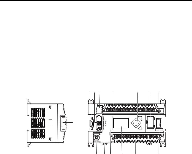
The Bulletin 1766, MicroLogix 1400 programmable controller contains a power supply, input and output circuits, a processor, an isolated combination RS-232/485 communication port, an Ethernet port, and a non-isolated RS-232 communication port. Each controller supports 32 discrete I/O points(20 digital inputs, 12 discrete outputs) and 6 analog I/O points(4 analog inputs and 2 analog outputs : 1766-L32BWAA, 1766-AWAA and 1766-BXBA only).
The hardware features of the controller are shown below.
1 |
44514 |
Left side view
1 |
2 |
3 |
|
4 |
|
5 |
6 |
7 |
|
|
|
|
|
|
|
ESC |
|
|
|
|
|
|
|
|
OK |
|
|
|
|
|
|
|
|
|
44515 |
|
13 |
|
12 |
11 |
10 |
9 |
|
8 |
|
|
|
|
|
Top view |
|
|
|
|
Description |
|
|
1 |
Comm port 2 - 9-pin D-Shell RS-232C connector |
|
|
2 |
Memory module (refer to MicroLogix 1400 Memory Module Installation Instructions, publication 1766-IN010A for instructions on installing the |
|
memory module). |
|
|
3 |
User 24V (for 1766-BWA and 1766-BWAA only) |
|
|
4 |
Input terminal block |
|
|
5 |
LCD Display Keypad (ESC, OK, Up, Down, Left, Right) |
|
|
6 |
Battery compartment |
|
|
7 |
1762 expansion bus connector |
|
|
8 |
Battery connector |
|
|
9 |
Output terminal block |
|
|
10 |
LCD Display |
|
|
Rockwell Automation Publication 1766-UM001H-EN-P - May 2014 |
1 |

Chapter 1 Hardware Overview
Description
11Indicator LED panel
12Comm port 1 - RJ45 connector
13Comm port 0 - 8-pin mini DIN RS-232C/RS-485 connector
Controller Input and Output Description
Catalog Number |
Description |
|
|
|
|
|
|
|
|
|
|
|
|
||
|
Input |
User |
Embedded |
Embedded |
Comm. Ports |
||
|
Power |
Power |
Discrete I/O |
Analog I/O |
|
||
|
|
|
|
|
|
||
1766-L32BWA |
100/240V AC |
24V DC |
12 Fast 24V DC Inputs |
None |
1 RS232/RS485(1) |
||
|
|
|
8 |
Normal 24V DC Inputs |
|
1 Ethernet |
|
|
|
|
12 |
Relay Outputs |
|
1 RS232(2) |
|
1766-L32AWA |
|
None |
20 120V AC Inputs |
|
|
||
|
|
|
12 Relay Outputs |
|
|
||
|
|
|
|
|
|
||
1766-L32BXB |
24V DC |
|
12 Fast 24V DC Inputs |
|
|
||
|
|
|
8 |
Normal 24V DC Inputs |
|
|
|
|
|
|
6 |
Relay Outputs |
|
|
|
|
|
|
3 |
Fast DC Outputs |
|
|
|
|
|
|
3 |
Normal DC Outputs |
|
|
|
|
|
|
|
|
|
||
1766-L32BWAA |
100/240V AC |
24V DC |
12 Fast 24V DC Inputs |
4 Voltage Inputs |
|
||
|
|
|
8 |
Normal 24V DC Inputs |
2 Voltage |
|
|
|
|
|
12 Relay Outputs |
Outputs |
|
||
|
|
|
|
|
|
||
1766-L32AWAA |
|
None |
20 120V AC Inputs |
|
|
||
|
|
|
12 Relay Outputs |
|
|
||
|
|
|
|
|
|
||
1766-L32BXBA |
24V DC |
|
12 Fast 24V DC Inputs |
|
|
||
|
|
|
8 |
Normal 24V DC Inputs |
|
|
|
|
|
|
6 |
Relay Outputs |
|
|
|
|
|
|
3 |
Fast DC Outputs |
|
|
|
|
|
|
3 |
Normal DC Outputs |
|
|
|
|
|
|
|
|
|
|
|
(1)Isolated RS-232/RS-485 combo port.
(2)Non-isolated RS-232. Standard D-sub connector
Component Descriptions MicroLogix 1400 Memory Module and Built-in Real-Time Clock
The controller has a built-in real-time clock to provide a reference for applications that need time-based control.
The controller is shipped with a memory module port cover in place. You can order a memory module, 1766-MM1, as an accessory. The memory module provides optional backup of your user program and data, and is a means to transport your programs between controllers.
The program and data in your MicroLogix 1400 is non-volatile and is stored when the power is lost to the controller. The memory module provides additional backup that can be stored separately. The memory module does not increase the available memory of the controller.
2 |
Rockwell Automation Publication 1766-UM001H-EN-P - May 2014 |
Hardware Overview |
Chapter 1 |
|
|
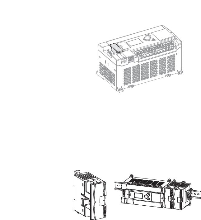
Figure 1 - 1766-MM1 Memory Module
|
ory |
|
em |
|
|
M |
|
ule |
|
od |
|
M |
|
|
44536
1762 Expansion I/O
1762 expansion I/O can be connected to the MicroLogix 1400 controller, as shown below.
TIP |
|
A maximum of seven I/O modules, in any combination, can be |
|
|
connected to a controller. See Appendix H to determine how much |
|
|
heat a certain combination generates. |
Figure 2 - |
1762 Expansion I/O |
|
1762 Expansion I/O |
1762 Expansion I/O Connected to MicroLogix 1400 Controller |
|
44581 44563
Expansion I/O
Catalog Number |
Description |
|
|
Digital |
|
|
|
1762-IA8 |
8-Point 120V AC Input Module |
|
|
1762-IQ8 |
8-Point Sink/Source 24V DC Input Module |
|
|
1762-IQ16 |
16-Point Sink/Source 24V DC Input Module |
|
|
1762-IQ32T |
32-Point Sink/Source 24V DC Input Module |
|
|
1762-OA8 |
8-Point 120/240V AC Triac Output Module |
|
|
1762-OB8 |
8-Point Sourcing 24V DC Output Module |
|
|
Rockwell Automation Publication 1766-UM001H-EN-P - May 2014 |
3 |
Chapter 1 Hardware Overview
Expansion I/O
Catalog Number |
Description |
|
|
1762-OB16 |
16-Point Sourcing 24V DC Output Module |
|
|
1762-OB32T |
32-Point Sourcing 24V DC Output Module |
|
|
1762-OV32T |
32-Point Sinking 24V DC Output Module |
|
|
1762-OW8 |
8-Point AC/DC Relay Output Module |
|
|
1762-OW16 |
16-Point AC/DC Relay Output Module |
|
|
1762-OX6I |
6-Point Isolated AC/DC Relay Output Module |
|
|
1762-IQ8OW6 |
8-Point Sink/Source 24V DC Input and 6-Point AC/DC Relay Output |
|
Module |
|
|
Analog |
|
|
|
1762-IF4 |
4-Channel Voltage/Current Analog Input Module |
|
|
1762-OF4 |
4-Channel Voltage/Current Analog Output Module |
|
|
1762-IF2OF2 |
Combination 2-Channel Input 2-Channel Output Voltage/Current |
|
Analog Module |
|
|
Temperature |
|
|
|
1762-IR4 |
4-Channel RTD/Resistance Input Module |
|
|
1762-IT4 |
4-Channel Thermocouple/mV Input Module |
|
|
Communication Cables
Use only the following communication cables with the MicroLogix 1400 controllers. These cables are required for Class I Div. 2 applications.
•1761-CBL-AM00 Series C or later
•1761-CBL-AP00 Series C or later
•1761-CBL-PM02 Series C or later
•1761-CBL-HM02 Series C or later
•2707-NC9 Series C or later
•1763-NC01 Series A or later
•1747-CP3 Series A or later
ATTENTION: UNSUPPORTED CONNECTION
Do not connect a MicroLogix 1400 controller to another MicroLogix family controller such as MicroLogix 1000, MicroLogix 1200, MicroLogix 1500, or the network port of a 1747-DPS1 Port Splitter using a 1761-CBL-AM00 (8-pin mini-DIN to 8-pin mini-DIN) cable or equivalent.
This type of connection will cause damage to the RS-232/485 communication port (Channel 0) of the MicroLogix 1400 and/or the controller itself. The communication pins used for RS-485 communications on the MicroLogix 1400 are alternately used for 24V power on the other MicroLogix controllers and the network port of the 1747-DPS1 Port Splitter.
Programming
Programming the MicroLogix 1400 controller is done using
RSLogix 500/RSLogix Micro, Revision 8.10.00 or later for Series A controllers
4 |
Rockwell Automation Publication 1766-UM001H-EN-P - May 2014 |

|
|
Hardware Overview Chapter 1 |
|
|
|
|
and 8.30.00 or later for Series B controllers. Communication cables for |
|
|
programming are available separately from the controller and software. |
|
Communication Options |
The MicroLogix 1400 controllers provide three communications ports, an |
|
|
isolated combination RS-232/485 communication port (Channel 0), an |
|
|
Ethernet port (Channel 1) and a non-isolated RS-232 communication port |
|
|
(Channel 2). |
|
|
The Channel 0 and Channel 2 ports on the MicroLogix 1400 can be connected |
|
|
to the following: |
|
|
• operator interfaces, personal computers, etc. using DF1 Full Duplex |
|
|
|
point-to-point |
|
• |
a DH-485 network |
|
• a DF1 Radio Modem network |
|
|
• a DF1 half-duplex network as an RTU Master or RTU Slave |
|
|
• a Modbus network as an RTU Master or RTU Slave |
|
|
• |
an ASCII network |
• a DeviceNet network as a slave or peer using a DeviceNet Interface (catalog number 1761-NET-DNI)
• an Ethernet network using the Ethernet Interface module (catalog number 1761-NET-ENI, or 1761-NET-ENIW)
• a DNP3 network as a Slave
When connecting to RS-485 network using DH-485, DF1 Half-Duplex Master/Slave, Modbus RTU Master/Slave or DNP3 Slave protocols, the MicroLogix 1400 can be connected directly via Channel 0 without an Advanced Interface Converter, catalog number 1761-NET-AIC. The Channel 0 combo port provides both RS-232 and RS-485 isolated connections. The appropriate electrical interface is selected through your choice of communication cable. The existing MicroLogix 1761 communication cables provide an interface to the RS-232 drivers. The 1763-NC01 cable provides an interface to the RS-485 drivers.
The controller may also be connected to serial devices, such as bar code readers, weigh scales, serial printers, and other intelligent devices, using ASCII. See Default Communication Configuration on page 60 for the configuration settings for Channel 0. MicroLogix 1400 can be connected directly to RS-485 network via channel 0, using ASCII.
The MicroLogix 1400 supports EtherNet/IP communication via the Ethernet communication Channel 1. In addition, either Modbus TCP or DNP3 over IP can be enabled for Channel 1. You can connect your controller to a local area network that provides communication between various devices at 10 Mbps or 100 Mbps. This port supports CIP explicit messaging (message exchange) only. The controller cannot be used for CIP implicit messaging (real-time I/O messaging). The controller also includes an embedded web server which allows
Rockwell Automation Publication 1766-UM001H-EN-P - May 2014 |
5 |

Chapter 1 Hardware Overview
viewing of not only module information, TCP/IP configuration, and diagnostic information, but also includes the data table memory map and data table monitor screen using a standard web browser.
See Chapter 4 for more information on connecting to the available communication options.
6 |
Rockwell Automation Publication 1766-UM001H-EN-P - May 2014 |
Chapter 2
Install Your Controller
Agency Certifications
Compliance to European Union Directives
This chapter shows you how to install your controller. The only tools you require are a flat or Phillips head screwdriver and drill. Topics include:
•agency certifications
•compliance to European Union Directives
•installation considerations
•safety considerations
•power considerations
•preventing excessive heat
•master control relay
•installing a memory module
•using the battery
•controller mounting dimensions
•controller and expansion I/O spacing
•mounting the controller
•mounting 1762 expansion I/O
•connecting 1762 expansion I/O
•UL Listed Industrial Control Equipment for use in Class I, Division 2, Hazardous Locations, Groups A, B, C, D
•CE marked for all applicable directives
•C-Tick marked for all applicable acts
•C-UL Listed Industrial Control Equipment for use in Canada
This product has the CE mark and is approved for installation within the European Union and EEA regions. It has been designed and tested to meet the following directives.
EMC Directive
This product is tested to meet Council Directive 2004/108/EC Electromagnetic Compatibility (EMC) and the following standards, in whole or in part, documented in a technical construction file:
• EN 61131-2; Programmable Controllers (Clause 8, Zone A & B)
Rockwell Automation Publication 1766-UM001H-EN-P - May 2014 |
7 |

Chapter 2 Install Your Controller
•EN 61131-2; Programmable Controllers (Clause 11)
•EN 61000-6-4
EMC - Part 6-4: Generic Standards - Emission Standard for Industrial Environments
•EN 61000-6-2
EMC - Part 6-2: Generic Standards - Immunity for Industrial Environments
This product is intended for use in an industrial environment.
Low Voltage Directive
This product is tested to meet Council Directive 2006/95/ECLow Voltage, by applying the safety requirements of EN 61131-2 Programmable Controllers, Part 2 - Equipment Requirements and Tests.
For specific information required by EN 61131-2, see the appropriate sections in this publication, as well as the following Allen-Bradley publications:
•Industrial Automation Wiring and Grounding Guidelines for Noise Immunity, publication 1770-4.1
•Guidelines for Handling Lithium Batteries, publication AG-5.4
•Automation Systems Catalog, publication B115
Installation Considerations Most applications require installation in an industrial enclosure (Pollution Degree 2(1)) to reduce the effects of electrical interference (Over Voltage
Category II(2)) and environmental exposure. Locate your controller as far as possible from power lines, load lines, and other sources of electrical noise such as hard-contact switches, relays, and AC motor drives. For more information on proper grounding guidelines, see the Industrial Automation Wiring and Grounding Guidelines publication 1770-4.1.
ATTENTION: Electrostatic discharge can damage semiconductor devices inside the controller. Do not touch the connector pins or other sensitive areas.
ATTENTION: Vertical mounting of the controller is not supported due to heat build-up considerations.
(1)Pollution Degree 2 is an environment where normally only non-conductive pollution occurs except that occasionally temporary conductivity caused by condensation shall be expected.
(2)Overvoltage Category II is the load level section of the electrical distribution system. At this level, transient voltages are controlled and do not exceed the impulse voltage capability of the products insulation.
8 |
Rockwell Automation Publication 1766-UM001H-EN-P - May 2014 |
Install Your Controller |
Chapter 2 |
|
|
ATTENTION: Be careful of metal chips when drilling mounting holes for your controller or other equipment within the enclosure or panel. Drilled fragments that fall into the controller or I/O modules could cause damage. Do not drill holes above a mounted controller if the protective debris shields are removed or the processor is installed.
WARNING: Do not place the MicroLogix 1400 Programmable Controller in direct sunlight. Prolonged exposure to direct sunlight could degrade the LCD display and have adverse effects on the controller.
The controller is not designed for outdoor use.
Safety Considerations
Safety considerations are an important element of proper system installation. Actively thinking about the safety of yourself and others, as well as the condition of your equipment, is of primary importance. We recommend reviewing the following safety considerations.
Hazardous Location Considerations
This equipment is suitable for use in Class I, Division 2, Groups A, B, C, D or non-hazardous locations only. The following WARNING statement applies to use in hazardous locations.
WARNING: EXPLOSION HAZARD
• Substitution of components may impair suitability for Class I, Division 2.
•Do not replace components or disconnect equipment unless power has been switched off.
•Do not connect or disconnect components unless power has been switched off.
•This product must be installed in an enclosure. All cables connected to the product must remain in the enclosure or be protected by conduit or other means.
•All wiring must comply with N.E.C. article 501-4(b).
Rockwell Automation Publication 1766-UM001H-EN-P - May 2014 |
9 |
Chapter 2 Install Your Controller
Use only the following communication cables in Class I, Division 2 hazardous locations.
Environment Classification |
Communication Cables |
|
|
Class I, Division 2 Hazardous Environment |
1761-CBL-AC00 Series C or later |
|
|
|
1761-CBL-AM00 Series C or later |
|
|
|
1761-CBL-AP00 Series C or later |
|
|
|
1761-CBL-PM02 Series C or later |
|
|
|
1761-CBL-HM02 Series C or later |
|
|
|
2707-NC9 Series C or later |
|
|
|
1763-NC01 Series A or later |
|
|
|
1747-CP3 Series |
|
|
Disconnecting Main Power
WARNING: Explosion Hazard
Do not replace components, connect equipment, or disconnect equipment unless power has been switched off.
The main power disconnect switch should be located where operators and maintenance personnel have quick and easy access to it. In addition to disconnecting electrical power, all other sources of power (pneumatic and hydraulic) should be de-energized before working on a machine or process controlled by a controller.
Safety Circuits
WARNING: Explosion Hazard
Do not connect or disconnect connectors while circuit is live.
Circuits installed on the machine for safety reasons, like overtravel limit switches, stop push buttons, and interlocks, should always be hard-wired directly to the master control relay. These devices must be wired in series so that when any one device opens, the master control relay is de-energized, thereby removing power to the machine. Never alter these circuits to defeat their function. Serious injury or machine damage could result.
Power Distribution
There are some points about power distribution that you should know:
10 |
Rockwell Automation Publication 1766-UM001H-EN-P - May 2014 |

Install Your Controller |
Chapter 2 |
|
|
•The master control relay must be able to inhibit all machine motion by removing power to the machine I/O devices when the relay is de-energized. It is recommended that the controller remain powered even when the master control relay is de-energized.
•If you are using a DC power supply, interrupt the load side rather than the AC line power. This avoids the additional delay of power supply turn-off. The DC power supply should be powered directly from the fused secondary of the transformer. Power to the DC input and output circuits should be connected through a set of master control relay contacts.
Periodic Tests of Master Control Relay Circuit
Power Considerations
Any part can fail, including the switches in a master control relay circuit. The failure of one of these switches would most likely cause an open circuit, which would be a safe power-off failure. However, if one of these switches shorts out, it no longer provides any safety protection. These switches should be tested periodically to assure they will stop machine motion when needed.
The following explains power considerations for the micro controllers.
Isolation Transformers
You may want to use an isolation transformer in the AC line to the controller. This type of transformer provides isolation from your power distribution system to reduce the electrical noise that enters the controller and is often used as a step-down transformer to reduce line voltage. Any transformer used with the controller must have a sufficient power rating for its load. The power rating is expressed in volt-amperes (VA).
Power Supply Inrush
During power-up, the MicroLogix 1400 power supply allows a brief inrush current to charge internal capacitors. Many power lines and control transformers can supply inrush current for a brief time. If the power source cannot supply this inrush current, the source voltage may sag momentarily.
The only effect of limited inrush current and voltage sag on the MicroLogix 1400 is that the power supply capacitors charge more slowly. However, the effect of a voltage sag on other equipment should be considered. For example, a deep voltage sag may reset a computer connected to the same power source. The following considerations determine whether the power source must be required to supply high inrush current:
Rockwell Automation Publication 1766-UM001H-EN-P - May 2014 |
11 |

Chapter 2 Install Your Controller
•The power-up sequence of devices in a system.
•The amount of the power source voltage sag if the inrush current cannot be supplied.
•The effect of voltage sag on other equipment in the system.
If the entire system is powered-up at the same time, a brief sag in the power source voltage typically will not affect any equipment.
Loss of Power Source
The power supply is designed to withstand brief power losses without affecting the operation of the system. The time the system is operational during power loss is called program scan hold-up time after loss of power. The duration of the power supply hold-up time depends on the type and state of the I/O, but is typically between 10 milliseconds and 3 seconds. When the duration of power loss reaches this limit, the power supply signals the processor that it can no longer provide adequate DC power to the system. This is referred to as a power supply shutdown. The processor then performs an orderly shutdown of the controller.
Input States on Power Down
The power supply hold-up time as described above is generally longer than the turn-on and turn-off times of the inputs. Because of this, the input state change from “On” to “Off ” that occurs when power is removed may be recorded by the processor before the power supply shuts down the system. Understanding this concept is important. The user program should be written to take this effect into account.
Other Types of Line Conditions
Occasionally the power source to the system can be temporarily interrupted. It is also possible that the voltage level may drop substantially below the normal line voltage range for a period of time. Both of these conditions are considered to be a loss of power for the system.
Preventing Excessive Heat For most applications, normal convective cooling keeps the controller within the specified operating range. Ensure that the specified temperature range is
maintained. Proper spacing of components within an enclosure is usually sufficient for heat dissipation.
In some applications, a substantial amount of heat is produced by other equipment inside or outside the enclosure. In this case, place blower fans inside
12 |
Rockwell Automation Publication 1766-UM001H-EN-P - May 2014 |
Install Your Controller |
Chapter 2 |
|
|
Master Control Relay
the enclosure to assist in air circulation and to reduce “hot spots” near the controller.
Additional cooling provisions might be necessary when high ambient temperatures are encountered.
TIP |
Do not bring in unfiltered outside air. Place the controller in an |
|
enclosure to protect it from a corrosive atmosphere. Harmful |
|
contaminants or dirt could cause improper operation or damage to |
|
components. In extreme cases, you may need to use air conditioning to |
|
protect against heat build-up within the enclosure. |
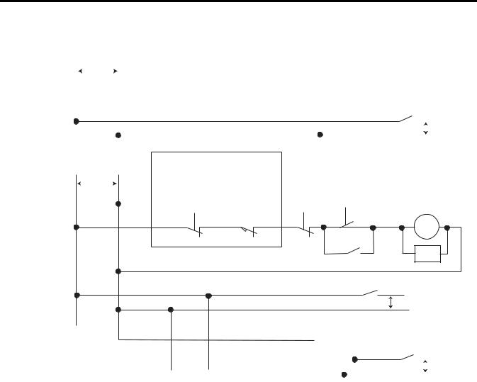
A hard-wired master control relay (MCR) provides a reliable means for emergency machine shutdown. Since the master control relay allows the placement of several emergency-stop switches in different locations, its installation is important from a safety standpoint. Overtravel limit switches or mushroom-head push buttons are wired in series so that when any of them opens, the master control relay is de-energized. This removes power to input and output device circuits. Refer to the figures on pages 15 and 16.
ATTENTION: Never alter these circuits to defeat their function since serious injury and/or machine damage could result.
TIP |
If you are using an external DC power supply, interrupt the DC output |
|
side rather than the AC line side of the supply to avoid the additional |
|
delay of power supply turn-off. |
|
The AC line of the DC output power supply should be fused. |
|
Connect a set of master control relays in series with the DC power |
|
supplying the input and output circuits. |
Place the main power disconnect switch where operators and maintenance personnel have quick and easy access to it. If you mount a disconnect switch inside the controller enclosure, place the switch operating handle on the outside of the enclosure, so that you can disconnect power without opening the enclosure.
Whenever any of the emergency-stop switches are opened, power to input and output devices should be removed.
When you use the master control relay to remove power from the external I/O circuits, power continues to be provided to the controller’s power supply so that diagnostic indicators on the processor can still be observed.
The master control relay is not a substitute for a disconnect to the controller. It is intended for any situation where the operator must quickly de-energize I/O devices only. When inspecting or installing terminal connections, replacing
Rockwell Automation Publication 1766-UM001H-EN-P - May 2014 |
13 |

Chapter 2 Install Your Controller
output fuses, or working on equipment within the enclosure, use the disconnect to shut off power to the rest of the system.
TIP |
Do not control the master control relay with the controller. Provide |
|
the operator with the safety of a direct connection between an |
|
emergency-stop switch and the master control relay. |
Using Emergency-Stop Switches
When using emergency-stop switches, adhere to the following points:
•Do not program emergency-stop switches in the controller program. Any emergency-stop switch should turn off all machine power by turning off the master control relay.
•Observe all applicable local codes concerning the placement and labeling of emergency-stop switches.
•Install emergency-stop switches and the master control relay in your system. Make certain that relay contacts have a sufficient rating for your application. Emergency-stop switches must be easy to reach.
•In the following illustration, input and output circuits are shown with MCR protection. However, in most applications, only output circuits require MCR protection.
The following illustrations show the Master Control Relay wired in a grounded system.
TIP |
In most applications input circuits do not require MCR protection; |
|
however, if you need to remove power from all field devices, you must |
|
include MCR contacts in series with input power wiring. |
14 |
Rockwell Automation Publication 1766-UM001H-EN-P - May 2014 |
Install Your Controller Chapter 2
Schematic (Using IEC Symbols)
|
|
L1 |
L2 |
|
|
|
|
|
|
|
|
|
|
|
|
|
|
|
|
|
|
|
|
|
|
|
|
|
|
|
|||||||||||||
|
|
|
|
230V AC |
|
|
|
|
|
|
|
|
|
|
|
|
|
|
|
|
|
|
|
|
|
|
|
|
|
|
|
|
|
|
|
|
|
||||||
|
|
|
|
|
|
|
|
|
|
|
|
|
|
|
|
|
|
|
|
|
|
|
|
|
|
|
|
|
|
|
|
|
|
|
|
||||||||
|
|
|
|
|
|
|
|
|
|
|
|
|
|
|
|
|
|
|
|
|
|
|
|
|
|
|
|
|
|
|
|
|
|
|
|
|
|
|
|
|
|
|
|
|
|
|
|
|
|
|
|
|
|
|
|
|
|
|
|
|
|
|
|
|
|
|
|
|
|
|
|
|
|
|
|
|
|
|
|
|
|
|
|
|
|
|
|
|
|
|
|
Disconnect |
|
|
|
|
|
|
|
|
|
|
|
|
|
|
|
|
|
|
|
|
|
|
|
|
|
|
|
|
|
|
|
||||||||
|
|
|
|
|
|
|
|
|
|
|
|
|
|
|
|
|
|
|
|
|
|
|
|
|
|
|
|
|
|
|
|
|
|
|
|
|
Fuse |
MCR |
|||||
|
|
|
|
|
|
|
|
|
|
|
|
|
|
|
|
|
|
|
|
|
|
|
|
|
|
|
|
|
|
|
|
|
|
|
|
|
|
|
|
|
|
|
230V AC |
|
|
|
|
|
|
|
|
|
|
|
|
|
|
|
|
|
|
|
|
|
|
|
|
|
|
|
|
|
|
|
|
|
|
|
|
|
|
|
|
|
|
|
|
|
|
|
|
|
|
|
|
|
|
|
|
|
|
|
|
|
|
|
|
|
|
|
|
|
|
|
|
|
|
|
|
|
|
|
|
|
|
|
|
|
|
|
I/O |
|
|
|
|
|
|
|
|
|
|
|
|
|
|
|
|
|
|
|
|
|
|
|
|
|
|
|
|
|
|
|
|
|
|
|
|
|
|
|
|
|
|
|
|
|
|
|
|
|
|
|
|
|
|
|
|
|
|
|
|
|
|
|
|
|
|
|
|
|
|
|
|
|
|
|
|
|
|
|
|
|
|
|
|
|
|
|
Circuits |
|
|
|
|
|
|
|
|
|
|
|
|
|
|
|
|
|
|
|
|
|
|
|
|
|
|
|
|
|
|
|
|
|
|
|
|
|
|
|
|
|
|
|
|
|
|
|
|
|
|
|
|
|
|
|
|
|
|
|
|
|
|
|
|
|
|
|
|
|
|
|
|
|
|
|
|
|
|
|
|
|
|
|
|
|
|
|
|
|
|
|
Isolation |
|
|
|
|
|
|
|
|
|
Operation of either of these contacts will |
|
|
|
|
|
|
|
|
|
|
|
|
|
|||||||||||||||||
|
|
|
Transformer |
|
|
|
|
|
|
|
|
|
remove power from the external I/O |
|
|
|
|
|
|
|
Master Control Relay (MCR) |
||||||||||||||||||||||
|
|
|
|
|
|
|
|
|
|
|
|
|
|
|
|
|
|
|
|
circuits, stopping machine motion. |
|
|
|
|
|
|
|
||||||||||||||||
X1 |
115V AC |
|
|
X2 |
|
|
|
|
|
|
|
|
|
|
Cat. No. 700-PK400A1 |
||||||||||||||||||||||||||||
|
|
|
|
|
|
|
|
|
|
|
|
|
|
|
|
|
|
|
|
|
|
|
|
||||||||||||||||||||
|
|
|
|
or 230V AC |
|
|
|
Emergency-Stop |
Stop |
|
|
Start |
Suppressor |
||||||||||||||||||||||||||||||
|
|
|
|
Fuse |
|
|
|
|
|
|
|
|
|
Push Button |
Overtravel |
|
|
|
|
|
|
|
Cat. No. 700-N24 |
||||||||||||||||||||
|
|
|
|
|
|
|
|
|
|
|
|
|
|
|
|
|
|
|
|
|
|
|
|
|
Limit Switch |
|
|
|
|
|
|
|
|
|
|
|
|
|
|
|
|||
|
|
|
|
|
|
|
|
|
|
|
|
|
|
|
|
|
|
|
|
|
|
|
|
|
|
|
|
|
|
|
|
|
|
|
|
|
|
|
|
||||
MCR |
Suppr. |
MCR |
MCR |
115V AC or
230V AC I/O Circuits
|
|
|
DC Power Supply. |
|
|
|
|
|
||
|
|
|
|
|
|
|
|
|||
|
|
|
Use IEC 950/EN 60950 |
MCR |
|
|
||||
|
|
|
|
|
|
|
|
|||
|
|
_ |
|
+ |
|
|
|
|
24V DC |
|
(Lo) |
(Hi) |
|
|
|
|
|
|
|
||
|
|
|
|
|
|
|
|
|||
|
|
|
|
|
|
|
|
I/O |
||
Line Terminals: Connect to terminals of Power |
|
|
|
|
|
|
|
|
||
Line Terminals: |
|
|
|
|
|
|
Circuits |
|||
|
|
|
|
|
|
|||||
Supply (1766-L32AWA, 1766-L32AWAA, |
Connect to 24V DC terminals of |
|||||||||
1766-L32BWA, 1766-L32BWAA). |
Power Supply (1766-L32BXB, 1766-L32BXBA) |
44564 |
||||||||
|
|
|
|
|
|
|
|
|
||
Rockwell Automation Publication 1766-UM001H-EN-P - May 2014 |
15 |
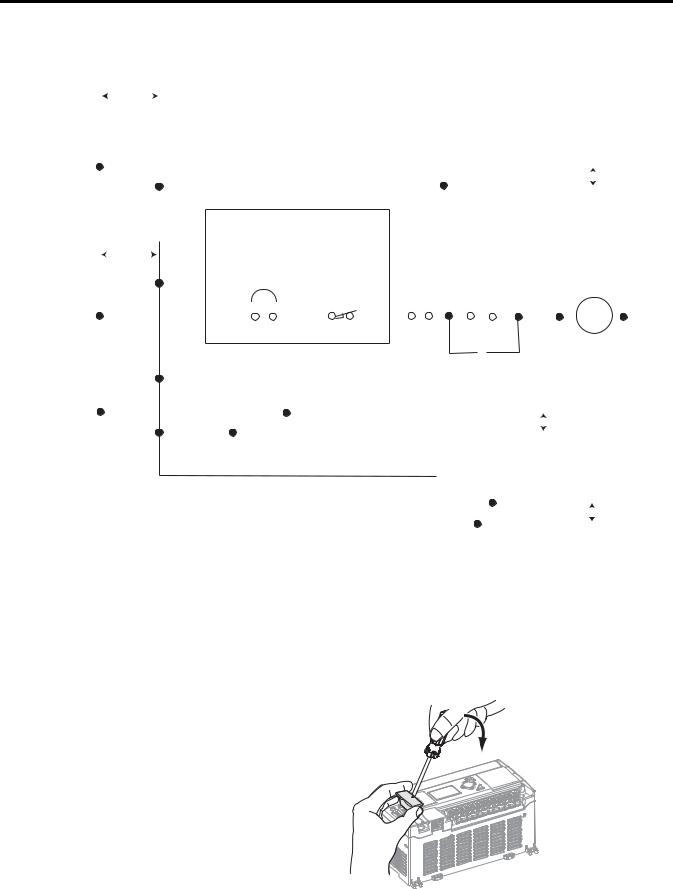
Chapter 2 Install Your Controller
Schematic (Using ANSI/CSA Symbols)
|
L1 |
|
230V AC L2 |
|
|
|
|
|
|
|
|
|
|
|
|
|
|
|
|
|
|
|
|
|
|
|
|
|
|
|
|
|
|
|
|
|
|
|
|
|
|
|
|
|
|
|
|
|
|
|
|
|
|
|
|
|
|
|
|
|
|
|||||
|
|
|
|
|
|
|
|
|
|
|
|
|
|
|
|
|
|
|
|
|
|
|
|
|
|
|
|
|
|
|
|
|
|
|
|
|
|
|
|
|
|
|
|
|
|
|
|
|
|
|
|
|
|
|
|
|
|
|
|
|||||||
|
|
|
|
|
|
|
|
|
|
|
|
|
|
|
|
|
|
|
|
|
|
|
|
|
|
|
|
|
|
|
|
|
|
|
|
|
|
|
|
|
|
|
|
|
|
|
|
|
|
|
|
|
|
|
|
|
|
|
|
|
|
|
|
|
|
|
|
|
Disconnect |
|
|
|
|
|
|
|
|
|
|
|
|
|
|
|
|
|
|
|
|
|
|
|
|
|
|
|
|
|
|
|
|
|
|
|
|
|
|
|
|
|
|
|
|
|
|
|
|
|
|
|
|
|
|
|
|
||||||||
|
|
|
|
|
|
|
|
|
|
|
|
|
|
|
|
|
|
|
|
|
|
|
|
|
|
|
|
|
|
|
|
|
|
|
|
|
|
|
|
|
Fuse |
|
|
|
|
|
|
|
MCR |
230V |
AC |
|||||||||||||||
|
|
|
|
|
|
|
|
|
|
|
|
|
|
|
|
|
|
|
|
|
|
|
|
|
|
|
|
|
|
|
|
|
|
|
|
|
|
|
|
|
||||||||||||||||||||||||||
|
|
|
|
|
|
|
|
|
|
|
|
|
|
|
|
|
|
|
|
|
|
|
|
|
|
|
|
|
|
|
|
|
|
|
|
|
|
|
|
|
|
|
|
|
|
|
|
|
|
|
|
|
|
|
|
|
|
|
|
|
|
|
|
|||
|
|
|
|
|
|
|
|
|
|
|
|
|
|
|
|
|
|
|
|
|
|
|
|
|
|
|
|
|
|
|
|
|
|
|
|
|
|
|
|
|
|
|
|
|
|
|
|
|
|
|
|
|
|
|
|
|
|
|
|
|
|
|
|
Output |
|
|
|
|
|
|
|
|
|
|
|
|
|
|
|
|
|
|
|
|
|
|
|
|
|
|
|
|
|
|
|
|
|
|
|
|
|
|
|
|
|
|
|
|
|
|
|
|
|
|
|
|
|
|
|
|
|
|
|
|
|
|
|
|
|
|
|
||
|
|
|
|
|
|
|
|
|
|
|
|
|
|
|
|
|
|
|
|
|
|
|
|
|
|
|
|
|
|
|
|
|
|
|
|
|
|
|
|
|
|
|
|
|
|
|
|
|
|
|
|
|
|
|
|
|
|
|
|
|
|
|
|
Circuits |
||
|
|
|
|
|
|
|
|
|
|
|
|
|
|
|
|
|
|
|
|
|
|
|
|
|
|
|
|
|
|
|
|
|
|
|
|
|
|
|
|
|
|
|
|
|
|
|
|
|
|
|
|
|
|
|
|
|
|
|
|
|
|
|
|
|||
|
|
|
|
|
|
|
|
|
|
|
|
|
|
|
|
|
|
|
|
|
|
|
|
|
|
|
|
|
|
|
|
|
|
|
|
|
|
|
|
|
|
|
|
|
|
|
|
|
|
|
|
|
|
|
|
|
|
|
|
|
|
|
|
|||
|
|
|
|
|
|
|
|
|
|
|
|
|
|
|
|
|
|
|
|
|
|
|
|
|
|
|
|
|
|
|
|
|
|
|
|
|
|
|
|
|
|
|
|
|
|
|
|
|
|
|
|
|
|
|
|
|
|
|
|
|
|
|
|
|
|
|
|
|
Isolation |
|
|
|
|
|
|
|
|
Operation of either of these contacts will |
|
|
|
|
|
|
|
|
|
|
|
|
|
|
|
|
|
|
|
|
|
|
|
|
|
|
|
|
|
|
|
|
|
|
|
|
|
||||||||||||||||||
|
|
Transformer |
|
|
|
|
|
|
|
|
|
|
|
|
|
|
|
|
|
|
|
|
|
|
|
|
|
|
|
|
|
|
|
|
|
|
|
|
|
|
|
|
|
|
|
|
|
|||||||||||||||||||
|
|
|
|
|
|
|
|
|
|
remove power from the external I/O |
|
|
|
|
|
|
|
|
|
|
|
|
|
|
|
|
|
|
|
|
|
|
Master Control Relay (MCR) |
|||||||||||||||||||||||||||||||||
|
|
|
|
|
|
|
|
|
|
|
|
|
|
|
|
|
|
|
|
|
|
|
|
|
|
|
|
|
|
|
|
|
|
|
|
|
|
|
|
|
||||||||||||||||||||||||||
|
|
|
|
|
|
|
|
|
|
|
|
|
|
|
|
|
|
|
circuits, stopping machine motion. |
|
|
|
|
|
|
|
|
|
|
|
|
|
|
|
|
|
|
|
|
|
|
|||||||||||||||||||||||||
|
X1 |
|
115V AC or |
X2 |
|
|
|
|
|
|
|
|
|
|
|
|
|
|
|
|
|
|
|
|
|
|
|
|
|
Cat. No. 700-PK400A1 |
||||||||||||||||||||||||||||||||||||
|
|
|
|
|
|
|
|
|
|
|
|
|
|
Emergency-Stop |
|
|
|
|
|
|
|
|
|
|
|
|
|
|
|
|
|
|
|
|
|
|
|
|
|
|||||||||||||||||||||||||||
|
|
|
230V AC |
|
|
|
|
|
|
|
|
|
|
|
|
|
|
|
|
|
|
|
|
|
|
|
|
|
|
|
|
|
|
|
|
|
|
|
|
Suppressor |
|
|
|
|||||||||||||||||||||||
|
|
|
Fuse |
|
|
|
|
|
|
|
|
|
|
|
Push Button |
Overtravel |
Stop |
|
|
|
|
|
|
|
Start |
|
|
|
|
|
|
|
Cat. No. 700-N24 |
|||||||||||||||||||||||||||||||||
|
|
|
|
|
|
|
|
|
|
|
|
|
|
|
|
|
|
|
|
|
|
|
|
|
|
|
|
|
|
|
|
|
|
|
|
|
|
|
|
|
|
|
|
|
|
|
|
|
|
|
|
|
|
|
||||||||||||
|
|
|
|
|
|
|
|
|
|
|
|
|
|
|
|
|
|
|
|
|
|
|
|
|
|
|
Limit Switch |
|
|
|
|
|
|
|
|
|
|
|
|
|
|
|
|
|
|
|
|
|
|
|
|
|
|
|
|
|
|
MCR |
|
|
|
|
||||
|
|
|
|
|
|
|
|
|
|
|
|
|
|
|
|
|
|
|
|
|
|
|
|
|
|
|
|
|
|
|
|
|
|
|
|
|
|
|
|
|
|
|
|
|
|
|
|
|
|
|
|
|
|
|
|
|
|
|
|
|
||||||
|
|
|
|
|
|
|
|
|
|
|
|
|
|
|
|
|
|
|
|
|
|
|
|
|
|
|
|
|
|
|
|
|
|
|
|
|
|
|
|
|
|
|
|
|
|
|
|
|
|
|
|
|
|
|
|
|
|
|
|
|
|
|
|
|||
|
|
|
|
|
|
|
|
|
|
|
|
|
|
|
|
|
|
|
|
|
|
|
|
|
|
|
|
|
|
|
|
|
|
|
|
|
|
|
|
|
|
|
|
|
|
|
|
|
|
|
|
|
|
|
|
|
|
|
|
|
|
|
|
|
|
|
|
|
|
|
|
|
|
|
|
|
|
|
|
|
|
|
|
|
|
|
|
|
|
|
|
|
|
|
|
|
|
|
|
|
|
|
|
|
|
|
|
|
|
|
|
|
|
|
|
|
|
|
|
|
|
|
|
|
|
|
Suppr. |
|
|
|
|||
|
|
|
|
|
|
|
|
|
|
|
|
|
|
|
|
|
|
|
|
|
|
|
|
|
|
|
|
|
|
|
|
|
|
|
|
|
|
|
|
|
|
|
|
|
|
|
|
|
|
|
|
|
|
|
|
|
|
|
|
|
|
|
||||
|
|
|
|
|
|
|
|
|
|
|
|
|
|
|
|
|
|
|
|
|
|
|
|
|
|
|
|
|
|
|
|
|
|
|
|
|
|
|
|
|
MCR |
|
|
|
|
|
|
|
|
|
|
|
|
|
|
|
|
|
|
|
|
|||||
|
|
|
|
|
|
|
|
|
|
|
|
|
|
|
|
|
|
|
|
|
|
|
|
|
|
|
|
|
|
|
|
|
|
|
|
|
|
|
|
|
|
|
|
|
|
|
|
|
|
|
|
|
|
|
||||||||||||
|
|
|
|
|
|
|
|
|
|
|
|
|
|
|
|
|
|
|
|
|
|
|
|
|
|
|
|
|
|
|
|
|
|
|
|
|
|
|
|
|
|
|
|
|
|
|
|
|
|
|
|
|
|
|
|
|
|
|
|
|
|
|
|
|
|
|
|
|
|
|
|
|
|
|
|
|
|
|
|
|
|
|
|
|
|
|
|
|
|
|
|
|
|
|
|
|
|
|
|
|
|
|
|
|
|
|
|
|
|
|
|
|
|
|
MCR |
|
|
|
|
|
|
115V AC or |
|||||||||||
|
|
|
|
|
|
|
|
|
|
|
|
|
|
|
|
|
|
|
|
|
|
|
|
|
|
|
|
|
|
|
|
|
|
|
|
|
|
|
|
|
|
|
|
|
|
|
|
|
|
|
|
|
|
|
|
|
|
|||||||||
|
|
|
|
|
|
|
|
|
|
|
|
|
|
|
|
|
|
|
|
|
|
|
|
|
|
|
|
|
|
|
|
|
|
|
|
|
|
|
|
|
|
|
|
|
|
|
|
|
|
|
|
|
|
|
|
|
|
|||||||||
|
|
|
|
|
|
|
|
|
|
|
|
|
|
|
|
|
|
|
|
|
|
|
|
|
|
|
|
|
|
|
|
|
|
|
|
|
|
|
|
|
|
|
|
|
|
|
|
|
|
|
|
|
|
|
|
|
|
230V AC |
|
|
|
|||||
|
|
|
|
|
|
|
|
|
|
|
|
|
|
|
|
|
|
|
|
|
|
|
|
|
|
|
|
|
|
|
|
|
|
|
|
|
|
|
|
|
|
|
|
|
|
|
|
|
|
|
|
|
|
|
|
|
|
|
|
|
||||||
|
|
|
|
|
|
|
|
|
|
|
|
|
|
|
|
|
|
|
|
|
|
|
|
|
|
|
|
|
|
|
|
|
|
|
|
|
|
|
|
|
|
|
|
|
|
|
|
|
|
|
|
|
|
|
|
|
|
I/O Circuits |
||||||||
|
|
|
|
|
|
|
|
|
|
|
|
|
|
|
|
|
|
|
|
|
|
|
|
|
|
|
|
|
|
|
|
|
|
|
|
|
|
|
|
|
|
|
|
|
|
|
|
|
|
|
|
|
|
|
|
|
|
|||||||||
|
|
|
|
|
|
|
|
|
|
|
|
|
|
|
|
|
|
|
|
|
|
|
|
|
|
|
|
|
|
|
|
|
|
|
|
|
|
|
|
|
|
|
|
|
|
|
|
|
|
|
|
|
|
|
|
|
|
|||||||||
|
|
|
|
|
|
|
|
|
|
|
|
|
|
|
|
|
|
|
|
|
|
|
|
|
|
|
|
|
|
|
|
|
|
|
|
|
|
|
|
|
|
|
|
|
|
|
|
|
|
|
|
|
|
|
|
|
|
|
|
|
|
|
|
|
|
|
|
|
|
|
|
|
|
|
|
|
|
|
|
|
|
|
|
|
|
|
|
|
|
|
|
|
|
|
|
|
|
|
|
|
|
|
DC Power Supply. Use |
|
|
|
|
|
|
|
|
|
|
|
|
|
|
|
|||||||||||||||
|
|
|
|
|
|
|
|
|
|
|
|
|
|
|
|
|
|
|
|
|
|
|
|
|
|
|
|
|
|
|
|
|
|
|
|
NEC Class 2 for UL |
|
|
|
|
|
|
|
|
|
|
|
|
|
|
|
|||||||||||||||
|
|
|
|
|
|
|
|
|
|
|
|
|
|
|
|
|
|
|
|
|
|
|
|
|
|
|
|
|
|
|
|
|
|
|
|
Listing. |
|
|
|
|
|
|
|
MCR |
|
|
|
|||||||||||||||||||
|
|
|
|
|
|
|
|
|
|
|
|
|
|
|
|
|
|
|
(Lo) |
|
|
|
|
|
|
(Hi) |
|
|
|
|
|
|
|
|
_ |
|
|
|
|
|
|
|
+ |
|
|
|
|
|
|
|
|
|
|
|
|
|
|
|
24 V DC |
|||||||
|
|
|
|
|
|
|
|
|
|
|
|
|
|
|
|
|
|
|
|
|
|
|
|
|
|
|
|
|
|
|
|
|
|
|
|
|
|
|
|
|
|
|
|
|
|
|
|
|
|
|
|
|
|
|
||||||||||||
|
|
|
|
|
|
|
|
|
|
|
|
|
|
|
|
|
|
|
|
|
|
|
|
|
|
|
|
|
|
|
|
|
|
|
|
|
|
|
|
|
|
|
|
|
|
|
|
|
|
|
|
|
|
|
|
|
|
|
|
|
|
|||||
|
|
|
|
|
|
|
|
|
|
|
|
|
|
|
|
|
|
|
|
|
|
|
|
|
|
|
|
|
|
|
|
|
|
|
|
|
|
|
|
|
|
|
|
|
|
|
|
|
|
|
|
|
|
|
|
|
|
|
|
|
|
|||||
|
|
|
|
|
|
|
|
|
|
|
|
|
|
|
|
|
|
|
|
|
|
|
|
|
|
|
|
|
|
|
|
|
|
|
|
|
|
|
|
|
|
|
|
|
|
|
|
|
|
|
|
|
|
|
|
|
|
|
|
|
|
|
|
I/O |
||
|
|
|
|
|
|
|
|
|
|
|
|
|
|
|
|
|
|
|
|
|
|
|
|
|
|
|
|
|
|
|
|
|
|
|
|
|
|
|
|
|
|
|
|
|
|
|
|
|
|
|
|
|
|
|
|
|
|
|
|
|
|
|
|
|||
|
|
|
|
|
|
|
|
|
|
|
|
|
|
|
|
|
|
Line Terminals: Connect to terminals of Power |
|
|
|
|
|
|
|
|
|
|
|
|
|
|
|
|
|
|
|
|
|
|
|
|
|
|
|
|
|
|
|
|
|
|
Circuits |
|||||||||||||
|
|
|
|
|
|
|
|
|
|
|
|
|
|
|
|
|
|
|
|
|
|
|
|
|
|
|
|
|
|
|
|
|
|
|
|
|
|
|
|
|
|
|
|
|
|
|
|
|
|
|||||||||||||||||
|
|
|
|
|
|
|
|
|
|
|
|
|
|
|
|
|
|
Supply (1766-L32AWA, 1766-L32AWAA, |
|
|
|
Line Terminals: Connect to 24V DC terminals of |
||||||||||||||||||||||||||||||||||||||||||||
|
|
|
|
|
|
|
|
|
|
|
|
|
|
|
|
|
|
1766-L32BWA, 1766-L32BWAA). |
|
|
|
|||||||||||||||||||||||||||||||||||||||||||||
|
|
|
|
|
|
|
|
|
|
|
|
|
|
|
|
|
|
|
|
|
Power Supply (1766-L32BXB, 1766-L32BXBA). |
|||||||||||||||||||||||||||||||||||||||||||||
|
|
|
|
|
|
|
|
|
|
|
|
|
|
|
|
|
|
|
|
|
|
|
|
|
|
|
|
|
|
|
|
|
||||||||||||||||||||||||||||||||||
|
|
|
|
|
|
|
|
|
|
|
|
|
|
|
|
|
|
|
|
|
|
|
|
|
|
|
|
|
|
|
|
|
|
|
|
|
|
|
|
|
|
|
|
|
|
|
|
|
|
|
|
|
|
|
|
|
|
|
|
|
|
|
|
44565 |
||
Installing a Memory
Module
1. Remove the memory module port cover.
44534
16 |
Rockwell Automation Publication 1766-UM001H-EN-P - May 2014 |
Loading...