


 Loading...
User Manual
Compact High-speed Counter Module
Catalog Number 1769-HSC

Important User Information
Solid-state equipment has operational characteristics differing from those of electromechanical equipment. Safety Guidelines for the Application, Installation and Maintenance of Solid State Controls (publication SGI-1.1 available from your local Rockwell Automation sales office or online at http://www.rockwellautomation.com/literature/) describes some important differences between solid-state equipment and hard-wired electromechanical devices. Because of this difference, and also because of the wide variety of uses for solid-state equipment, all persons responsible for applying this equipment must satisfy themselves that each intended application of this equipment is acceptable.
In no event will Rockwell Automation, Inc. be responsible or liable for indirect or consequential damages resulting from the use or application of this equipment.
The examples and diagrams in this manual are included solely for illustrative purposes. Because of the many variables and requirements associated with any particular installation, Rockwell Automation, Inc. cannot assume responsibility or liability for actual use based on the examples and diagrams.
No patent liability is assumed by Rockwell Automation, Inc. with respect to use of information, circuits, equipment, or software described in this manual.
Reproduction of the contents of this manual, in whole or in part, without written permission of Rockwell Automation,
Inc., is prohibited.
Throughout this manual, when necessary, we use notes to make you aware of safety considerations.
WARNING: Identifies information about practices or circumstances that can cause an explosion in a hazardous environment, which can lead to personal injury or death, property damage, or economic loss.
ATTENTION: Identifies information about practices or circumstances that can lead to personal injury or death, property damage, or economic loss. Attentions help you identify a hazard, avoid a hazard, and recognize the consequence
SHOCK HAZARD: Labels can be on or inside the equipment, for example, a drive or motor, to alert people that dangerous voltage can be present.
BURN HAZARD: Labels can be on or inside the equipment, for example, a drive or motor, to alert people that surfaces can reach dangerous temperatures.
IMPORTANT Identifies information that is critical for successful application and understanding of the product.
Allen-Bradley, Rockwell Software, Rockwell Automation, RS Logix, RSLogix 5000, RSLogix 500, CompactLogix, Compact I/O, ControlLogix, MicroLogix, and TechConnect are trademarks of Rockwell Automation, Inc. Trademarks not belonging to Rockwell Automation are property of their respective companies.

Summary of Changes
New and Updated
Information
This manual contains new and updated information. Changes throughout this revision are marked by change bars, as shown to the right of this paragraph.
This table contains the changes made to this revision.
Topic |
Pages |
|
|
Changes were made to differentiate between the available high speed |
31, 32, 37, 40, 66, 70, 72, |
counters modules. |
73, 74, 76, 80, 81, 84, 85, |
|
86, 88, 89, 95, 96, 97, 98, |
|
100, 101, 105, 107, 121 |
|
|
Rockwell Automation Publication 1769-UM006E-EN-P - July 2013 |
3 |

Summary of Changes
Notes:
4 |
Rockwell Automation Publication 1769-UM006E-EN-P - July 2013 |

|
Table of Contents |
|
Preface |
Packaged Controller Functionality . . . . . . . . . . . . . . . . . . . . . . . . . . . . . . . . . |
9 |
|
Additional Resources . . . . . . . . . . . . . . . . . . . . . . . . . . . . . . . . . . . . . . . . . . . . . . |
9 |
|
Chapter 1 |
|
Module Overview |
Counters . . . . . . . . . . . . . . . . . . . . . . . . . . . . . . . . . . . . . . . . . . . . . . . . . . . . . . . . |
12 |
|
Inputs . . . . . . . . . . . . . . . . . . . . . . . . . . . . . . . . . . . . . . . . . . . . . . . . . . . . . . . . . . . |
12 |
|
Outputs . . . . . . . . . . . . . . . . . . . . . . . . . . . . . . . . . . . . . . . . . . . . . . . . . . . . . . . . . |
12 |
|
Hardware Features . . . . . . . . . . . . . . . . . . . . . . . . . . . . . . . . . . . . . . . . . . . . . . . |
13 |
|
Status Indicators . . . . . . . . . . . . . . . . . . . . . . . . . . . . . . . . . . . . . . . . . . . . . . . . . |
14 |
|
Chapter 2 |
|
Module Operation |
Counter Defaults . . . . . . . . . . . . . . . . . . . . . . . . . . . . . . . . . . . . . . . . . . . . . . . . |
15 |
|
Module Operation Block Diagrams . . . . . . . . . . . . . . . . . . . . . . . . . . . . . . . . |
16 |
|
Inputs . . . . . . . . . . . . . . . . . . . . . . . . . . . . . . . . . . . . . . . . . . . . . . . . . . . . . . . |
16 |
|
Outputs . . . . . . . . . . . . . . . . . . . . . . . . . . . . . . . . . . . . . . . . . . . . . . . . . . . . . |
17 |
|
Number of Counters . . . . . . . . . . . . . . . . . . . . . . . . . . . . . . . . . . . . . . . . . . . . . |
18 |
|
Summary of Available Counter Configurations . . . . . . . . . . . . . . . . . . . . . |
18 |
|
Input Filtering . . . . . . . . . . . . . . . . . . . . . . . . . . . . . . . . . . . . . . . . . . . . . . . . . . . |
20 |
|
Operational Mode Selection . . . . . . . . . . . . . . . . . . . . . . . . . . . . . . . . . . . . . . |
21 |
|
Direction Inhibit and Direction Invert Output Control Bits . . . . . |
21 |
|
Pulse/External Direction Mode Selection. . . . . . . . . . . . . . . . . . . . . . . |
22 |
|
Pulse/Internal Direction Mode Selection . . . . . . . . . . . . . . . . . . . . . . . |
23 |
|
Up and Down Pulses Mode Selection . . . . . . . . . . . . . . . . . . . . . . . . . . |
24 |
|
X1 Quadrature Encoder Mode Selection . . . . . . . . . . . . . . . . . . . . . . . |
25 |
|
X2 Quadrature Encoder Mode Selection . . . . . . . . . . . . . . . . . . . . . . . |
26 |
|
X4 Quadrature Encoder Mode Selection . . . . . . . . . . . . . . . . . . . . . . . |
26 |
|
Input Frequency . . . . . . . . . . . . . . . . . . . . . . . . . . . . . . . . . . . . . . . . . . . . . . . . . |
28 |
|
Counter Types. . . . . . . . . . . . . . . . . . . . . . . . . . . . . . . . . . . . . . . . . . . . . . . . . . . |
28 |
|
Linear Counter. . . . . . . . . . . . . . . . . . . . . . . . . . . . . . . . . . . . . . . . . . . . . . . |
28 |
|
Ring Counter . . . . . . . . . . . . . . . . . . . . . . . . . . . . . . . . . . . . . . . . . . . . . . . . |
29 |
|
Modifying Count Value . . . . . . . . . . . . . . . . . . . . . . . . . . . . . . . . . . . . . . . . . . |
29 |
|
Counter Enable/Disable . . . . . . . . . . . . . . . . . . . . . . . . . . . . . . . . . . . . . . |
30 |
|
Z Input Functions . . . . . . . . . . . . . . . . . . . . . . . . . . . . . . . . . . . . . . . . . . . . |
30 |
|
Inhibit and Invert . . . . . . . . . . . . . . . . . . . . . . . . . . . . . . . . . . . . . . . . . . . . |
30 |
|
Direct Write . . . . . . . . . . . . . . . . . . . . . . . . . . . . . . . . . . . . . . . . . . . . . . . . . |
30 |
|
Preset/Reset . . . . . . . . . . . . . . . . . . . . . . . . . . . . . . . . . . . . . . . . . . . . . . . . . |
31 |
|
Rate/Timer Functionality. . . . . . . . . . . . . . . . . . . . . . . . . . . . . . . . . . . . . . . . . |
32 |
|
Pulse Interval Rate Calculation Method . . . . . . . . . . . . . . . . . . . . . . . . |
32 |
|
Cyclic Rate Calculation Method (current rate). . . . . . . . . . . . . . . . . . |
32 |
|
Hysteresis Detection and Configuration. . . . . . . . . . . . . . . . . . . . . . . . |
33 |
|
Scalar. . . . . . . . . . . . . . . . . . . . . . . . . . . . . . . . . . . . . . . . . . . . . . . . . . . . . . . . |
34 |
|
Rate Valid . . . . . . . . . . . . . . . . . . . . . . . . . . . . . . . . . . . . . . . . . . . . . . . . . . . |
34 |
|
Rate Method Selection. . . . . . . . . . . . . . . . . . . . . . . . . . . . . . . . . . . . . . . . |
35 |
Rockwell Automation Publication 1769-UM006E-EN-P - July 2013 |
5 |

Table of Contents |
|
|
|
Output Control . . . . . . . . . . . . . . . . . . . . . . . . . . . . . . . . . . . . . . . . . . . . . . . . . . |
36 |
|
Masks. . . . . . . . . . . . . . . . . . . . . . . . . . . . . . . . . . . . . . . . . . . . . . . . . . . . . . . . |
36 |
|
Ranges . . . . . . . . . . . . . . . . . . . . . . . . . . . . . . . . . . . . . . . . . . . . . . . . . . . . . . . |
37 |
|
Overcurrent . . . . . . . . . . . . . . . . . . . . . . . . . . . . . . . . . . . . . . . . . . . . . . . . . . |
40 |
|
Safe State Control . . . . . . . . . . . . . . . . . . . . . . . . . . . . . . . . . . . . . . . . . . . . |
40 |
|
Output Control Example. . . . . . . . . . . . . . . . . . . . . . . . . . . . . . . . . . . . . . |
43 |
|
Readback/Loopback . . . . . . . . . . . . . . . . . . . . . . . . . . . . . . . . . . . . . . . . . . |
44 |
|
Chapter 3 |
|
Installation and Wiring |
Power Requirements. . . . . . . . . . . . . . . . . . . . . . . . . . . . . . . . . . . . . . . . . . . . . . |
47 |
|
General Considerations . . . . . . . . . . . . . . . . . . . . . . . . . . . . . . . . . . . . . . . . . . . |
47 |
|
Selecting a Location to Reduce Noise . . . . . . . . . . . . . . . . . . . . . . . . . . . |
47 |
|
Protect the Circuit Board from Contamination . . . . . . . . . . . . . . . . . |
48 |
|
Power Supply Distance . . . . . . . . . . . . . . . . . . . . . . . . . . . . . . . . . . . . . . . . |
48 |
|
System Assembly . . . . . . . . . . . . . . . . . . . . . . . . . . . . . . . . . . . . . . . . . . . . . . . . . |
49 |
|
Mount the Module . . . . . . . . . . . . . . . . . . . . . . . . . . . . . . . . . . . . . . . . . . . . . . . |
50 |
|
Minimum Spacing . . . . . . . . . . . . . . . . . . . . . . . . . . . . . . . . . . . . . . . . . . . . |
50 |
|
Panel Mounting . . . . . . . . . . . . . . . . . . . . . . . . . . . . . . . . . . . . . . . . . . . . . . |
50 |
|
DIN Rail Mounting. . . . . . . . . . . . . . . . . . . . . . . . . . . . . . . . . . . . . . . . . . . |
52 |
|
Replace the Module within a System . . . . . . . . . . . . . . . . . . . . . . . . . . . . . . . |
53 |
|
Field Wiring Connections. . . . . . . . . . . . . . . . . . . . . . . . . . . . . . . . . . . . . . . . . |
54 |
|
Considerations for Reducing Noise. . . . . . . . . . . . . . . . . . . . . . . . . . . . . |
55 |
|
Remove and Replace the Terminal Block . . . . . . . . . . . . . . . . . . . . . . . |
55 |
|
Wire the Finger-safe Terminal Block . . . . . . . . . . . . . . . . . . . . . . . . . . . |
55 |
|
Wire the Modules. . . . . . . . . . . . . . . . . . . . . . . . . . . . . . . . . . . . . . . . . . . . . |
57 |
|
Terminal Door Label. . . . . . . . . . . . . . . . . . . . . . . . . . . . . . . . . . . . . . . . . . |
58 |
|
Terminal Block Wiring. . . . . . . . . . . . . . . . . . . . . . . . . . . . . . . . . . . . . . . . |
58 |
|
Wire Diagrams . . . . . . . . . . . . . . . . . . . . . . . . . . . . . . . . . . . . . . . . . . . . . . . |
59 |
|
Output Wiring . . . . . . . . . . . . . . . . . . . . . . . . . . . . . . . . . . . . . . . . . . . . . . . |
64 |
Module Configuration, Output,
and Input Data
Chapter 4
Configure the Module . . . . . . . . . . . . . . . . . . . . . . . . . . . . . . . . . . . . . . . . . . . . 65
Configuration Array . . . . . . . . . . . . . . . . . . . . . . . . . . . . . . . . . . . . . . . . . . . . . . 66
General Configuration Bits . . . . . . . . . . . . . . . . . . . . . . . . . . . . . . . . . . . . 72 Filter Selection . . . . . . . . . . . . . . . . . . . . . . . . . . . . . . . . . . . . . . . . . . . . . . . 75 Program Mode and Program State Run . . . . . . . . . . . . . . . . . . . . . . . . . 76
Output Program Value (Out0ProgramValue through Out3ProgramValue) . . . . . . . . . . . . . . . . . . . . . . . . . . . . . . . . . . . . . . . . . . 77 Output Fault Mode and Output Fault State Run . . . . . . . . . . . . . . . . 77 Output Fault Value (Out0FaultValue through Out3FaultValue) . 78
Counter Maximum Count (CtrnMaxCount) . . . . . . . . . . . . . . . . . . . 78
Counter Minimum Count (CtrnMinCount) . . . . . . . . . . . . . . . . . . . 79
Counter Preset (CtrnPreset). . . . . . . . . . . . . . . . . . . . . . . . . . . . . . . . . . . 79 Counter Hysteresis (CtrnHysteresis) . . . . . . . . . . . . . . . . . . . . . . . . . . . 80 Counter Scalar (CtrnScalar) . . . . . . . . . . . . . . . . . . . . . . . . . . . . . . . . . . . 80
6 |
Rockwell Automation Publication 1769-UM006E-EN-P - July 2013 |

Table of Contents
Diagnostics and
Troubleshooting
Cyclic Rate Update Time (CtrnCyclicRateUpdateTime) . . . . . . . . 81 Configuration Flags . . . . . . . . . . . . . . . . . . . . . . . . . . . . . . . . . . . . . . . . . . 82 Range High Limit (Range0To11[n].HighLimit) and Range Low
Limit (Range0To11[n].LowLimit) . . . . . . . . . . . . . . . . . . . . . . . . . . . . 84
Range Output Control (Range0To11[n].OutputControl). . . . . . . 85
Range Configuration Flags . . . . . . . . . . . . . . . . . . . . . . . . . . . . . . . . . . . . 86
Output Array . . . . . . . . . . . . . . . . . . . . . . . . . . . . . . . . . . . . . . . . . . . . . . . . . . . . 88
Output on Mask (OutputOnMask.0 through OutputOnMask.15) . .
91
Output Off Mask (OutputOffMask.0 through OutputOffMask.15).
91
Range Enable (RangeEn.0 through RangeEn.15) . . . . . . . . . . . . . . . 91
RBF - Reset Blown Fuse (ResetBlownFuse) . . . . . . . . . . . . . . . . . . . . . 92 Control Bits . . . . . . . . . . . . . . . . . . . . . . . . . . . . . . . . . . . . . . . . . . . . . . . . . 92
Range High Limit or Direct Write Value (Range12To15[n].HiLimOrDirWr). . . . . . . . . . . . . . . . . . . . . . . . . . . 94 Range Low Limit (Range12To15[n].LowLimit) . . . . . . . . . . . . . . . . 95 Range Output Control (Range12To15[n].OutputControl). . . . . . 96 Range Configuration Flags (12To15) . . . . . . . . . . . . . . . . . . . . . . . . . . 96
Input Array . . . . . . . . . . . . . . . . . . . . . . . . . . . . . . . . . . . . . . . . . . . . . . . . . . . . . . 98
Input State (InputStateA0 through InputStateZ1) . . . . . . . . . . . . . 101 Readback (Readback.0 through Readback.15). . . . . . . . . . . . . . . . . . 101 Status Flags . . . . . . . . . . . . . . . . . . . . . . . . . . . . . . . . . . . . . . . . . . . . . . . . . 101
Range Active (RangeActive.0 through RangeActive.15). . . . . . . . . 103 Current Count (Ctr[n].CurrentCount). . . . . . . . . . . . . . . . . . . . . . . 104 Stored Count (Ctr[n].StoredCount). . . . . . . . . . . . . . . . . . . . . . . . . . 104 Current Rate (Ctr[0].CurrentRate to Ctr[3].CurrentRate) . . . . . 105 Pulse Interval (Ctr[0].PulseInterval and Ctr[1].PulseInterval). . . 105 Status Flags . . . . . . . . . . . . . . . . . . . . . . . . . . . . . . . . . . . . . . . . . . . . . . . . . 106
Chapter 5
Safety Considerations . . . . . . . . . . . . . . . . . . . . . . . . . . . . . . . . . . . . . . . . . . . 109
Status Indicators . . . . . . . . . . . . . . . . . . . . . . . . . . . . . . . . . . . . . . . . . . . . 109 Stand Clear of the Machine . . . . . . . . . . . . . . . . . . . . . . . . . . . . . . . . . . 110 Program Alteration . . . . . . . . . . . . . . . . . . . . . . . . . . . . . . . . . . . . . . . . . . 110
Safety Circuits . . . . . . . . . . . . . . . . . . . . . . . . . . . . . . . . . . . . . . . . . . . . . . 110 Module Operation versus Counter Operation . . . . . . . . . . . . . . . . . . . . . 111 Counter Defaults . . . . . . . . . . . . . . . . . . . . . . . . . . . . . . . . . . . . . . . . . . . . . . . 111 Module Diagnostics . . . . . . . . . . . . . . . . . . . . . . . . . . . . . . . . . . . . . . . . . . . . . 112
Power-up Diagnostics. . . . . . . . . . . . . . . . . . . . . . . . . . . . . . . . . . . . . . . . 112 Configuration Diagnostics . . . . . . . . . . . . . . . . . . . . . . . . . . . . . . . . . . . 113 Post Configuration Diagnostics. . . . . . . . . . . . . . . . . . . . . . . . . . . . . . . 113 Non-critical versus Critical Module Errors . . . . . . . . . . . . . . . . . . . . . . . . 113 Non-critical Errors . . . . . . . . . . . . . . . . . . . . . . . . . . . . . . . . . . . . . . . . . . 113 Critical Errors. . . . . . . . . . . . . . . . . . . . . . . . . . . . . . . . . . . . . . . . . . . . . . . 113
Rockwell Automation Publication 1769-UM006E-EN-P - July 2013 |
7 |

Table of Contents |
|
|
|
Module Error Definition . . . . . . . . . . . . . . . . . . . . . . . . . . . . . . . . . . . . . . . . . |
114 |
|
Module Error Field . . . . . . . . . . . . . . . . . . . . . . . . . . . . . . . . . . . . . . . . . . |
114 |
|
Extended Error Information Field. . . . . . . . . . . . . . . . . . . . . . . . . . . . . |
114 |
|
Error Codes . . . . . . . . . . . . . . . . . . . . . . . . . . . . . . . . . . . . . . . . . . . . . . . . . . . . . |
116 |
|
Appendix A |
|
Specifications |
Throughput and Timing . . . . . . . . . . . . . . . . . . . . . . . . . . . . . . . . . . . . . . . . . |
126 |
|
Rate Accuracy . . . . . . . . . . . . . . . . . . . . . . . . . . . . . . . . . . . . . . . . . . . . . . . . . . . |
127 |
|
Temperature Derating . . . . . . . . . . . . . . . . . . . . . . . . . . . . . . . . . . . . . . . . . . . |
128 |
|
Dimensions . . . . . . . . . . . . . . . . . . . . . . . . . . . . . . . . . . . . . . . . . . . . . . . . . |
130 |
Program a 1769-HSC Module, CompactLogix Controller, and 845F Incremental Encoder with RSLogix 5000 Software
Program a 1769-HSC Module, MicroLogix 1500 Controller, and 845F Incremental Encoder with RSLogix 500 Software
Programming Quick Reference
History of Changes
Glossary
Index
Appendix B
System Diagram . . . . . . . . . . . . . . . . . . . . . . . . . . . . . . . . . . . . . . . . . . . . . . . . . 131
845F Encoder Wiring to the 1769-HSC Module . . . . . . . . . . . . . . . . . . . 132 Scope . . . . . . . . . . . . . . . . . . . . . . . . . . . . . . . . . . . . . . . . . . . . . . . . . . . . . . . . . . . 132 Add a 1769-HSC Module to a CompactLogix System . . . . . . . . . . . . . . 133 Configure the 1769-HSC Module . . . . . . . . . . . . . . . . . . . . . . . . . . . . . . . . 136 Monitor the Current Count and Verify Output Operation . . . . . . . . . 140
Appendix C
System Diagram . . . . . . . . . . . . . . . . . . . . . . . . . . . . . . . . . . . . . . . . . . . . . . . . . 141 845F Encoder Wiring to the 1769-HSC Module . . . . . . . . . . . . . . . . . . . 142 Scope . . . . . . . . . . . . . . . . . . . . . . . . . . . . . . . . . . . . . . . . . . . . . . . . . . . . . . . . . . . 142 Add a 1769-HSC Module to a MicroLogix 1500 System . . . . . . . . . . . . 143 Configure Your 1769-HSC Module . . . . . . . . . . . . . . . . . . . . . . . . . . . . . . 145 Monitor the Current Count and Verify Output Operation . . . . . . . . . 148
Appendix D
. . . . . . . . . . . . . . . . . . . . . . . . . . . . . . . . . . . . . . . . . . . . . . . . . . . . . . . . . . . . . . . . 149
Appendix E
1769-UM006C-EN-P, November 2010 . . . . . . . . . . . . . . . . . . . . . . . . . . . 155
. . . . . . . . . . . . . . . . . . . . . . . . . . . . . . . . . . . . . . . . . . . . . . . . . . . . . . . . . . . . . . . . 157
. . . . . . . . . . . . . . . . . . . . . . . . . . . . . . . . . . . . . . . . . . . . . . . . . . . . . . . . . . . . . . . . 165
8 |
Rockwell Automation Publication 1769-UM006E-EN-P - July 2013 |

Preface
Packaged Controller
Functionality
Additional Resources
Use this manual if you are responsible for designing, installing, programming, or troubleshooting control systems that use Compact I/O and/or MicroLogix 1500 or CompactLogix controllers.
Both the 1769-L24ER-QBFC1B and 1769-L27ERM-QBFC1B packaged controllers provide the same high-speed counter (HSC) functionality as the
1769-HSC except for the input frequency.
While many features of the 1769-HSC module are available with the embedded high-speed counters, some of the features of the 1769-HSC module are not available with the embedded high-speed counters of the CompactLogix packaged controllers. Features not available on the embedded high-speed counters include rate/timer functions and limited output range control (4 ranges instead of the 16 available with the 1769-HSC module). Specific differences between the
1769-HSC module and the packaged controller functionality are noted throughout this manual.
The CompactLogix Packaged Controllers Quick Start and User Manual, publication IASIMP-QS010, provides wiring diagrams, configuration procedures, and tag descriptions for the embedded high-speed counters.
These documents contain additional information concerning related products from Rockwell Automation.
Resource |
Description |
|
|
CompactLogix System User Manual, |
Describes how to install, use, and program |
publication 1769-UM007 |
your CompactLogix controller. |
|
|
Compact I/O 1769-ADN DeviceNet Adapter User |
Describes how to install, and use the |
Manual, publication 1769-UM001 |
1769-ADN DeviceNet adapter. |
|
|
Compact I/O Selection Guide, publication 1769-SG002 |
Describes the 1769 Compact I/O modules. |
|
|
CompactLogix Packaged Controllers Quick Start and |
Provides a quick start and information on |
User Manual, publication IASIMP-QS010 |
how to install, use, and program your |
|
CompactLogix packaged controller. |
|
|
MicroLogix 1500 Programmable Controllers User |
Describes how to install, use, and program |
Manual, publication 1764-UM001 |
your MicroLogix 1500 controller. |
|
|
MicroLogix Programmable Controllers Family Selection |
Provides an overview of the MicroLogix |
Guide, publication 1761-SG001 |
1500 system. |
|
|
Industrial Automation Wiring and Grounding |
Provides general guidelines for installing a |
Guidelines, publication 1770-4.1 |
Rockwell Automation industrial system. |
|
|
Product Certifications website, http://www.ab.com |
Provides declarations of conformity, |
|
certificates, and other certification details. |
|
|
You can view or download publications at http://www.rockwellautomation.com/ literature/. To order paper copies of technical documentation, contact your local Allen-Bradley distributor or Rockwell Automation sales representative.
Rockwell Automation Publication 1769-UM006E-EN-P - July 2013 |
9 |

Preface
Notes:
10 |
Rockwell Automation Publication 1769-UM006E-EN-P - July 2013 |
Chapter 1
Module Overview
The 1769-HSC module is an intelligent counter module with its own microprocessor and I/O that is capable of reacting to high-speed input signals.
The module can interface with up to two channels of quadrature or four channels of pulse/count inputs. The signals received at the inputs are filtered, decoded, and counted. They are also processed to generate rate and time-between-pulses (pulse interval) data. Count and rate values can then be used to activate outputs based on user-defined ranges.
IMPORTANT For the 1769-L23E-QBFC1B and 1769-L23-QBFC1B packaged controllers HSC functionality, there is no processing to generate rate or time- between-pulses data. Only count data is used to activate outputs based on ranges.
The module counts pulses at up to 1 MHz (250 kHz for the packaged controllers) from devices such as proximity switches, pulse generators, turbine flowmeters, and quadrature encoders. The module has four on-board, high-speed switching outputs. These outputs can be under user program or direct module control, based on the count value or frequency.
The 1769-HSC module is compatible with MicroLogix 1500 packaged controllers (1764-LSP/C and 1764-LRP/C modules, firmware revision 6.0 and later), CompactLogix controllers (generic profiles required for firmware revisions prior to 11.0), and the 1769-ADN/B DeviceNet adapter.
Topic |
Page |
|
|
Counters |
12 |
|
|
Inputs |
12 |
|
|
Outputs |
12 |
|
|
Hardware Features |
13 |
|
|
Status Indicators |
14 |
|
|
Rockwell Automation Publication 1769-UM006E-EN-P - July 2013 |
11 |

Chapter 1 Module Overview
Counters
Inputs
Outputs
The module is capable of counting pulses in either direction (forward, reverse, up, down). A maximum of four pulse counters (or two quadrature counters) are available. Each 32-bit counter can count to ±2 billion as a ring or linear counter.
In addition to providing a count value, the module provides a rate value up to ±1 MHz, dependent upon the type of input (the L23 packaged controller’s HSC module functionality does not provide rate values). The rate value (as modified by scalar) is the input frequency to the counter. When the count value is increasing, the rate value is positive. When the count value is decreasing, the rate value is negative.
Counters can also be reset or preset to any value between user-defined minimum and maximum values. Preset can be accomplished from the user program or at a Z-input event. The Z-input can also generate a capture value and/or freeze (gate) the counters.
The module features six, high-speed differential inputs labeled ±A0, ±B0, ±Z0,
±A1, ±B1, and ±Z1. These inputs support two quadrature encoders with ABZ inputs and/or up to four discrete count inputs. In addition, x1, x2, and x4 encoder configurations are provided to fully use the capabilities of high resolution quadrature encoders. The inputs can be wired for standard differential line driver output devices, as well as single-ended devices such as limit switches, photo eyes, and proximity sensors. Inputs are optically isolated from the bus and from one another, and have an operational range of 2.6…30V DC.
Sixteen outputs are available: four on-board (real) and twelve virtual bits. All
16 outputs can be individually controlled by the module or by the user control program.
The four on-board (real) outputs are DC sourcing, powered by a user-supplied
(5…30V DC) power source. These outputs are electronically protected from current overloads and short-circuit conditions. Overcurrent status is monitored and fed back to the user program. Output states are determined by a combination of output data, configuration data, ranges, and overcurrent status.
See Output Control Example on page 44 for a description of how the module determines output status.
12 |
Rockwell Automation Publication 1769-UM006E-EN-P - July 2013 |
Module Overview |
Chapter 1 |
|
|
Hardware Features
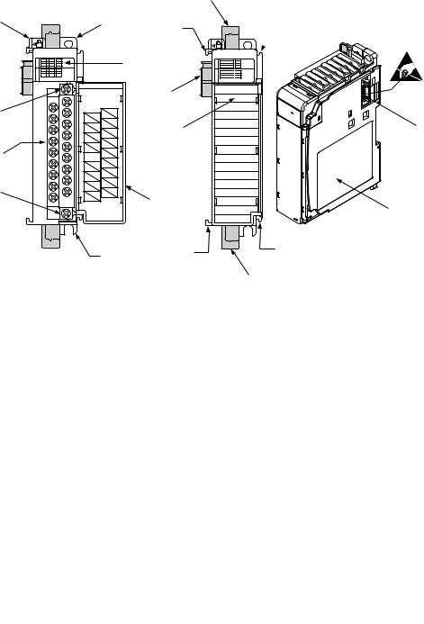
The module’s hardware features are illustrated in Figure 1. Refer to Chapter 3 on page 45 for detailed information on installation and wiring.
For information about the packaged controllers’ hardware features, see the
CompactLogix Packaged Controllers Quick Start and User Manual, publication IASIMP-QS010.
Figure 1 - Hardware Features
|
|
|
|
|
9a |
1 |
|
|
|
2a |
8a |
|
|
|
|
|
|
OUT |
0 |
2 |
|
3 |
OUT |
1 |
3 |
|
|||
IN |
A0 |
B0 |
Z0 |
|
IN |
A1 |
B1 |
Z1 |
|
||
|
|
|
|||
|
High Speed Counter |
|
|
||
|
|
|
DANGER |
6a |
|
|
|
|
|
||
5a |
|
|
Do Not Remove RTB Under Power |
|
|
|
|
Unless Area is Non-Hazardous |
|
||
|
|
|
OUT DC |
|
|
|
|
|
OUT 0 |
+5V/24V |
|
|
|
|
|
|
|
|
|
|
OUT 2 |
OUT 1 |
10 |
|
|
|
|
||
|
|
|
OUT DC |
OUT 3 |
|
|
|
|
COM |
A0+ |
|
5 |
|
|
A0- |
|
|
|
|
|
|
||
|
|
B0- |
B0+ |
|
|
|
|
|
|
|
|
|
|
|
Z0- |
Z0+ |
|
|
|
|
|
|
|
|
|
|
A1- |
A1+ |
|
|
|
|
|
|
|
5b |
|
|
B1- |
B1+ |
|
|
|
Z1+ |
|
||
|
|
|
Z1- |
|
4 |
|
|
|
|
Ensure Adjacent |
|
|
|
|
Bus Lever is Unlatched/Latched |
||
|
|
|
Before/After |
|
|
|
|
|
Removing/Inserting Module |
|
|
|
|
|
|
1769-HSC |
|
|
|
|
|
2b |
8b |
 8a
8a
0 
 2
2
1 
 3
3
A0 
 B0
B0 
 Z0
Z0
A1 
 B1
B1 
 Z1
Z1
High Speed Counter
6b
7
8b
9b |
45271 |
|
Item |
Description |
|
|
1 |
Bus lever |
|
|
2a |
Upper panel mounting tab |
|
|
2b |
Lower panel mounting tab |
|
|
3 |
Module status indicators (6 Input, 4 Output, 1 Fuse, 1 OK) |
|
|
4 |
Module door with terminal identification label |
|
|
5 |
Removable terminal block (RTB) with finger-safe cover |
|
|
5a |
RTB upper-retaining screw |
|
|
5b |
RTB lower-retaining screw |
|
|
6a |
Movable bus connector (bus interface) with female pins |
|
|
6b |
Stationary bus connector (bus interface) with male pins |
|
|
7 |
Nameplate label |
|
|
8a |
Upper tongue-and-groove slots |
|
|
8b |
Lower tongue-and-groove slots |
|
|
9a |
Upper DIN-rail latch |
|
|
9b |
Lower DIN-rail latch |
|
|
10 |
Write-on label for user identification tags |
|
|
Rockwell Automation Publication 1769-UM006E-EN-P - July 2013 |
13 |
Chapter 1 Module Overview
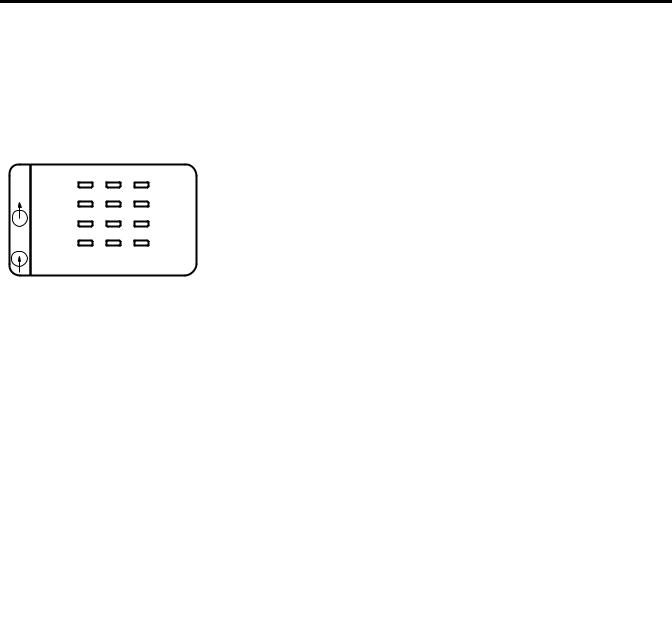
Status Indicators
OUT |
0 |
2 |
FUSE |
|
1 |
3 |
OK |
||
IN |
AO |
BO |
ZO |
|
A1 |
B1 |
Z1 |
||
|
High Speed Counter
The front panel of the 1769-HSC module has a total of 12 status indicators.
For information about the packaged controllers’ status indicators, see the
CompactLogix Packaged Controllers Quick Start and User Manual, publication IASIMP-QS010.
Table 1 - Diagnostic Indicators
|
Indicator |
Status |
Description |
|
|
|
|
|
0 OUT |
Amber |
ON/OFF logic status of output 0 |
|
|
|
|
|
1 OUT |
Amber |
ON/OFF logic status of output 1 |
|
|
|
|
|
2 OUT |
Amber |
ON/OFF logic status of output 2 |
|
|
|
|
|
3 OUT |
Amber |
ON/OFF logic status of output 3 |
|
|
|
|
|
FUSE |
Red |
Overcurrent |
|
|
|
|
45272 |
OK |
Off |
No power is applied |
|
|
|
|
|
|
Red (briefly) |
Performing self-test |
|
|
|
|
|
|
Solid green |
OK, normal operating condition |
|
|
|
|
|
|
Flashing green |
OK, module in Program or Fault mode |
|
|
|
|
|
|
Solid red or amber |
Hardware error. Cycle power to the module. If problem persists, |
|
|
|
replace the module. |
|
|
|
|
|
|
Flashing red |
Recoverable fault. Reconfigure, reset, or perform error recovery. |
|
|
|
See Non-critical versus Critical Module Errors on page 113. The |
|
|
|
OK indicator flashes red for all of the error codes in the |
|
|
|
Configuration Error Codes table on page 117. |
|
|
|
|
|
A0 |
Amber |
ON/OFF status of input A0 |
|
|
|
|
|
A1 |
Amber |
ON/OFF status of input A1 |
|
|
|
|
|
B0 |
Amber |
ON/OFF status of input B0 |
|
|
|
|
|
B1 |
Amber |
ON/OFF status of input B1 |
|
|
|
|
|
Z0 |
Amber |
ON/OFF status of input Z0 |
|
|
|
|
|
Z1 |
Amber |
ON/OFF status of input Z1 |
|
|
|
|
|
ALL ON |
Possible causes for all status indicators to be On include the following: |
|
|
|
• Bus error has occurred—controller hard fault. Cycle power. |
|
|
|
• During load upgrade of controller—normal operation. Do not cycle power during the |
|
|
|
load upgrade. |
|
|
|
• All indicators flash on briefly during powerup—normal operation. |
|
|
|
|
|
14 |
Rockwell Automation Publication 1769-UM006E-EN-P - July 2013 |

Chapter 2
Module Operation
Counter Defaults
This chapter details the operation of the 1769-HSC module. We strongly suggest that you review this information before configuring your module.
Topic |
Page |
|
|
Counter Defaults |
15 |
|
|
Module Operation Block Diagrams |
16 |
|
|
Number of Counters |
18 |
|
|
Summary of Available Counter Configurations |
18 |
|
|
Input Filtering |
20 |
|
|
Operational Mode Selection |
21 |
|
|
Input Frequency |
28 |
|
|
Counter Types |
28 |
|
|
Modifying Count Value |
29 |
|
|
Rate/Timer Functionality |
32 |
|
|
Output Control |
36 |
|
|
When the module powers up, all output array and configuration array values are set to their default values. Refer to Chapter 4 on page 65 or Appendix D on page 149 for default values. All input array values are cleared. None of the module data is retentive through a power cycle.
Power cycling the module has the following effects:
•Clears stored counts and configurations
•Clears faults and flags
•Turns outputs off
Rockwell Automation Publication 1769-UM006E-EN-P - July 2013 |
15 |
Chapter 2 Module Operation
Module Operation Block
Diagrams
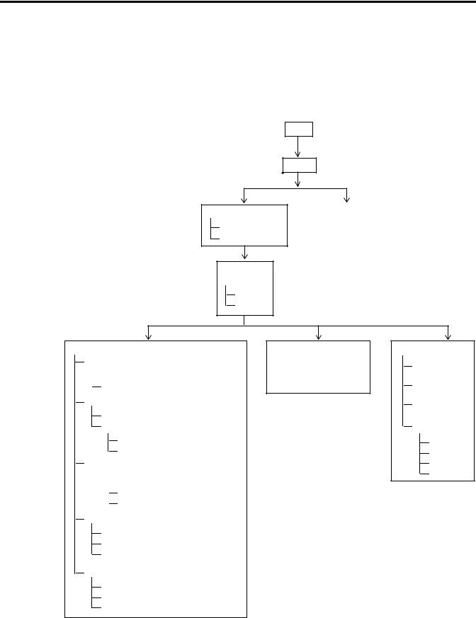
To provide an overview of the module operation, the block diagrams indicate relationships between module functions and configuration parameters.
Inputs
The following diagram illustrates how the inputs function.
Input
Filtering
Decoded |
Discrete Input State |
|
|
NumberOfCounters
Operational Mode
Pulse
Direction
DirInvert
DirInhibit
Count
Min/Max and Linear/Ring

 Overflow (ResetOvf)(1)
Underflow (ResetUdf)(1)
Store
CtrnConfig.StorageMode_0
RisingEdgeZ (reset REZ)(1)
ZInhibit
ZInvert
Enable

 CtrnEn
CtrnConfig.StorageMode_1
InputStateZn ‘gating’
Direct Write
HiLimOrDirWr
LoadDirectWrite
ToThisCounter
Preset
CtrnSoftPreset
CtrnConfig.StorageMode_2 and Rising Edge Z
Automatic PresetWarning (Preset Warning)(1)
(1) Resets.
Pulse Interval(2)
See page 32 to determine how and when to use to calculate rates.
(2)Does not apply to packaged controller.
Rate(3)
Update Time
Scalar
Hysteresis
Rate Valid
Overflow
Underflow
Preset
Direct Write
(3)Does not apply to packaged controller.
16 |
Rockwell Automation Publication 1769-UM006E-EN-P - July 2013 |
Module Operation |
Chapter 2 |
|
|
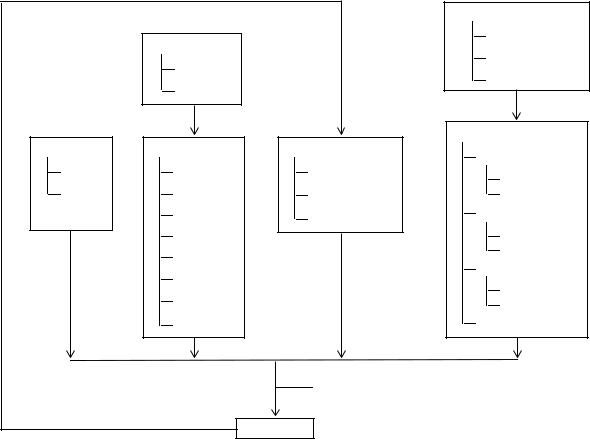
Outputs
The following diagram illustrates how the outputs function.
|
|
|
Mode |
|
Object Value |
|
Run |
|
|
Program |
|
|
Current Count |
|
|
|
|
Fault |
|
|
Current Rate |
|
|
|
|
|
|
|
|
|
Mode (Program/Fault/Run) |
Discrete |
Ranges |
Overcurrent |
Hold Last State |
|
|
|
|
On Mask |
High Limit |
Overcurrent Flags |
Program Mode |
|
|
|
|
Off Mask |
Low Limit |
OverCurrentLatchOff |
Fault Mode |
|
Type(1) |
ResetBlownFuse |
User-defined Safe State |
|
Invert |
|
Program State |
|
Counter |
|
Fault State |
|
|
Safe State Run |
|
|
Active |
|
|
|
|
Program State Run |
|
|
Output Control |
|
|
|
|
Fault State Run |
|
|
Range Enable |
|
Program to Fault Enable |
|
|
Readback (Real and Virtual) |
|
Feedback |
Output Real Only) |
|
|
|
|
||
(1)In the packaged controller, the Type parameter is fixed at Count because the rate measurement is not supported.
Rockwell Automation Publication 1769-UM006E-EN-P - July 2013 |
17 |

Chapter 2 Module Operation
Number of Counters
Summary of Available
Counter Configurations
The module has six input points: A0, B0, Z0, A1, B1, and Z1. Through these inputs, the module can function with 1, 2, 3, or 4 counters depending upon the number of counters and the operational mode configuration of the input points.
The table summarizes the input configurations available for all counters, based on the number of counters.
No. of Counters |
Counter |
Operational Mode |
Gate or Preset Functionality |
|
|
|
|
|
|
1 |
Counter |
0 |
Any |
All |
|
|
|
|
|
|
|
1 through 3 |
Not available |
|
|
|
|
|
|
2 |
Counters |
0 |
Any |
All |
|
|
|
|
|
|
|
1 |
Any |
All |
|
|
|
|
|
|
|
2 and 3 |
Not available |
|
|
|
|
|
|
3 |
Counters |
0 |
Any |
All |
|
|
|
|
|
|
|
1 |
Pulse/Internal Direction |
All |
|
|
|
|
|
|
|
2 |
Pulse/Internal Direction |
None |
|
|
|
|
|
|
|
3 |
Not available |
|
|
|
|
|
|
4 |
Counters |
0 |
Pulse/Internal Direction |
All |
|
|
|
|
|
|
|
1 |
Pulse/Internal Direction |
All |
|
|
|
|
|
|
|
2 |
Pulse/Internal Direction |
None |
|
|
|
|
|
|
|
3 |
Pulse/Internal Direction |
None |
|
|
|
|
|
18 |
Rockwell Automation Publication 1769-UM006E-EN-P - July 2013 |

Module Operation |
Chapter 2 |
|
|
The counter options and operating modes are summarized in Figure 2.
Figure 2 - Summary of Available Counters
|
AO |
|
|
|
|
|
|
|
AO |
|
|
|
|
|
|
|
|
|
|
Counter 0 |
|
Counter 2 |
|
|
Counter 0 |
|
|
Counter 2 |
|
||||||
|
|
|
|
|
|
|
|
|
|
||||||||
|
BO |
|
Any Mode |
|
Not Available |
|
BO |
|
Any Mode |
|
|
Not Available |
|
||||
|
ZO |
|
|
|
|
|
|
|
ZO |
|
|
|
|
|
|
|
|
|
A1 |
|
|
|
|
|
|
|
A1 |
|
|
|
|
|
|
|
|
|
|
Counter 1 |
|
Counter 3 |
|
|
Counter 1 |
|
|
Counter 3 |
|
||||||
|
B1 |
|
|
|
B1 |
|
|
|
|
||||||||
|
|
Not Available |
|
Not Available |
|
|
Any Mode |
|
|
Not Available |
|
||||||
|
Z1 |
|
|
|
Z1 |
|
|
|
|
||||||||
|
|
|
|
|
|
|
|
|
|
|
|
|
|
|
|
||
|
|
|
|
|
|
|
|
|
|
|
|
|
|||||
|
|
|
1 Counter(1) |
|
|
|
2 Counters(1) |
|
|||||||||
|
|
|
|
|
|
|
|
|
|
|
|
|
|
|
|
|
|
|
AO |
|
|
|
|
|
|
|
AO |
|
|
|
|
|
|
|
|
|
Counter 0 |
|
|
Counter 2 |
|
B1 |
Counter 0 |
|
|
Counter 2 |
|
|
|||||
|
BO |
|
|
|
|
|
|
|
B1 |
||||||||
|
Any Mode |
|
|
Pulse |
|
|
|
Pulse |
|
|
|
Pulse |
|
||||
|
ZO |
|
|
|
|
Internal |
|
|
ZO |
Internal |
|
|
Internal |
|
|
||
|
A1 |
|
|
|
|
|
|
|
|
|
|
|
|
|
|
|
|
|
Counter 1 |
|
|
Counter 3 |
|
|
A1 |
Counter 1 |
|
|
Counter |
|
BO |
||||
|
|
|
|
|
|
|
|
|
|
||||||||
|
|
|
Pulse |
|
|
|
|
|
|
Pulse |
|
|
|
Pulse |
|
||
|
|
|
|
Not Available |
|
|
|
|
|
|
|
|
|||||
|
Z1 |
|
Internal |
|
|
|
Z1 |
Internal |
|
|
Internal |
|
|
||||
|
|
|
|
|
|
|
|
|
|
|
|||||||
|
|
|
3 Counters(1) |
|
|
|
4 Counters(1) |
|
|||||||||
45273 |
|
|
|
|
|||||||||||||
|
(1) The number of counters is defined by the NumberOfCounters bits in word 0 of the configuration array. |
|
|||||||||||||||
Rockwell Automation Publication 1769-UM006E-EN-P - July 2013 |
19 |

Chapter 2 Module Operation
Input Filtering
In many industrial environments, high frequency noise can be inadvertently coupled to the sensor wires. The module can help reject some noise by means of
built-in filters. Inputs are filtered by means of user-selectable, low-pass filters(1) set up during module configuration.
The available nominal pulse width filters are shown in the table.
Input |
Filter |
|
|
|
|
A0, A1, B0, B1, Z0, Z1 |
5 ms, 500 s, 10 s, no filter |
|
|
(7.1 ms, 715 |
s, 18.5 s, no filter for the packaged controller) |
|
|
|
The filters are selected for each input in the Filter Selection word of the module’s configuration array.
TIP |
The input state bits (InputStateA0 through InputStateZ1) reflect the |
|
filter’s inputs, but are NOT affected by the signal inhibit or invert |
|
operations described on page 30. |
Nom Filter Settings |
|
|
Max Guaranteed Blocked Pulse Width |
Min Guaranteed Pass Pulse Width |
||||
Pulse Width |
|
Equivalent |
Pulse Width |
|
Equivalent |
Pulse Width |
|
Equivalent |
|
|
|
||||||
|
|
Frequency(1) |
|
|
Frequency(1) |
|
|
Frequency(1) |
No filter |
|
1 MHz |
N/A |
|
N/A |
250 ns |
|
2 MHz |
|
|
|
|
|
|
|
|
|
10 µs |
|
50 kHz |
7.4 µs |
|
67.5 kHz |
25 µs |
|
20 kHz |
|
|
|
|
|
|
|
|
|
500 µs |
|
1 kHz |
370 µs |
|
1.35 kHz |
1.25 ms |
|
400 Hz |
|
|
|
|
|
|
|
|
|
5 ms |
|
100 Hz |
3.7 ms |
|
135 Hz |
12.5 ms |
|
40 Hz |
|
|
|
|
|
|
|
|
|
(1)Equivalent frequency assumes a perfect 50% duty cycle and are for reference purposes only. Hence, the no-filter setting is guaranteed to pass 4 MHz even though the module’s maximum is 1 MHz. This lets the sensor and wiring to attenuate the pulse to 25% duty cycle while the module maintains pulse recognition.
Nom Filter Settings |
|
|
Max Guaranteed Blocked Pulse Width |
Min Guaranteed Pass Pulse Width |
||||
Pulse Width |
|
Equivalent |
Pulse Width |
|
Equivalent |
Pulse Width |
|
Equivalent |
|
|
|
||||||
|
|
Frequency(1) |
|
|
Frequency(1) |
|
|
Frequency(1) |
No filter |
|
250 kHz |
0.83 µs |
|
600 kHz |
2.5 µs |
|
200 kHz |
|
|
|
|
|
|
|
|
|
18.5 µs |
|
27 kHz |
12.3 µs |
|
40.5 kHz |
28.6 µs |
|
17.5 kHz |
|
|
|
|
|
|
|
|
|
715 µs |
|
700 Hz |
495 µs |
|
1.01 kHz |
1.25 ms |
|
400 Hz |
|
|
|
|
|
|
|
|
|
7.1 ms |
|
70 Hz |
4.95 ms |
|
101 Hz |
12.5 ms |
|
40 Hz |
|
|
|
|
|
|
|
|
|
(1)Equivalent frequency assumes a perfect 50% duty cycle and are for reference purposes only. Hence, the no-filter setting is guaranteed to pass 4 MHz even though the module’s maximum is 1 MHz. This lets the sensor and wiring to attenuate the pulse to 25% duty cycle while the module maintains pulse recognition.
IMPORTANT The built-in filters are simple, averaging, low-pass filters. They are designed to block noise pulses of width equal to the values presented in Table Filter Pulse Width and Frequency. Applying full amplitude, 50% duty cycle signals that are of frequency above the selected filter’s threshold frequency can result in an average value signal of sufficient amplitude to turn the input on. A transition from no input to the full amplitude, 50% duty cycle signal (or back to no signal) can result in inadvertent input transitions.
(1) Low-pass filters block frequencies above the threshold frequency.
20 |
Rockwell Automation Publication 1769-UM006E-EN-P - July 2013 |
Module Operation |
Chapter 2 |
|
|
Operational Mode
Selection
A count channel’s operational mode configuration selection determines how the A and B inputs cause a counter channel to increment or decrement. The six available mode selections are the following:
•Pulse/External Direction Input
•Pulse/Internal Direction Input
•Up and Down Pulse Input
•X1 Quadrature Encoder Input
•X2 Quadrature Encoder Input
•X4 Quadrature Encoder Input
IMPORTANT The operational mode selection is limited by the number of counters selected.
•With two counters selected, Counters 0 and 1 can be assigned any operational mode.
•With three counters selected, Counter 0 can be assigned any mode, but Counters 1 and 2 can only be configured as pulse/internal direction.
•With four counters selected, all counters must be configured for the pulse/internal direction mode.
See Figure 2 on page 19 for the operational modes available for the counters, based on the number of counters configured.
Direction Inhibit and Direction Invert Output Control Bits
These bits apply to all of the counter modes.
TIP |
When set, the Direction Inhibit bit disables any physical input from |
|
affecting count direction. |
|
When set, the Direction Invert bit changes the direction of the counter in |
|
all operational modes. |
|
When Direction Inhibit is set, then Direction Invert is the direction. |
Rockwell Automation Publication 1769-UM006E-EN-P - July 2013 |
21 |
Chapter 2 Module Operation
Pulse/External Direction Mode Selection
In this mode, the B input controls the direction of the counter, as shown in Figure 3. If the B input is low (0), the counter increments on the rising edges of input A. If the input B is high (1), the counter decrements on the rising edges of input A.
TIP |
Two Output Control bits let you modify the operation of the B input from |
|
your control program or during configuration. The Direction Inhibit bit, |
|
when set (1), disables the operation of the B input. |
|
The Direction Invert bit, when set (1), reverses the operation of the |
|
B input, but only if the Direction Inhibit bit is not set. If the Direction |
|
Inhibit bit is set, then the Direction Invert bit controls counter direction: |
|
• When the Direction Inhibit bit is set (1) and Direction Invert = 0, count |
|
direction is up (forward). |
|
• When the Direction Inhibit bit is set (1) and Direction Invert = 1, count |
|
direction is down (reversed). |
Figure 3 - Pulse/External Direction Mode (direction inhibit = 0, direction invert = 0)
|
|
|
|
|
|
|
Count Pulse |
Input A |
|
|
|
|
|
|
|
||
|
|
|
|
|
|
|
Direction Control |
|
|
|
|
|
|
|
|||
|
|
|
|
|
|
|
|
|
|
Encoder or Sensor |
Input B |
||||||
|
|
|
|
|
|
|
|
Input Z |
|
|
|
|
|
|
|
|
|
|
|
|
|
|
|
|
|
|
|
Sensor or Switch |
|
|
|||||
Count Pulse
Direction Control
High = Decrement
Low = Increment
Count
22 |
Rockwell Automation Publication 1769-UM006E-EN-P - July 2013 |

Module Operation |
Chapter 2 |
|
|
Table 2 - Pulse External Direction Counting
Direction |
Direction |
Input A (count) |
Input B (direction) |
Change in |
Inhibit Bit |
Invert Bit |
|
|
Count Value |
|
|
|
|
|
0 |
0 |
|
0 or open |
1 |
|
|
|
|
|
|
|
|
1 |
-1 |
|
|
|
|
|
|
|
0, 1, |
Don’t care |
0 |
|
|
|
|
|
0 |
1 |
|
0 or open |
-1 |
|
|
|
|
|
|
|
|
1 |
1 |
|
|
|
|
|
|
|
0, 1, |
Don’t care |
0 |
|
|
|
|
|
1 |
0 |
|
0 or open |
1 |
|
|
|
|
|
|
|
|
1 |
1 |
|
|
|
|
|
|
|
0, 1, |
Don’t care |
0 |
|
|
|
|
|
1 |
1 |
|
0 or open |
-1 |
|
|
|
|
|
|
|
|
1 |
-1 |
|
|
|
|
|
|
|
0, 1, |
Don’t care |
0 |
|
|
|
|
|
See Direction Inhibit and Direction Invert Output Control Bits on page 21 for more information.
Pulse/Internal Direction Mode Selection
When the Pulse/Internal Direction mode is selected, the status of the Direction
Invert bit, as controlled by the user program, determines the direction of the counter. The counter increments on the rising edge of the module’s A input when the Direction Invert bit is reset (0). The counter decrements on the rising edge of the A input when the Direction Invert bit is set (1).
Table 3 - Pulse Internal Direction Counting - Counters 0 and 1
Direction |
Direction |
Input A (count) |
Input B |
Change in Count |
Inhibit Bit |
Invert Bit |
|
|
Value |
|
|
|
|
|
Don’t care |
0 |
|
Don’t care |
1 |
|
|
|
|
|
|
|
0, 1, |
Don’t care |
0 |
|
|
|
|
|
Don’t care |
1 |
|
Don’t care |
-1 |
|
|
|
|
|
|
|
0, 1, |
Don’t care |
0 |
|
|
|
|
|
Table 4 - Pulse Internal Direction Counting - Counters 2 and 3
Direction |
Direction |
Input A |
Input B (count) |
Change in Count |
Inhibit Bit |
Invert Bit |
|
|
Value |
|
|
|
|
|
Don’t care |
0 |
Don’t care |
|
1 |
|
|
|
|
|
|
|
Don’t care |
0, 1, |
0 |
|
|
|
|
|
Don’t care |
1 |
Don’t care |
|
-1 |
|
|
|
|
|
|
|
Don’t care |
0, 1, |
0 |
|
|
|
|
|
Rockwell Automation Publication 1769-UM006E-EN-P - July 2013 |
23 |
Chapter 2 Module Operation
Up and Down Pulses Mode Selection
In this mode, the counter channel increments on the rising edge of pulses applied to input A and decrements on the rising edge of pulses applied to input B. When set, the Direction Inhibit bit causes both A and B to increment. When set, the
Direction Invert bit causes B to increment and A to decrement. When the Direction Invert and Direction Inhibit bits are both set, both A and B decrement.
TIP |
When both inputs transition simultaneously or near simultaneously, the |
|
net result is no change to the count value. |
Figure 4 - Up and Down Pulse Mode (direction inhibit = 0, direction invert = 0)
|
|
|
|
|
|
|
|
Input A |
|
|
|
|
|
|
|
|
|
|
|
|
|
|
|
Increment Pulse |
||
|
|
|
|
|
|
|
||
|
|
|
|
|
|
(count up) |
|
|
|
|
Incrementing Encoder |
Input B |
|||||
|
|
|
|
|||||
|
|
|
|
or Sensor |
|
|
|
|
|
|
|
|
|
|
|
|
Input Z |
|
|
|
|
|
|
|
|
|
|
|
|
|
|
|
|
|
|
|
|
|
|
|
|
|
|
|
|
|
|
|
|
|
Decrement Pulse |
|
Module |
|
|
|
|
|
|
(count down) |
||
|
|
|
|
|
|
|
||
Decrementing Encoder or |
|
|||||||
|
|
|
||||||
|
|
|
|
Sensor |
|
|
|
|
Increment Pulse
(Input A)
Decrement Pulse
(Input B)
Count
24 |
Rockwell Automation Publication 1769-UM006E-EN-P - July 2013 |

Module Operation |
Chapter 2 |
|
|
Table 5 - Up and Down Counting
Direction |
Direction |
Input A (count) |
Input B (direction) |
Change in |
Inhibit Bit |
Invert Bit |
|
|
Count Value |
|
|
|
|
|
0 |
0 |
|
0, 1, |
1 |
|
|
|
|
|
|
|
0, 1, |
|
-1 |
|
|
|
|
|
|
|
|
|
0 |
|
|
|
|
|
0 |
1 |
|
0, 1, |
-1 |
|
|
|
|
|
|
|
0, 1, |
|
1 |
|
|
|
|
|
|
|
|
|
0 |
|
|
|
|
|
1 |
0 |
|
0, 1, |
1 |
|
|
|
|
|
|
|
0, 1, |
|
1 |
|
|
|
|
|
|
|
|
|
0 |
|
|
|
|
|
1 |
1 |
|
0, 1, |
-1 |
|
|
|
|
|
|
|
0, 1, |
|
-1 |
|
|
|
|
|
|
|
|
|
0 |
|
|
|
|
|
X1 Quadrature Encoder Mode Selection
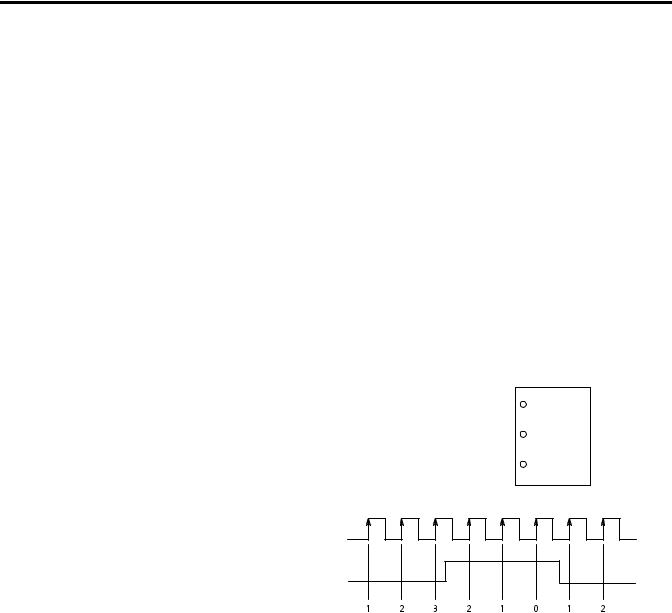
In this mode, when a quadrature encoder is attached to inputs A and B, the count direction is determined by the phase relation of inputs A and B. If A leads B, the counter increments. If B leads A, the counter decrements. In other words, when B is low, the count increments on the rising edge of input A and decrements on the falling edge of input A. If B is high, all rising transitions on input A are ignored.
The counter changes value only on one edge of input A as shown in Figure 5.
TIP |
When both A and B transition at the same time, instead of in the defined |
|
90° phase separation, the quadrature signal is invalid. |
For more information see Direction Inhibit and Direction Invert Output
Control Bits on page 21 and their effect on Quadrature signals on page 27.
Rockwell Automation Publication 1769-UM006E-EN-P - July 2013 |
25 |
Chapter 2 Module Operation
Figure 5 - Quadrature Encoder Modes (direction inhibit = 0, direction invert = 0)
|
A |
Input A |
|
|
|
|
B |
Input B |
|
|
|
Quadrature |
Z |
Input Z |
|
||
Encoder |
|
|
Forward Rotation |
|
Reverse Rotation |
A
B
X1 Count
X2 Count
X4 Count
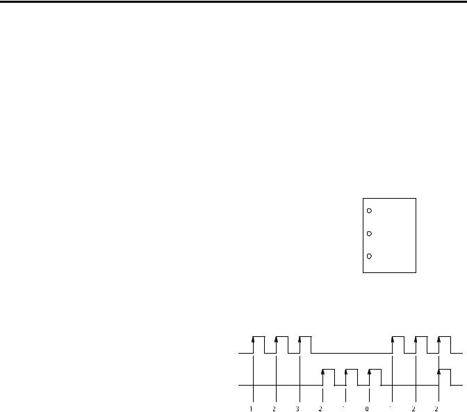
X2 Quadrature Encoder Mode Selection
The X2 Quadrature Encoder mode operates much like the X1 Quadrature
Encoder except that the resolution is doubled as shown in Figure 5 on page 26.
X4 Quadrature Encoder Mode Selection
The X4 Quadrature Encoder mode operates much like the X1 Quadrature
Encoder except that the resolution is quadrupled, as shown in Figure 5 on page 26.
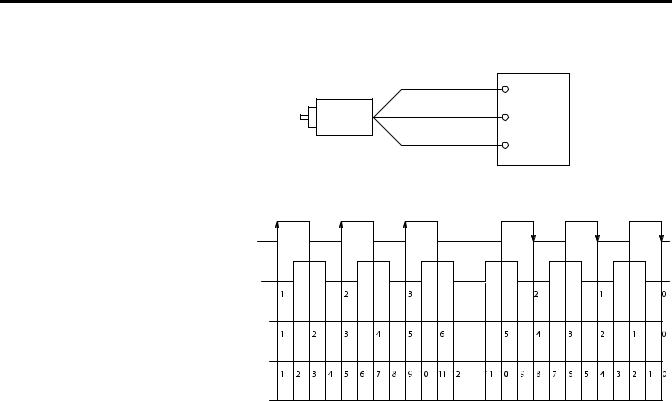
Figure 6 shows how Direction Inhibit and Direction Invert affect the counter.
26 |
Rockwell Automation Publication 1769-UM006E-EN-P - July 2013 |

Module Operation |
Chapter 2 |
|
|
Figure 6 - Operation Using Various Direction Inhibit and Direction Invert Settings
|
A |
Input A |
|
|
|
Quadrature |
B |
Input B |
Encoder |
|
|
Z |
|
|
|
Input Z |
|
|
|
|
Forward Rotation |
|
Reverse Rotation |
A |
|
B |
|
DirectionInhibit = 0; DirectionInvert = 0 |
|
X1 Count Pulse |
|
X2 Count Pulse |
|
X4 Count Pulse |
|
DirectionInhibit = 0; DirectionInvert = 1 |
|
X1 Count Pulse |
|
X2 Count Pulse |
|
X4 Count Pulse |
|
DirectionInhibit = 1; DirectionInvert = 0 |
|
X1 Count Pulse |
|
X2 Count Pulse |
|
X4 Count Pulse |
|
DirectionInhibit = 1; DirectionInvert = 1 |
|
X1 Count Pulse |
|
X2 Count Pulse |
|
X4 Count Pulse |
|
Rockwell Automation Publication 1769-UM006E-EN-P - July 2013 |
27 |
Chapter 2 Module Operation
Input Frequency
Counter Types
Maximum input frequency is determined by the input configuration as shown in the table.
Input Configuration |
Input Frequency |
Input Frequency |
|
1769-HSC Module |
Packaged Controller |
|
|
|
X4 Quadrature encoder |
250 kHz |
250 kHz |
|
|
|
X2 Quadrature encoder |
500 kHz |
250 kHz |
|
|
|
All other configurations |
1 MHz |
250 kHz |
|
|
|
Each of the four possible counters can be configured to stop counting and set a flag at its limits (linear counter) or to rollover and set a flag at its limits (ring counter). A counter’s limits are programmed by the CtrnMaxCount and
CtrnMinCount words in the module’s configuration array. Both types are described below.
Linear Counter
Figure 7 illustrates linear counter operation. In linear operation, the current count
(Ctr[n].CurrentCount) value remains between, or equal to, the user-programmed minimum count (CtrnMinCount) and maximum count
(CtrnMaxCount) values. If the Ctr[n].CurrentCount value goes above (>) or below (<) these values, the counter stops counting, and an overflow/underflow bit is set. The overflow/underflow bits can be reset using the
CtrnResetCounterOverflow and CtrnResetCounterUnderflow bits.
Figure 7 - Linear Counter Diagram
Minimum Count Value |
0 |
Maximum Count Value |
Count Up
|
|
Counter Value |
||||
|
|
|
|
|
|
|
Underflow and Hold |
|
|
Count Down |
|
|
|
|
||||||
|
|
|
|
|||
|
|
Overflow and Hold |
||||
Pulses are not accumulated in an overflow/underflow state. The counter begins counting again when pulses are applied in the proper direction. For example, if you exceed the maximum by 1000 counts, you do not need to apply 1000 counts in the opposite direction before the counter begins counting down. The first pulse in the opposite direction decrements the counter.
28 |
Rockwell Automation Publication 1769-UM006E-EN-P - July 2013 |
Module Operation |
Chapter 2 |
|
|
Modifying Count Value
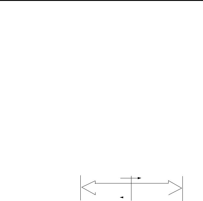
Ring Counter
Figure 8 demonstrates ring counter operation. In ring counter operation, the current count (Ctr[n].CurrentCount) value changes between user-programmable minimum count (CtrnMinCount) and maximum count (CtrnMaxCount) values. If, when counting up, the counter reaches the CtrnMaxCount value, it rolls over to the CtrnMinCount value upon receiving the next count and sets the overflow bit. If, when counting down, the counter reaches the CtrnMinCount value, it rolls under to the CtrnMaxCount value upon receiving the next count and sets the underflow bit. These bits can be reset using the CtrnResetCounterOverflow and CtrnResetCounterUnderflow bits.
Figure 8 - Ring Counter Diagram
Maximum Count Value |
Minimum Count Value |
Rollover
Count Down |
Count Up |
|
The count value (Ctr[n].CurrentCount) can be stored, reset, or preset using the
Z-input, CtrReset bit in the configuration array, control bits in the output array, or overwritten using a Direct Write command.
Table 6 - Available Z Functions
Setting |
For function |
|
|
Store(1) |
On rising edge of Z, store count in the Stored Count input word |
Hold |
While Z = 1, hold counter at its current value |
|
|
Preset/Reset |
On rising edge of Z, preset the count value to the value in the preset word |
|
|
(1)If both a store and preset function are configured, the stored count is captured before the preset operation takes place.
IMPORTANT Because only the Z-inputs are used for external gating and presetting, these functions are not available for Counters 2 and 3, which do not have Z-inputs. All options are always available for Counters 0 and 1, regardless of input operational mode.
Rockwell Automation Publication 1769-UM006E-EN-P - July 2013 |
29 |

Chapter 2 Module Operation
Counter Enable/Disable
The counter can be enabled or disabled using the CtrnEn control bit. Be aware that disabling the counter does not inhibit any current count loading functions
(for example, preset or direct write) or any Z function.
Z Input Functions
There are three Z input functions: store, gate, and Z preset.
Store
The Z-input can be used to capture the current count value even when the counter is counting at full 1 MHz speed.
Gate
The Z-inputs can be used to gate (hold) the counter at its current value regardless of incoming A or B inputs. A gating function is typically one that lets pulses reach the counter (gate open) or not (gate closed).
Z Preset
Preset can be programmed to occur based on the actions of the Z-input signal.
Inhibit and Invert
The Z-input signals can be inverted and/or inhibited, depending on the user configuration of the CtrnZInvert and CtrnZInhibit output control bits. If the signal is inhibited, the invert bit is the Z signal for the actions described above.
For an explanation of those bits, see Z Inv - Z Invert (CtrnZInvert) on page 93 and Z Inh - Z Inhibit (CtrnZInhibit) on page 93.
Direct Write
You can arbitrarily change the current count value (Ctr[n].CurrentCount) to the direct write control value (Range12To15[n].HiLimOrDirWr). This ability applies to ranges 12…15. The direct write value takes effect when the Load Direct Write bit (Range12To15[n].LoadDirectWrite) transitions from 0 to 1.
If you attempt to preset and load direct write to a counter at the same time, only the preset (CtrnPreset) will take effect.
30 |
Rockwell Automation Publication 1769-UM006E-EN-P - July 2013 |
Loading...