


 Loading...
User Manual
Compact I/O ASCII Module
Catalog Numbers 1769-ASCII
Important User Information
Read this document and the documents listed in the additional resources section about installation, configuration, and operation of this equipment before you install, configure, operate, or maintain this product. Users are required to familiarize themselves with installation and wiring instructions in addition to requirements of all applicable codes, laws, and standards.
Activities including installation, adjustments, putting into service, use, assembly, disassembly, and maintenance are required to be carried out by suitably trained personnel in accordance with applicable code of practice.
If this equipment is used in a manner not specified by the manufacturer, the protection provided by the equipment may be impaired.
In no event will Rockwell Automation, Inc. be responsible or liable for indirect or consequential damages resulting from the use or application of this equipment.
The examples and diagrams in this manual are included solely for illustrative purposes. Because of the many variables and requirements associated with any particular installation, Rockwell Automation, Inc. cannot assume responsibility or liability for actual use based on the examples and diagrams.
No patent liability is assumed by Rockwell Automation, Inc. with respect to use of information, circuits, equipment, or software described in this manual.
Reproduction of the contents of this manual, in whole or in part, without written permission of Rockwell Automation, Inc., is prohibited.
Throughout this manual, when necessary, we use notes to make you aware of safety considerations.
WARNING: Identifies information about practices or circumstances that can cause an explosion in a hazardous environment, which may lead to personal injury or death, property damage, or economic loss.
ATTENTION: Identifies information about practices or circumstances that can lead to personal injury or death, property damage, or economic loss. Attentions help you identify a hazard, avoid a hazard, and recognize the consequence.
IMPORTANT Identifies information that is critical for successful application and understanding of the product.
Labels may also be on or inside the equipment to provide specific precautions.
SHOCK HAZARD: Labels may be on or inside the equipment, for example, a drive or motor, to alert people that dangerous voltage may be present.
BURN HAZARD: Labels may be on or inside the equipment, for example, a drive or motor, to alert people that surfaces may reach dangerous temperatures.
ARC FLASH HAZARD: Labels may be on or inside the equipment, for example, a motor control center, to alert people to potential Arc Flash. Arc Flash will cause severe injury or death. Wear proper Personal Protective Equipment (PPE). Follow ALL Regulatory requirements for safe work practices and for Personal Protective Equipment (PPE).
Allen-Bradley, Rockwell Software, Rockwell Automation, Compact I/O, CompactLogix, Logix5000, MicroLogix, RSLogix, Studio 5000 Logix Designer, and Studio 5000 are trademarks of Rockwell Automation, Inc.
Trademarks not belonging to Rockwell Automation are property of their respective companies.

Summary of Changes
New and Updated
Information
This manual contains new and updated information. Changes throughout this revision are marked by change bars, as shown to the right of this paragraph.
This table contains the changes made to this revision.
Topic |
Page |
|
|
Rearranged content and updated warnings and attentions. |
Throughout |
|
|
Updated configuration to include the CompactLogix™ 5370 L3 controller, |
7 |
provided link to the Knowledgebase Technote # 64203. |
|
|
|
Added information about the Studio 5000™ environment. |
7 |
|
|
Updated Additional Resources. |
8 |
|
|
Updated configuration examples. |
21 |
|
|
Updated I/O Memory Mapping to include the new tag structures. |
71 |
|
|
Added the Generic Module appendix. |
87 |
|
|
Added Electronic Keying appendix. |
105 |
|
|
Updated Technical Support links, website addresses, and phone numbers. |
BackCover |
|
|
Rockwell Automation Publication 1769-UM012B-EN-P - January 2014 |
3 |

Summary of Changes
Notes:
4 |
Rockwell Automation Publication 1769-UM012B-EN-P - January 2014 |

|
Table of Contents |
|
Preface |
Studio 5000 Environment . . . . . . . . . . . . . . . . . . . . . . . . . . . . . . . . . . . . . . . . . |
. 7 |
|
Additional Resources . . . . . . . . . . . . . . . . . . . . . . . . . . . . . . . . . . . . . . . . . . . . . . |
. 8 |
|
Example Programs . . . . . . . . . . . . . . . . . . . . . . . . . . . . . . . . . . . . . . . . . . . . . . . . |
. 8 |
|
Chapter 1 |
|
Compact I/O ASCII Module |
About the Module . . . . . . . . . . . . . . . . . . . . . . . . . . . . . . . . . . . . . . . . . . . . . . . . |
. 9 |
|
Environment and Enclosure. . . . . . . . . . . . . . . . . . . . . . . . . . . . . . . . . . . . . . . |
10 |
|
North American Hazardous Location Approval . . . . . . . . . . . . . . . . . . . . |
11 |
|
European Hazardous Location Approval . . . . . . . . . . . . . . . . . . . . . . . . . . . |
12 |
|
Install the Module. . . . . . . . . . . . . . . . . . . . . . . . . . . . . . . . . . . . . . . . . . . . . . . . |
13 |
|
Assemble the System . . . . . . . . . . . . . . . . . . . . . . . . . . . . . . . . . . . . . . . . . . . . . |
14 |
|
Minimum Space. . . . . . . . . . . . . . . . . . . . . . . . . . . . . . . . . . . . . . . . . . . . . . |
15 |
|
Panel Mount . . . . . . . . . . . . . . . . . . . . . . . . . . . . . . . . . . . . . . . . . . . . . . . . . |
15 |
|
DIN Rail Mount . . . . . . . . . . . . . . . . . . . . . . . . . . . . . . . . . . . . . . . . . . . . . |
16 |
|
Replace a Module. . . . . . . . . . . . . . . . . . . . . . . . . . . . . . . . . . . . . . . . . . . . . |
17 |
|
Ground the Module . . . . . . . . . . . . . . . . . . . . . . . . . . . . . . . . . . . . . . . . . . . . . . |
17 |
|
Connect the D-sub Connector Pins . . . . . . . . . . . . . . . . . . . . . . . . . . . . . . . |
18 |
|
Chapter 2 |
|
Configure the 1769-ASCII Module |
Configure the 1769-ASCII Module . . . . . . . . . . . . . . . . . . . . . . . . . . . . . . . |
21 |
|
Module Definition Dialog Box . . . . . . . . . . . . . . . . . . . . . . . . . . . . . . . . |
24 |
|
Controller-scoped Tags . . . . . . . . . . . . . . . . . . . . . . . . . . . . . . . . . . . . . . . |
32 |
|
Data Types . . . . . . . . . . . . . . . . . . . . . . . . . . . . . . . . . . . . . . . . . . . . . . . . . . |
32 |
|
Connect to Channel 0 of the Module in Alternating Mode . . . . . . . . . . |
34 |
|
Ladder Logic Example . . . . . . . . . . . . . . . . . . . . . . . . . . . . . . . . . . . . . . . . |
35 |
|
Configure the Module Properties . . . . . . . . . . . . . . . . . . . . . . . . . . . . . . |
38 |
|
Connect to Both Channels of the Module in Alternating Mode. . . . . . |
41 |
|
Ladder Logic Example . . . . . . . . . . . . . . . . . . . . . . . . . . . . . . . . . . . . . . . . |
42 |
|
Connect to Both Channels of the 1769-ASCII Module in Simultaneous |
|
|
Mode . . . . . . . . . . . . . . . . . . . . . . . . . . . . . . . . . . . . . . . . . . . . . . . . . . . . . . . . . . . |
49 |
|
Ladder Logic Example . . . . . . . . . . . . . . . . . . . . . . . . . . . . . . . . . . . . . . . . |
50 |
|
Configure the Module for Use with a MicroLogix Controller . . . . . . . . |
59 |
|
Programming Example: MicroLogix 1500 Controller . . . . . . . . . . . . . . . |
62 |
|
Chapter 3 |
|
I/O Memory Mapping |
ASCII Module Behavior when not in Run Mode . . . . . . . . . . . . . . . . . . . |
71 |
|
Alternate Mode (one channel at a time) Output File . . . . . . . . . . . . . . . . |
72 |
|
Alternate Mode (one channel at a time) Input File . . . . . . . . . . . . . . . . . . |
73 |
|
Simultaneous Mode |
|
|
(two channels) Input File . . . . . . . . . . . . . . . . . . . . . . . . . . . . . . . . . . . . . . . . . |
74 |
|
Simultaneous Mode (two channels) Output File . . . . . . . . . . . . . . . . . . . . |
75 |
|
Status Descriptions . . . . . . . . . . . . . . . . . . . . . . . . . . . . . . . . . . . . . . . . . . . |
76 |
|
Configuration File . . . . . . . . . . . . . . . . . . . . . . . . . . . . . . . . . . . . . . . . . . . . . . . |
77 |
|
Configuration File Parameter Operation . . . . . . . . . . . . . . . . . . . . . . . . . . . |
79 |
Rockwell Automation Publication 1769-UM012B-EN-P - January 2014 |
5 |

Table of Contents
Data Buffer Mode . . . . . . . . . . . . . . . . . . . . . . . . . . . . . . . . . . . . . . . . . . . . 79
Set Up the Data Frame Format . . . . . . . . . . . . . . . . . . . . . . . . . . . . . . . . 79
Receive Delimiter Mode. . . . . . . . . . . . . . . . . . . . . . . . . . . . . . . . . . . . . . . 79
Set Up the Receive Delimiters . . . . . . . . . . . . . . . . . . . . . . . . . . . . . . . . . 80
Set Up the Transmit Delimiter . . . . . . . . . . . . . . . . . . . . . . . . . . . . . . . . 81
Set Up the Receive Character Buffer Length . . . . . . . . . . . . . . . . . . . . 81
Set Up the Transmit Character Buffer Length . . . . . . . . . . . . . . . . . . 82
Receive Data Padding . . . . . . . . . . . . . . . . . . . . . . . . . . . . . . . . . . . . . . . . . 82
Byte Swap Mode. . . . . . . . . . . . . . . . . . . . . . . . . . . . . . . . . . . . . . . . . . . . . . 83
Transmit Serial ASCII Data . . . . . . . . . . . . . . . . . . . . . . . . . . . . . . . . . . . 83
Receive ASCII Serial Data. . . . . . . . . . . . . . . . . . . . . . . . . . . . . . . . . . . . . 83
Receive Timeout. . . . . . . . . . . . . . . . . . . . . . . . . . . . . . . . . . . . . . . . . . . . . . 84
How to Send Data from the 1769-ASCII Module. . . . . . . . . . . . . . . . . . . 84
How to Receive Serial Data from the 1769-ASCII Module. . . . . . . . . . . 85
Master/Slave Handshake. . . . . . . . . . . . . . . . . . . . . . . . . . . . . . . . . . . . . . . . . . 85
Appendix A
Configure the 1769-ASCII Module as a Generic Module . . . . . . . . . . . . .87
Appendix B
Status Indicators . . . . . . . . . . . . . . . . . . . . . . . . . . . . . . . . . . . . . . . . . . . . . . . . . .95
Appendix C
Error Codes. . . . . . . . . . . . . . . . . . . . . . . . . . . . . . . . . . . . . . . . . . . . . . . . . . . . . . . . .
Configuration Errors . . . . . . . . . . . . . . . . . . . . . . . . . . . . . . . . . . . . . . . . . . . . . 97
Logix Designer Example Report . . . . . . . . . . . . . . . . . . . . . . . . . . . . . . . . . . 100
RSLogix 500 Error Report Example . . . . . . . . . . . . . . . . . . . . . . . . . . . . . . . 102
Appendix D
ASCII Conversion Tables. . . . . . . . . . . . . . . . . . . . . . . . . . . . . . . . . . . . . . . . 103
Appendix E
Using Electronic Keying . . . . . . . . . . . . . . . . . . . . . . . . . . . . . . . . . . . . . . . . . 105
Electronic Keying . . . . . . . . . . . . . . . . . . . . . . . . . . . . . . . . . . . . . . . . . . . . . . . 105
Exact Match . . . . . . . . . . . . . . . . . . . . . . . . . . . . . . . . . . . . . . . . . . . . . . . . . . . . 106
Compatible Keying . . . . . . . . . . . . . . . . . . . . . . . . . . . . . . . . . . . . . . . . . . . . . . 107
Disabled Keying . . . . . . . . . . . . . . . . . . . . . . . . . . . . . . . . . . . . . . . . . . . . . . . . . 109
|
Appendix F |
|
History of Changes |
1769-UM012B-EN-P September 2013. . . . . . . . . . . . . . . . . . . . . . . . . . . . |
113 |
Index |
|
|
6 |
Rockwell Automation Publication 1769-UM012B-EN-P - January 2014 |
Preface
This manual describes how to install, configure, and troubleshoot your Compact I/O™ 1769-ASCII module. You must be able to use RSLogix™ software and the Studio 5000 Logix Designer™ application to configure this module.
The 1769-ASCII module, a general-purpose two-channel ASCII interface, provides a flexible network interface to a wide variety of RS-232, RS-485, and RS-422 ASCII devices.
The 1769-ASCII module provides two independent channels of the ASCII device interface to the 1769 Compact I/O system. Each serial channel is fully isolated from the backplane and from each other.
Each channel provides three different media to interface with a serial device and are automatically selected by making the correct connections to that channel’s 9-pin D-sub connector. The actual media selected is transparent to the 1769-ASCII module.
IMPORTANT You can use the 1769-ASCII module with the following controllers:
•CompactLogix 5370 L3 and L2
•1769-L2x and 1769-L3x
•1768-L4x
•MicroLogix™ 1500
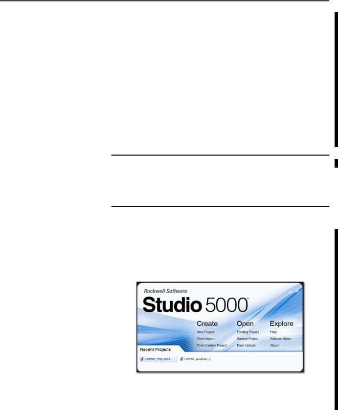
Studio 5000 Environment |
The Studio 5000 Engineering and Design Environment combines engineering |
|
and design elements into a common environment. The first element in the Studio |
|
5000 environment is the Logix Designer application. The Logix Designer |
|
application is the rebranding of RSLogix 5000 software and will continue to be |
|
the product to program Logix5000™ controllers for discrete, process, batch, |
|
motion, safety, and drive-based solutions. |
The Studio 5000 environment is the foundation for the future of Rockwell Automation® engineering design tools and capabilities. It is the one place for design engineers to develop all of the elements of their control system.
TIP |
You use RSLogix500™ software to configure the 1769-ASCII module with a |
|
|
MicroLogix1500 controller. |
|
|
|
|
Rockwell Automation Publication 1769-UM012B-EN-P - January 2014 |
7 |

Preface
Additional Resources
Example Programs
These documents contain additional information concerning related products from Rockwell Automation.
Resource |
Description |
|
|
CompactLogix 5370 L3 Controllers, Revision 20 |
Describes enhancements, known anomalies, and |
Release Notes 1769-RN020 |
restrictions for CompactLogix 5370 L3 controllers, |
|
firmware revisions 20.011…20.013 |
|
|
Compact I/O DeviceNet Adapter User Manual, |
Provides details regarding the installation, configuration, |
publication 1769-UM001 |
and operation of DeviceNet adapters. |
|
|
Logix5000 Controllers ASCII Strings Programming |
Provides details on how to manipulate ASCII strings in |
Manual, publication 1756-PM013 |
Logix5000 controllers. |
|
|
Compact I/O DeviceNet Scanner Module User Manual, |
Provides details regarding the installation, configuration, |
publication 1769-UM009 |
and operation of DeviceNet scanners. |
|
|
1768 CompactLogix L4x Controllers User Manual, |
Provides details regarding the installation, configuration, |
publication 1768-UM001 |
and operation of the 1768 CompactLogix Controllers, |
|
catalog numbers: 1768-L43, 1768-L45, 1768-L45, |
|
1768-L45S. |
|
|
CompactLogix L2x User Manual, |
Provides details regarding the installation, configuration, |
publication 1769-UM007 |
and operation of the 1768 CompactLogix Controllers, |
|
catalog numbers: 1769-L20, 1769-L30. |
|
|
CompactLogix L3x User Manual, publication |
Provides details regarding the installation, configuration, |
1769-UM011 |
and operation of the 1768 CompactLogix Controllers, |
|
catalog numbers: 1769-L31, 1769-L32C, 1769-L32E, |
|
1769-L35CR, 1769-L35E. |
|
|
Industrial Automation Wiring and Grounding |
Provides general guidelines for installing a Rockwell |
Guidelines, publication 1770-4.1 |
Automation industrial system. |
|
|
Product Certifications website, |
Provides declarations of conformity, certificates, and other |
http://www.ab.com |
certification details. |
|
|
You can view or download publications at http://www.rockwellautomation.com/literature/. To order paper copies of technical documentation, contact your local Allen-Bradley distributor or Rockwell Automation sales representative.
To access these Logix Designer programs, see the Knowledgebase Technote # 64203 at https://rockwellautomation.custhelp.com/app/answers/detail/a_id/ 64203.
8 |
Rockwell Automation Publication 1769-UM012B-EN-P - January 2014 |
Chapter 1
Compact I/O ASCII Module
About the Module
The 1769-ASCII module provides a flexible network interface to a wide variety of RS-232, RS-485, and RS-422 ASCII devices.
Topic |
Page |
|
|
About the Module |
9 |
|
|
Environment and Enclosure |
10 |
|
|
North American Hazardous Location Approval |
11 |
|
|
European Hazardous Location Approval |
12 |
|
|
Install the Module |
13 |
|
|
Assemble the System |
14 |
|
|
Ground the Module |
17 |
|
|
Connect the D-sub Connector Pins |
18 |
|
|
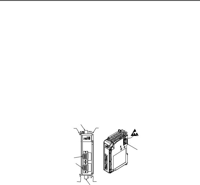
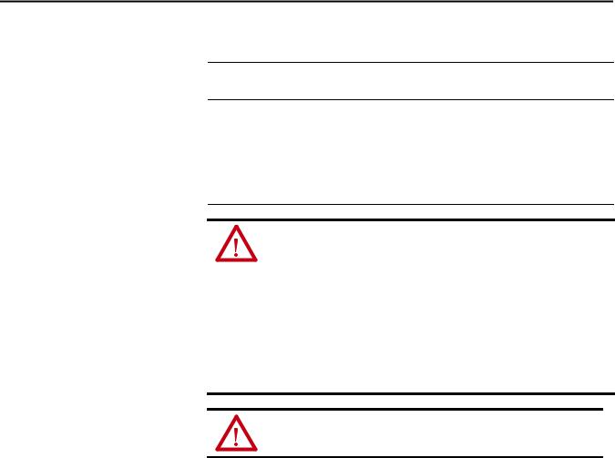
The module provides the communication connections to the ASCII device.
1a
2a |
2a |
|
4 |
3a |
|
3b |
|
2b |
2b |
|
1b |
Item |
Description |
|
|
1a |
Upper DIN rail latch |
|
|
1b |
Lower DIN rail latch |
|
|
2a |
Upper tongue-and-groove slots |
|
|
2b |
Lower tongue-and-groove slots |
|
|
3a |
Channel 0 isolated ASCII connector |
|
|
3b |
Channel 1 isolated ASCII connector |
|
|
4 |
Stationary bus connector with male pins |
|
|
Rockwell Automation Publication 1769-UM012B-EN-P - January 2014 |
9 |
Chapter 1 Compact I/O ASCII Module
Environment and Enclosure
WARNING: This equipment is intended for use in a Pollution Degree 2 industrial environment, in overvoltage Category II applications (as defined in IEC publication 60664-1), at altitudes up to 2000 meters (6562 ft) without derating.
This equipment is considered Group 1, Class A industrial equipment according to IEC/CISPR Publication 11. Without appropriate precautions, there may be potential difficulties ensuring electromagnetic compatibility in other environments due to conducted as well as radiated disturbance.
This equipment is supplied as open-type equipment. It must be mounted within an enclosure that is suitably designed for those specific environmental conditions that will be present and appropriately designed to prevent personal injury resulting from accessibility to live parts. The enclosure must have suitable flame-retardant properties to prevent or minimize the spread of flame, complying with a flame spread rating of 5VA, V2, V1, V0 (or equivalent) if nonmetallic. The interior of the enclosure must be accessible only by the use of a tool. Subsequent sections of this publication may contain additional information regarding specific enclosure type ratings that are required to comply with certain product safety certifications. In addition to this publication, see the following:
•Industrial Automation Wiring and Grounding Guidelines, Allen-Bradley publication 1770-4.1, for additional installation requirements
•NEMA Standards publication 250 and IEC publication 60529, as applicable, for explanations of the degrees of protection provided by different types of enclosure
10 |
Rockwell Automation Publication 1769-UM012B-EN-P - January 2014 |
Compact I/O ASCII Module Chapter 1
North American Hazardous Location Approval
The following information applies when operating this |
Informations sur l’utilisation de cet équipement en |
|||
equipment in hazardous locations. |
environnements dangereux. |
|||
|
|
|
||
Products marked `CL I, DIV 2, GP A, B, C, D’ are |
Les produits marqués `CL I, DIV 2, GP A, B, C, D’ ne |
|||
conviennent qu'à une utilisation en environnements de |
||||
suitable for use in Class I Division 2 Groups A, B, C, D, |
||||
Classe I Division 2 Groupes A, B, C, D dangereux et non |
||||
Hazardous Locations and nonhazardous locations |
||||
dangereux. Chaque produit est livré avec des |
||||
only. Each product is supplied with markings on the |
||||
marquages sur sa plaque d'identification qui indiquent |
||||
rating nameplate indicating the hazardous location |
||||
le code de température pour les environnements |
||||
temperature code. When combining products |
||||
dangereux. Lorsque plusieurs produits sont combinés |
||||
within a system, the most adverse temperature |
||||
dans un système, le code de température le plus |
||||
code (lowest `T’ number) may be used to help |
||||
défavorable (code de température le plus faible) peut |
||||
determine the overall temperature code of the |
||||
être utilisé pour déterminer le code de température |
||||
system. Combinations of equipment in your system |
||||
global du système. Les combinaisons d'équipements |
||||
are subject to investigation by the local Authority |
||||
dans le système sont sujettes à inspection par les |
||||
Having Jurisdiction at the time of installation. |
||||
autorités locales qualifiées au moment de l'installation. |
||||
|
|
|||
|
|
|
|
|
|
WARNING: |
|
AVERTISSEMENT: |
|
|
Explosion Hazard - |
|
Risque d’Explosion – |
|
|
• Do not disconnect equipment unless |
|
• Couper le courant ou s'assurer que |
|
|
power has been removed or the area is |
|
l'environnement est classé non dangereux |
|
|
known to be nonhazardous. |
|
avant de débrancher l'équipement. |
|
|
• Do not disconnect connections to this |
|
• Couper le courant ou s'assurer que |
|
|
equipment unless power has been |
|
l'environnement est classé non dangereux |
|
|
removed or the area is known to be |
|
avant de débrancher les connecteurs. Fixer |
|
|
nonhazardous. Secure any external |
|
tous les connecteurs externes reliés à cet |
|
|
connections that mate to this equipment |
|
équipement à l'aide de vis, loquets |
|
|
by using screws, sliding latches, |
|
coulissants, connecteurs filetés ou autres |
|
|
threaded connectors, or other means |
|
moyens fournis avec ce produit. |
|
|
provided with this product. |
|
• La substitution de composants peut rendre |
|
|
• Substitution of components may impair |
|
cet équipement inadapté à une utilisation en |
|
|
suitability for Class I, Division 2. |
|
environnement de Classe I, Division 2. |
|
|
• If this product contains batteries, they |
|
• S'assurer que l'environnement est classé non |
|
|
must only be changed in an area known |
|
dangereux avant de changer les piles. |
|
|
to be nonhazardous. |
|
|
|
|
|
|
|
|
Rockwell Automation Publication 1769-UM012B-EN-P - January 2014 |
11 |
Chapter 1 Compact I/O ASCII Module
European Hazardous Location Approval
European Zone 2 Certification (The following applies when the product bears the Ex or EEx Marking.)
This equipment is intended for use in potentially explosive atmospheres as defined by European Union Directive 94/9/EC and has been found to comply with the Essential Health and Safety Requirements relating to the design and construction of Category 3 equipment intended for use in potentially explosive atmospheres, given in Annex II to this Directive.
Compliance with the Essential Health and Safety Requirements has been assured by compliance with EN 60079-15 and EN 60079-0.
WARNING:
•This equipment must be installed in an enclosure providing at least IP54 protection when applied in Zone 2 environments.
•This equipment shall be used within its specified ratings defined by AllenBradley.
•Provisions shall be made to prevent the rated voltage from being exceeded by transient disturbances of more than 40% when applied in Zone 2 environments.
•Secure any external connections that mate to this equipment by using screws, sliding latches, threaded connectors, or other means provided with this product.
•Do not disconnect equipment unless power has been removed or the area is known to be nonhazardous.
ATTENTION: This equipment is not resistant to sunlight or other sources of
UV radiation.
12 |
Rockwell Automation Publication 1769-UM012B-EN-P - January 2014 |
Compact I/O ASCII Module |
Chapter 1 |
|
|
Install the Module
Compact I/O is suitable for use in an industrial environment when installed in accordance with these instructions. Specifically, this equipment is intended for
use in clean, dry environments (Pollution Degree 2(1)) and to circuits not exceeding Over Voltage Category II(2) (IEC 60664-1).(3)
ATTENTION: Preventing Electrostatic Discharge
This equipment is sensitive to electrostatic discharge, which can cause internal damage and affect normal operation. Follow these guidelines when you handle this equipment.
•Touch a grounded object to discharge potential static.
•Wear an approved grounding wriststrap.
•Do not touch connectors or pins on component boards.
•Do not touch circuit components inside the equipment.
•If available, use a static-safe workstation.
When not in use, store the equipment in appropriate static-safe packaging.
WARNING: If you connect or disconnect the serial cable with power applied to this module or the serial device on the other end of the cable, an electrical arc can occur. This can cause an explosion in hazardous locations. Be sure that power is removed or the area is nonhazardous before proceeding.
ATTENTION: This product is grounded through the DIN rail to chassis ground. Use zinc-plated, yellow-chromate steel DIN rail to assure proper grounding. The use of other DIN rail materials (for example, aluminum and plastic), which can corrode, oxidize, or are poor conductors, can result in improper or intermittent grounding.
(1)Pollution Degree 2 is an environment where, normally, only non-conductive pollution occurs except that occasionally a temporary conductivity caused by condensations is to be expected.
(2)Over Voltage Category II is the load level section of the electrical distribution system. At this level, transient voltages are controlled and do not exceed the impulse voltage capability of the product’s insulation.
(3)Pollution Degree 2 and Over Voltage Category II are International Electrotechnical Commission (IEC) designations.
Rockwell Automation Publication 1769-UM012B-EN-P - January 2014 |
13 |
Chapter 1 Compact I/O ASCII Module
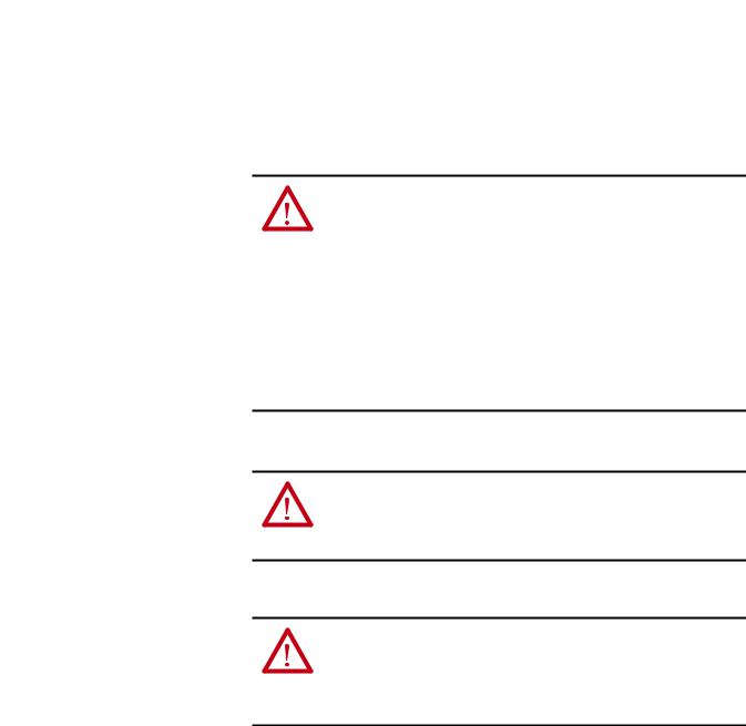
Assemble the System
Attach the module to the controller or an adjacent I/O module before or after mounting. For mounting instructions, see the Panel Mount or DIN Rail Mount sections. To work with a system that is already mounted, see Replace a Module section.
3


 4
4
2 


 1
1


 6 1
6 1 


5
1. Disconnect power.
ATTENTION: Remove power before removing or inserting this module. When you remove or insert a module with power applied, an electrical arc can occur. An electrical arc can cause personal injury or property damage by:
•sending an erroneous signal to your system’s field devices, causing unintended machine motion.
•causing an explosion in a hazardous environment.
Electrical arcing causes excessive wear to contacts on both the module and its mating connector. Worn contacts can create electrical resistance.
2.Check that the bus lever of the module to be installed is in the unlocked (fully right) position.
3.Use the upper and lower tongue-and-groove slots (1) to secure the modules together or to a controller.
4.Move the module back along the tongue-and-groove slots until the bus connectors (2) align with each other.
5.Use your fingers or a small screwdriver to push the bus lever back slightly to clear the positioning tab (3).
6.Move the bus lever fully to the left (4) until it clicks, to enable communication between the controller and module.
7.Verify that it is locked firmly in place.
ATTENTION: When attaching I/O modules, it is important that the bus connectors are securely locked together to be sure of proper electrical connection.
8.Attach an end-cap terminator (5) to the last module in the system by using the tongue-and-groove slots as before.
14 |
Rockwell Automation Publication 1769-UM012B-EN-P - January 2014 |
Compact I/O ASCII Module |
Chapter 1 |
|
|
9. Lock the end-cap bus terminator (6).
IMPORTANT |
You must use a 1769-ECR or 1769-ECL rightor left-end cap to terminate |
|
the end of the serial communication bus. |
|
|
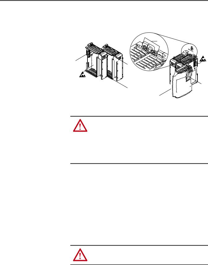
Minimum Space
Maintain spacing, for example, from enclosure walls, wireways, adjacent equipment. Allow 50 mm (2 in) of space on all sides for adequate ventilation.
Side
Controller
|
Top |
|
|
|
|
Compact I/O |
Compact I/O |
Compact I/O |
Compact I/O |
Compact I/O |
End Cap |
Side
Bottom
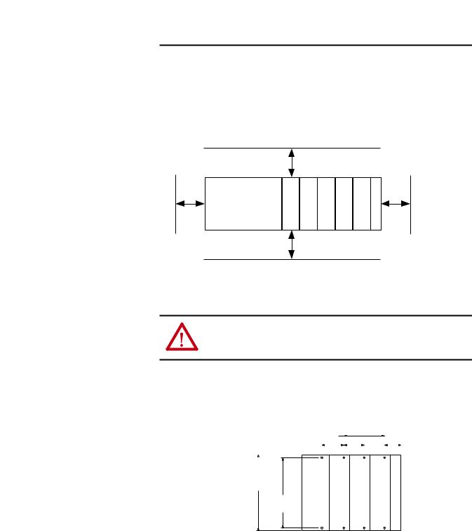
Panel Mount
ATTENTION: During panel or DIN rail mounting of all devices, be sure that all debris (for example, metal chips and wire strands) is kept from falling into the module. Debris that falls into the module could cause damage on powerup.
Mount the module to a panel by using two screws per module. Use M4 or #8 panhead screws. Mounting screws are required on every module.
Panel Mount Procedure with the Dimensional Template
For more than 2 modules:(number of modules - 1) X 35 mm (1.38 in.) |
|
35 |
|
|
|
|
28.5 |
|||||||||
|
|
|
|
|
||||||||||||
Refer to host controller documentationfor this dimension. |
|
|
|
|
|
|
|
|
|
|||||||
|
|
|
|
|
|
|
|
|
(1.38) |
|
|
|
|
(1.12) |
||
|
|
|
|
|
|
|
|
|
|
|
|
|
|
|
|
|
|
|
|
|
|
|
|
|
|
|
|
|
|
|
|
|
|
132
(5.197)
122.6±0.2
(4.826±0.008)
Host Controller |
|
|
Compact I/O |
Compact I/O |
Compact I/O |
Right End Cap |
|||||||||
|
|
|
|
|
|
|
|
|
|
|
|
|
|
|
|
All dimensions
are in mm (inches). Hole spacing tolerance:
±0.4 mm (0.016 in.)
Rockwell Automation Publication 1769-UM012B-EN-P - January 2014 |
15 |

Chapter 1 Compact I/O ASCII Module
Panel Mount Procedure with Modules as a Template
The following procedure lets you use the assembled modules as a template for drilling holes in the panel. Due to module mounting hole tolerance, it is important to follow these procedures.
1.On a clean work surface, assemble no more than three modules.
2.Mark the center of all module-mounting holes on the panel by using the assembled modules as a template.
3.Return the assembled modules to the clean work surface, including any previously mounted modules.
4.Drill and tap the mounting holes for the recommended M4 or #8 screw.
5.Place the modules back on the panel, and check for proper hole alignment.
6.Use the mounting screws to attach the modules to the panel.
If mounting more modules, mount the last one of this group only and put the others aside. This reduces remounting time during drilling and tapping of the next group.
7.Repeat steps 1…6 for any remaining modules.
DIN Rail Mount
IMPORTANT When mounting the CompactLogix system, either use screws to panel mount the system or use DIN rail. Do not use both. Use of both mounting methods can cause hardware damage and cause the system to fail.
The module can be mounted on these DIN rails:
•35 x 7.5 mm (EN 50022 - 35 x 7.5)
•35 x 15 mm (EN 50022 - 35 x 15)
Before mounting the module on a DIN rail, close the DIN rail latches. Press the DIN rail mounting area of the module against the DIN rail. The latches momentarily open and lock into place.
16 |
Rockwell Automation Publication 1769-UM012B-EN-P - January 2014 |
Compact I/O ASCII Module |
Chapter 1 |
|
|
Replace a Module
Ground the Module
The module can be replaced while the system is mounted to a panel or DIN rail.
1. Remove power.
ATTENTION: Remove power before removing or inserting this module. When you remove or insert a module with power applied, an electrical arc can occur. An electrical arc can cause personal injury or property damage by:
•sending an erroneous signal to your system’s field devices, causing unintended machine motion
•causing an explosion in a hazardous environment
Electrical arcing causes excessive wear to contacts on both the module and its mating connector. Worn contacts can create electrical resistance.
2.Remove the upper and lower mounting screws from the module to be removed (or open the DIN latches with a screwdriver).
3.Move the bus lever to the right to disconnect (unlock) the bus.
4.Move the bus lever on the right-side adjacent module to the right (unlock) to disconnect it from the module to be removed.
5.Gently slide the disconnected module forward.
If you feel excessive resistance, verify that the module is disconnected from the bus and mounting screws are removed (or DIN latches opened).
If needed, rock the module slightly from front to back to remove it, or, in a panel-mounted system, to loosen the screws of adjacent modules.
6.Before installing the replacement module, verify that the bus lever on the replacement module and the right-side adjacent module are unlocked (fully right) position.
7.Slide the replacement module into the open slot.
8.Connect the modules together by locking (fully left) the bus levers on the replacement module and the right-side adjacent module.
9.Replace the mounting screws (or snap the module onto the DIN rail).
This product is intended to be mounted to a well-grounded mounting surface such as a metal panel. Additional grounding connections from the module’s mounting tabs or DIN rail (if used) are not required unless the mounting surface cannot be grounded. See Industrial Automation Wiring and Grounding Guidelines, publication 1770-4.1, for additional information.
Rockwell Automation Publication 1769-UM012B-EN-P - January 2014 |
17 |

Chapter 1 Compact I/O ASCII Module
Connect the D-sub Connector
Pins
All the pins are always active.
IMPORTANT Pins unused for a particular physical network must not be connected via the serial cable to any other device. In particular, do not use cables 1747-CP3 and 1756-CP3.
Pin |
RS-232 |
RS-422 |
RS-485 |
|
|
|
|
1 |
Do Not Connect |
Transmit Data - |
Transmit/Receive Data - |
|
|
|
|
2 |
Receive Data |
Do Not Connect |
Do Not Connect |
|
|
|
|
3 |
Transmit Data |
Do Not Connect |
Do Not Connect |
|
|
|
|
4 |
Do Not Connect |
Receive Data - |
Do Not Connect |
|
|
|
|
5 |
Common |
Common |
Common |
|
|
|
|
6 |
Do Not Connect |
Receive Data + |
Do Not Connect |
|
|
|
|
7 |
Request To Send |
Request To Send |
Request To Send |
|
|
|
|
8 |
Clear To Send |
Clear To Send |
Clear To Send |
|
|
|
|
9 |
Do Not Connect |
Transmit Data + |
Transmit/Receive Data + |
|
|
|
|
Figure 1 - RS-232 Wiring Diagram - Module to DTE Device (hardware handshaking disabled)
|
ASCII DTE |
DTE |
9-pin |
25-pin |
|
|
|
||||||
|
|
|
|
|
|
|
|
|
|
|
|
|
|
|
|
1 |
NC |
|
|
|
|
DCD |
1 |
8 |
|
|
|
|
|
|
|
|
|
|
|
|
|||||
|
|
|
|
|
|
|
|
|
|
|
|
|
|
|
|
2 |
RXD |
|
|
|
|
TXD |
3 |
2 |
|
|
|
|
|
|
|
|
|
|
|
|
|||||
|
|
|
|
|
|
|
|
|
|
|
|
|
|
|
|
3 |
TXD |
|
|
|
|
RSD |
2 |
3 |
|
|
|
|
|
|
|
|
|
|
|
|
|||||
|
|
|
|
|
|
|
|
|
|
|
|
|
|
|
|
4 |
NC |
|
|
|
|
DSR |
6 |
6 |
|
|
|
|
|
|
|
|
|
|
|
|
|||||
|
|
|
|
|
|
|
|
|
|
|
|
|
|
|
|
5 |
COM |
|
|
|
|
COM |
5 |
7 |
|
|
|
|
|
|
|
|
|
|
|
|
|||||
|
|
|
|
|
|
|
|
|
|
|
|
|
|
|
|
6 |
NC |
|
|
|
|
DTR |
4 |
20 |
|
|
|
|
|
|
|
|
|
|
|
|
|||||
|
|
|
|
|
|
|
|
|
|
|
|
|
|
|
|
7 |
RTS |
|
|
|
|
CTS |
8 |
5 |
|
|
|
|
|
|
|
|
|
|
|
|
|||||
|
|
|
|
|
|
|
|
|
|
|
|
|
|
|
|
8 |
CTS |
|
|
|
|
RTS |
7 |
4 |
|
|
|
|
|
|
|
|
|
|
|
|
|||||
|
|
|
|
|
|
|
|
|
|
|
|
|
|
|
|
9 |
NC |
|
|
|
|
GND(1) |
|
1 |
|
|
|
(1) Connect to the shield of the cable.
18 |
Rockwell Automation Publication 1769-UM012B-EN-P - January 2014 |
Compact I/O ASCII Module |
Chapter 1 |
|
|
Figure 2 - RS-232 Wiring Diagram - Module to Printer (hardware handshaking enabled, standard printer adapter cable)
ASCII DTE |
DTE |
9-pin |
25-pin |
||||||
|
|
|
|
|
|
|
|
|
|
1 |
NC |
|
|
|
|
|
CD |
1 |
8 |
|
|
|
|
|
|||||
|
|
|
|
|
|
|
|
|
|
2 |
RXD |
|
|
|
|
|
TXD |
3 |
2 |
|
|
|
|
|
|||||
|
|
|
|
|
|
|
|
|
|
3 |
TXD |
|
|
|
|
|
RXD |
2 |
3 |
|
|
|
|
|
|||||
|
|
|
|
|
|
|
|
|
|
4 |
NC |
|
|
|
|
|
DSR |
6 |
6 |
|
|
|
|
|
|
|
|
|
|
5 |
COM |
|
|
|
|
|
COM |
5 |
7 |
|
|
|
|
|
|||||
|
|
|
|
|
|
|
|
|
|
6 |
NC |
|
|
|
|
|
DTR |
4 |
20 |
|
|
|
|
|
|
|
|
|
|
7 |
RTS |
|
|
|
|
|
CTS |
8 |
5 |
|
|
|
|
|
|||||
|
|
|
|
|
|
|
|
|
|
8 |
CTS |
|
|
|
|
|
RTS |
7 |
4 |
|
|
|
|
|
|||||
|
|
|
|
|
|
|
|
|
|
9 |
N.C. |
|
|
|
|
|
RI |
9 |
22 |
|
|
|
|
|
|
|
|
|
|
|
|
|
|
|
|
|
GND |
|
1 |
|
|
|
|
|
|
|
|
|
|
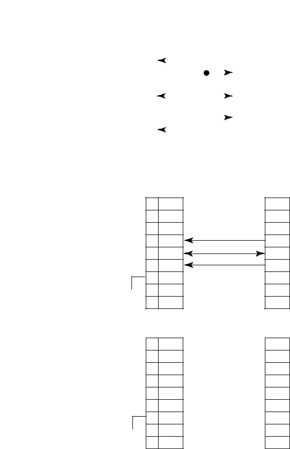
Figure 3 - RS-422 Wiring Diagram
ASCII
1 TXD-  RXD-
RXD-
2NC
3NC
4 |
RXD- |
TXD- |
5 |
COM |
COM |
6 |
RXD+ |
TXD+ |
7RTS
 8 CTS
8 CTS
9 TXD+  RXD+
RXD+
Figure 4 - RS-485 Wiring Diagram
ASCII
1 TRXD- 
 TRXD-
TRXD-
2NC
3NC
4NC
5 COM 
 COM
COM
6 NC
7RTS
 8 CTS
8 CTS
9 TRXD+ 
 TRXD+
TRXD+
Rockwell Automation Publication 1769-UM012B-EN-P - January 2014 |
19 |

Chapter 1 Compact I/O ASCII Module
Notes:
20 |
Rockwell Automation Publication 1769-UM012B-EN-P - January 2014 |
Chapter 2
Configure the 1769-ASCII
Module
Configure the 1769-ASCII Module
This chapter describes how to configure and program the 1769-ASCII module with CompactLogix controllers and the MicroLogix 1500 controller.
Starting on page 34, there are three example Logix Designer programs using the 1769-ASCII module’s Add-On Profile. The examples use the Add-On Profile instead of the generic module profile. Using the Add-On Profile saves you time by making the configuration of the module easier, for example, not having to input a lot of data.
•Connect to Channel 0 of the Module in Alternating Mode on page 34
•Connect to Both Channels of the Module in Alternating Mode on page 41
•Connect to Both Channels of the 1769-ASCII Module in Simultaneous Mode on page 49
To access these Logix Designer programs, see the Knowledgebase Technote # 64203 at https://rockwellautomation.custhelp.com/app/answers/detail/a_id/ 64203.
Follow these steps to add and configure the 1769-ASCII module.
1.Right click on the 1769 Compact Bus in your Logix Designer project and choose New Module.
Rockwell Automation Publication 1769-UM012B-EN-P - January 2014 |
21 |
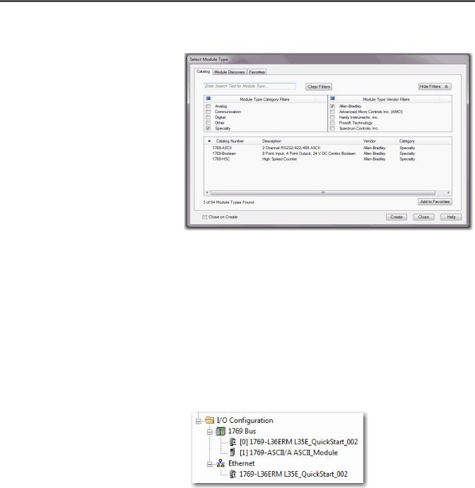
Chapter 2 Configure the 1769-ASCII Module
2.In the Enter test search or module type field, type 1769-ASCII or clear the checkboxes and check Specialty.
3.Select the 1769-ASCII module and click Create.
4.Close the Select Module Type dialog box.
TIP |
If you are using RSLogix5000 software, version 16 and later and do not see the |
|
1769-ASCII module as an option, you must download the module’s Add-On |
|
Profile. |
|
The Add-On Profile can be downloaded and installed from https:// |
|
download.rockwellautomation.com/esd/ |
|
download.aspx?downloadid=addonprofiles |
|
RSLogix5000 software, version 16 is the minimum revision compatible with |
|
the 1769-ASCII module Add-On-Profile. |
The module appears in the configuration tree.
5. Right-click on the module and choose Properties.
22 |
Rockwell Automation Publication 1769-UM012B-EN-P - January 2014 |

Configure the 1769-ASCII Module |
Chapter 2 |
|
|
The Module Properties Dialog box appears.
6.Review and make sure you have the correct module.
7.Type a name.
8.Type a description, if needed.
9.Assign a slot number to the module.
10.Review the Module Definition area and make sure the information is correct.
11.Click Change on the General tab to modify the module definition parameters.
The Module Definition box appears.
TIP |
The examples used later in this chapter, has electronic keying disabled but |
|
compatible keying is suggested. For mor information, see Electronic Keying on |
|
page 105. |
Rockwell Automation Publication 1769-UM012B-EN-P - January 2014 |
23 |

Chapter 2 Configure the 1769-ASCII Module
Module Definition Dialog Box
The Module Definition dialog box contains a set of configuration parameters that affects data transmission between the controller and the I/O module.
TIP |
Online edits are not possible when the controller is in RUN mode. Online edits |
|
must be made only when the controller is in Remote Run or Program modes. |
The Change button on the Module Properties General tab provides access where the listed parameters can be changed.
This is where you specify the Series, Revision, and Electronic Keying. You can do the following:
•Choose connection type
•Select alternating or simultaneous mode
•Assign the data format type
Table 1 - Module Definition Parameters Descriptions
Parameter |
Description |
|
|
Series |
Module’s hardware series. |
|
|
Revision |
Major and minor firmware revision levels used on the module. |
|
|
Electronic Keying |
When you configure a module, you specify the slot number for the module. However, it is |
|
possible to purposely or accidentally place a different module in that slot. Electronic keying lets |
|
you protect your system against the accidental placement of the wrong module in a slot. The |
|
chosen keying option determines how closely any module in a slot must match the |
|
configuration for that slot before the controller opens a connection to the module. There are |
|
different keying options depending on your application needs. See Using Electronic Keying on |
|
page 105 for detailed information. |
|
|
Connection |
The connection type between the controller writing the configuration and the I/O module is |
|
Output. |
|
|
Data Format |
Integer data transferred between the controller and I/O module and what tags are generated |
|
when the configuration is complete. |
|
|
24 |
Rockwell Automation Publication 1769-UM012B-EN-P - January 2014 |

Configure the 1769-ASCII Module |
Chapter 2 |
|
|
1.In the Module Definition dialog box click the Channel tab.
2.Configure channel parameters and click OK.
Each channel can be configured for 4…200 characters. For Simultaneous Mode, the sum of Channel 1 and Channel 2 for Receive and Transmit characters cannot exceed 200 bytes.
The module's RPI can be configured through Connection tab. RPI can be configured in multiples of 0.5. The RPI can be configured for 1.0 - 750.0 in multiples of 0.5ms. Values entered are rounded down to nearest multiple of 0.5ms. for example 2.1ms is rounded down to 2.0ms.
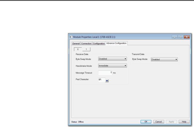
ASCII protocol configuration can be done under Configuration tab. Channels 0 and 1 can have different configuration. Advanced ASCII protocol configuration like Byte Swap Mode can be done under Advanced Configuration tab. Channels 0 and 1 can have different advanced configurations.
Rockwell Automation Publication 1769-UM012B-EN-P - January 2014 |
25 |
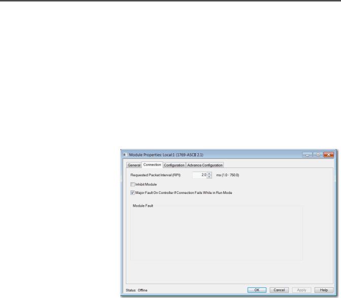
Chapter 2 Configure the 1769-ASCII Module
1769-ASCII Module Connections Dialog Box
This tab displays information about the condition of the connection between the module and the controller.
TIP |
Online edits are not possible when the controller is in RUN mode. Online edits |
|
must be made only when the controller is in Remote Run or Program modes. |
Use this tab to define controller to module behavior.
•Select a requested packet interval (RPI)
•Choose to inhibit or uninhibit the module
•Configure the controller so that a loss of connection to this module causes a major fault
•View module faults
26 |
Rockwell Automation Publication 1769-UM012B-EN-P - January 2014 |

Configure the 1769-ASCII Module Chapter 2
Table 2 - Connection Tab Descriptions
Parameter |
Descriptions |
|
|
RPI |
Enter the requested rate of packet arrival (connection update rate). The RPI specifies the interval at which data is transmitted or received |
|
over a connection. When scanned on the local bus or over an EtherNet/IP network, I/O modules are scanned at the RPI specified in the |
|
module configuration. |
|
Typically, you configure an RPI in milliseconds (ms). The connection is scheduled to move data to or from the module at least this often or |
|
the connection fails with the Connection Not Scheduled fault. The minimum and maximum RPI values are shown parenthetically to the |
|
right of the box/spin control. |
|
|
Major Fault on Controller If Connection |
This option determines how the controller is affected if the connection to an I/O module fails in Run mode or if the controller is unable to |
Fails While in Run Mode |
establish a connection to the module. You can configure the project so that a connection failure causes a major fault on the controller or |
|
not. The default setting is for the option to be disabled. |
|
For example, if this option is enabled and an I/O module is removed while in Run mode, a major fault occurs on the controller. The default |
|
setting for the embedded I/O module is that this option is enabled. The default setting for local expansion modules is that this option is |
|
disabled. |
|
|
Inhibit Module |
Check or Uncheck this box to inhibit/uninhibit your connection to the module. Inhibiting the module causes the connection to the |
|
module to be broken and may result in lost data. If the module is inhibited, the module in the controller organizer displays the attention |
|
icon. |
|
If you inhibit the module while you are online and connected to the module, the connection to the module is nicely closed. The module's |
|
outputs will go to the last configured Program mode state. |
|
• If you inhibit the module while online but a connection to the module has not been established (due to an error condition or fault), |
|
the module is inhibited. The module status information changes to indicate that the module is 'Inhibited' and not 'Faulted'. |
|
• If you uninhibit a module (clear the checkbox) while online, and no fault condition occurs, a connection is made to the module and the |
|
module is dynamically reconfigured (if you are the owner controller) with the configuration you have created for that module. If you |
|
are a listener (have chosen a ‘Listen Only’ Communications Format), you cannot re-configure the module. |
|
• If you uninhibit a module while online and a fault condition occurs, a connection is not made to the module. |
|
|
Module Fault |
View module faults. |
|
These are some common message that you may see in the Module Fault area. |
|
Connection Request Error |
|
The controller is attempting to make a connection to the module and has received an error. The connection was not made. |
|
Service Request Error |
|
The controller is attempting to request a service from the module and has received an error. The service was not performed successfully. |
|
Module Configuration Invalid |
|
The configuration in the module is invalid. (This error is commonly caused by the Electronic Key Passed fault.) |
|
Electronic Keying Mismatch |
|
Electronic Keying is enabled and some part of the keying information differs between the software and the module. |
|
|
Rockwell Automation Publication 1769-UM012B-EN-P - January 2014 |
27 |
Chapter 2 Configure the 1769-ASCII Module
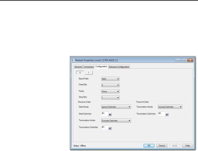
1769-ASCII Module Configuration Dialog Box
Use this dialog box to configure the ASCII parameters.
TIP |
Online edits to a module's configuration do not take effect until the module |
|
connection is reestablished. This can be done by inhibiting/uninhibited the |
|
module using the checkbox on Connection tab. The module operation is |
|
interrupted while connection is inhibited. |
Table 3 - Module Properties Dialog Box - Configuration Tab Parameter Descriptions
Parameter |
Description |
|
|
Channel |
Choose the channel (0 or 1) for which parameters are configured. |
|
|
Baud Rate |
Enter the baud rate for the channel. Valid values are as follows. |
|
1200 |
|
2400 |
|
4800 |
|
9600 (default) |
|
19,200 |
|
38,400 |
|
57,600 |
|
115,200 |
|
Baud Rate appears dimmed when controller is in Run mode. Online edits can only be done when the mode or key switch is in the Remote or |
|
Program position. |
|
|
Serial Data Formats |
Use Data Bits, Parity, and Stop Bits to configure serial data formats. |
|
|
Data Bits |
Choose 7 (default) or 8 for the Data Bits. Data Bits appears dimmed Run mode. |
|
|
Parity |
Choose Odd, Even, or None (default) for the Parity. Parity appears dimmed Run mode. |
|
|
28 |
Rockwell Automation Publication 1769-UM012B-EN-P - January 2014 |

Configure the 1769-ASCII Module Chapter 2
Table 3 - Module Properties Dialog Box - Configuration Tab Parameter Descriptions (Continued)
Parameter |
Description |
|
|
|
|
|
|||
Stop Bits |
Choose 1 or 2 (default) for the Stop Bits. Stop Bits appear dimmed Run mode. These are the Valid Data Bits, Parity, and Stop Bits combinations |
|||
|
Data Bits |
Parity |
Stop Bits |
|
|
7 |
|
None |
2 |
|
7 |
|
Even |
1 |
|
7 |
|
Odd |
1 |
|
7 |
|
Even |
2 |
|
7 |
|
Odd |
2 |
|
8 |
|
None |
1 |
|
8 |
|
None |
2 |
|
8 |
|
Even |
1 |
|
8 |
|
Odd |
1 |
|
|
|
|
|
Receive Data |
Start Mode |
|
|
|
|
• |
Ignore Delimiter (default) |
||
|
• |
Exclude Delimiter |
|
|
|
• |
Include Delimiter |
|
|
|
Start Mode appears dimmed Run mode. |
|||
|
Start Delimiter |
|
||
|
Valid values are any ASCII character (7 bit – 0…127; 8 bit – 0…255). These are the supported special characters. |
|||
|
Character |
Description |
||
|
$$ |
|
Dollar Sign ($24) |
|
|
$’ |
|
Single Quote ($27) |
|
|
$L |
|
Line Feed ($0A) |
|
|
$P |
|
Form Feed ($0C) |
|
|
$R |
|
Carriage Return ($0D) |
|
|
$T |
|
Tab ($09) |
|
|
Start Delimiter appears dimmed. |
|||
|
|
|||
Termination Mode |
Configure the channel’s termination mode. These are the valid values. |
|||
|
• |
Ignore Delimiter |
|
|
|
• |
Exclude Delimiter |
|
|
|
• |
Include Delimiter (default) |
||
|
Termination Mode appears dimmed in Run mode. |
|||
|
|
|||
Termination Delimiter |
Configure the channel’s termination delimiter. Valid values are any ASCII character (7 bit – 0…127; 8 bit – 0…255). The following special |
|||
|
characters are supported. |
|
||
|
Character |
Description |
||
|
$$ |
|
Dollar Sign ($24) |
|
|
$’ |
|
Single Quote ($27) |
|
|
$L |
|
Line Feed ($0A) |
|
|
$P |
|
Form Feed ($0C) |
|
|
$R |
|
Carriage Return ($0D) |
|
|
$T |
|
Tab ($09) |
|
|
Termination Delimiter appears dimmed in Run mode. |
|||
|
|
|||
Transmit Data |
Configure the channel’s termination mode. These are the valid values. |
|||
|
• |
Ignore Delimiter |
|
|
|
• |
Exclude Delimiter |
|
|
|
• |
Include Delimiter (default) |
||
|
Termination Mode appears dimmed in Run mode. |
|||
|
|
|
|
|
Rockwell Automation Publication 1769-UM012B-EN-P - January 2014 |
29 |
Chapter 2 Configure the 1769-ASCII Module
1769-ASCII Module Advanced Configuration Dialog Box
Use this dialog box to configure advanced parameters, such as receiving and transmitting data.
30 |
Rockwell Automation Publication 1769-UM012B-EN-P - January 2014 |
Loading...