


 Loading...
Allen-Bradley |
|
ControlNet™ |
|
Communications |
User Manual |
Module |
|
Cat. No. 1203-CN1 |
|
Firmware 2.xxx |
|

Important User Information |
Because of the variety of uses for the products described in this publi- |
||
|
cation, those responsible for the application and use of this control |
||
|
equipment must satisfy themselves that all necessary steps have been |
||
|
taken to assure that each application and use meets all performance |
||
|
and safety requirements, including any applicable laws, regulations, |
||
|
codes and standards. |
||
|
The illustrations, charts, sample programs and layout examples |
||
|
shown in this guide are intended solely for purposes of example. |
||
|
Since there are many variables and requirements associated with any |
||
|
particular installation, Rockwell Automation does not assume |
||
|
responsibility or liability (to include intellectual property liability) for |
||
|
actual use based upon the examples shown in this publication. |
||
|
Rockwell Automation publication SGI-1.1, Safety Guidelines for the |
||
|
Application, Installation, and Maintenance of Solid-State Control |
||
|
(available from your local Rockwell Automation office), describes |
||
|
some important differences between solid-state equipment and |
||
|
electromechanical devices that should be taken into consideration |
||
|
when applying products such as those described in this publication. |
||
|
Reproduction of the contents of this copyrighted publication, in |
||
|
whole or in part, without written permission of Rockwell |
||
|
Automation, is prohibited. |
||
|
Throughout this manual we use notes to make you aware of safety |
||
|
considerations: |
||
|
|
|
|
|
! |
ATTENTION: Identifies information about practices |
|
|
or circumstances that can lead to personal injury or |
||
|
death, property damage or economic loss. |
||
|
|
|
|
Attention statements help you to:
•Identify a hazard.
•Avoid the hazard.
•Recognize the consequences.
Important: Identifies information that is critical for successful application and understanding of the product.
|
|
Summary of Changes |
|
|
Summary of Changes |
|
|
Updated Information |
The following changes to this manual have occurred since Publication |
||
|
1203-5.13 – July 1998, P/N189939 (02). |
||
Getting Started |
Section: Establishing a Serial Connection with the 1203-CN1 Module |
||
|
Paragraph added: |
||
|
DriveExplorer (v1.01 or higher) software can now also be used on |
||
|
1203-CN1s that are v2.001 or higher. Do not use DriveExplorer |
||
|
software with v1.xxx CN1s. |
||
Appendix A |
Power Consumption specification updated to 250mA at 24V DC |
||
|
(-20% / +30%). |
|
|
Appendix B |
|
|
|
Parameter 21 Serial Port Rate |
Valid Value/Settings updated. |
||
|
0 |
= 2400 |
|
|
1 |
= 4800 |
|
|
2 |
= 9600 |
|
|
3 |
= 19.2K |
|
|
4 |
= 38.4K |
|
|
Default setting updated. |
||
|
2 |
= 9600 |
|
|
Important statement added to description. |
||
|
Important: These settings are valid for v1.004 or higher CN1s. |
||
|
v1.003 or lower CN1s only have two settings: 0 = 9600 and |
||
|
1 |
= 19.2K. |
|
Appendix D |
Section: Class Code 0x99 - SCANport Pass-Through Link Object |
||
|
Common Services: |
||
Service Code updated. 0x0E
0x10
Publication 1203-5.13 – February, 2002

Summary of Changes
Notes:
Publication 1203-5.13 – February, 2002

Table of Contents
Preface |
Objectives . . . . . . . . . . . . . . . . . . . . . . . . . . . . . . . . . . . . . . . . . . . . . . . . . . . . . . . . . . |
P-1 |
|
Who Should Use This Manual?. . . . . . . . . . . . . . . . . . . . . . . . . . . . . . . . . . . . . . . . . . |
P-1 |
|
What Is the 1203-CN1 ControlNet Communications Module? . . . . . . . . . . . . . . . . . . |
P-1 |
|
Purpose of this Manual . . . . . . . . . . . . . . . . . . . . . . . . . . . . . . . . . . . . . . . . . . . . . . . . |
P-1 |
|
Contents of this Manual . . . . . . . . . . . . . . . . . . . . . . . . . . . . . . . . . . . . . . . . . . . . . |
P-2 |
|
Safety Precautions . . . . . . . . . . . . . . . . . . . . . . . . . . . . . . . . . . . . . . . . . . . . . . . . . . . |
P-3 |
|
Terms and Abbreviations . . . . . . . . . . . . . . . . . . . . . . . . . . . . . . . . . . . . . . . . . . . . . . |
P-3 |
|
Conventions Used in this Manual . . . . . . . . . . . . . . . . . . . . . . . . . . . . . . . . . . . . . . . . |
P-4 |
|
Rockwell Automation Support. . . . . . . . . . . . . . . . . . . . . . . . . . . . . . . . . . . . . . . . . . . |
P-4 |
|
Local Product Support . . . . . . . . . . . . . . . . . . . . . . . . . . . . . . . . . . . . . . . . . . . . . . |
P-4 |
|
Technical Product Assistance . . . . . . . . . . . . . . . . . . . . . . . . . . . . . . . . . . . . . . . . . |
P-4 |
Overview |
Chapter 1 |
|
|
Chapter Objectives . . . . . . . . . . . . . . . . . . . . . . . . . . . . . . . . . . . . . . . . . . . . . . . . . . . |
1-1 |
|
Overview of the 1203-CN1 ControlNet Communications Module. . . . . . . . . . . . . . . . |
1-1 |
|
What Is ControlNet? . . . . . . . . . . . . . . . . . . . . . . . . . . . . . . . . . . . . . . . . . . . . . . . . . . |
1-2 |
|
SCANport Products. . . . . . . . . . . . . . . . . . . . . . . . . . . . . . . . . . . . . . . . . . . . . . . . . . . |
1-3 |
|
What Hardware Is Included?. . . . . . . . . . . . . . . . . . . . . . . . . . . . . . . . . . . . . . . . . . . . |
1-4 |
|
Overview of Setting Up the 1203-CN1 Module . . . . . . . . . . . . . . . . . . . . . . . . . . . . . . |
1-5 |
|
Required Tools and Equipment. . . . . . . . . . . . . . . . . . . . . . . . . . . . . . . . . . . . . . . . . . |
1-5 |
Installation |
Chapter 2 |
|
|
Chapter Objectives . . . . . . . . . . . . . . . . . . . . . . . . . . . . . . . . . . . . . . . . . . . . . . . . . . . |
2-1 |
|
Required Tools and Equipment. . . . . . . . . . . . . . . . . . . . . . . . . . . . . . . . . . . . . . . . . . |
2-1 |
|
Selecting Cables . . . . . . . . . . . . . . . . . . . . . . . . . . . . . . . . . . . . . . . . . . . . . . . . . . . . . |
2-1 |
|
SCANport Cables . . . . . . . . . . . . . . . . . . . . . . . . . . . . . . . . . . . . . . . . . . . . . . . . . . |
2-2 |
|
ControlNet Cable Taps . . . . . . . . . . . . . . . . . . . . . . . . . . . . . . . . . . . . . . . . . . . . . . |
2-2 |
|
Electrostatic Discharge Precautions . . . . . . . . . . . . . . . . . . . . . . . . . . . . . . . . . . . . . . |
2-3 |
|
Installing Your 1203-CN1 Module . . . . . . . . . . . . . . . . . . . . . . . . . . . . . . . . . . . . . . . . |
2-4 |
|
Removing the 1203-CN1 Module . . . . . . . . . . . . . . . . . . . . . . . . . . . . . . . . . . . . . . . . |
2-8 |
Publication 1203-5.13 – February, 2002

ii Table of Contents
Getting Started |
Chapter 3 |
|
|
Chapter Objectives . . . . . . . . . . . . . . . . . . . . . . . . . . . . . . . . . . . . . . . . . . . . . . . . . |
. 3-1 |
|
Factory-Default Settings for the 1203-CN1 Module’s Parameters. . . . . . . . . . . . . . |
. 3-1 |
|
Required Tools and Equipment . . . . . . . . . . . . . . . . . . . . . . . . . . . . . . . . . . . . . . . . . |
3-2 |
|
Electrostatic Discharge Precautions . . . . . . . . . . . . . . . . . . . . . . . . . . . . . . . . . . . . . |
3-2 |
|
Establishing a Serial Connection with the 1203-CN1 Module . . . . . . . . . . . . . . . . . . |
3-2 |
|
Using a PC Running Terminal Emulation Software . . . . . . . . . . . . . . . . . . . . . . . . |
3-3 |
|
Using a VT100-Compatible Terminal . . . . . . . . . . . . . . . . . . . . . . . . . . . . . . . . . . . |
3-7 |
|
Navigation Techniques . . . . . . . . . . . . . . . . . . . . . . . . . . . . . . . . . . . . . . . . . . . . . . . |
3-8 |
|
Editing Parameters in the 1203-CN1 Module . . . . . . . . . . . . . . . . . . . . . . . . . . . . . . |
3-9 |
|
Displaying and Clearing the Event Queue in the 1203-CN1 Module. . . . . . . . . . . . |
3-10 |
|
Displaying the 1203-CN1 module’s Current I/O Data . . . . . . . . . . . . . . . . . . . . . . . |
3-11 |
|
Displaying the DF1 Protocol Statistics in the 1203-CN1 Module. . . . . . . . . . . . . . . |
3-12 |
|
Viewing Your 1203-CN1 Module’s Serial Number. . . . . . . . . . . . . . . . . . . . . . . . . . |
3-13 |
|
Performing a Flash Upgrade to the 1203-CN1 Module . . . . . . . . . . . . . . . . . . . . . . |
3-14 |
Configuring a |
Chapter 4 |
|
Controller to |
Chapter Objectives . . . . . . . . . . . . . . . . . . . . . . . . . . . . . . . . . . . . . . . . . . . . . . . . . . |
4-1 |
Communicate with the |
What is RSNetWorx?. . . . . . . . . . . . . . . . . . . . . . . . . . . . . . . . . . . . . . . . . . . . . . . . . |
4-1 |
1203-CN1 Module |
Required Equipment and Software . . . . . . . . . . . . . . . . . . . . . . . . . . . . . . . . . . . . . . |
4-1 |
|
Configuring a Controller to Communicate with the 1203-CN1 Module . . . . . . . . . . . |
4-2 |
|
Using Online Mode in RSNetWorx . . . . . . . . . . . . . . . . . . . . . . . . . . . . . . . . . . . . |
4-2 |
|
Mapping the 1203-CN1 Module to the ControlNet Network . . . . . . . . . . . . . . . . . |
4-6 |
|
Verifying Network Properties . . . . . . . . . . . . . . . . . . . . . . . . . . . . . . . . . . . . . . . . . |
4-1 |
PLC Ladder Logic |
Chapter 5 |
|
Programming |
Chapter Objectives . . . . . . . . . . . . . . . . . . . . . . . . . . . . . . . . . . . . . . . . . . . . . . . . . . |
5-1 |
|
What Is RSLogix5? . . . . . . . . . . . . . . . . . . . . . . . . . . . . . . . . . . . . . . . . . . . . . . . . . . |
5-1 |
|
What Are PLC Ladder Logic Programs? . . . . . . . . . . . . . . . . . . . . . . . . . . . . . . . . . . |
5-2 |
|
Required Equipment and Software . . . . . . . . . . . . . . . . . . . . . . . . . . . . . . . . . . . . . . |
5-3 |
|
Example Ladder Logic Program . . . . . . . . . . . . . . . . . . . . . . . . . . . . . . . . . . . . . . . . |
5-3 |
Using Messages |
Chapter 6 |
|
|
Chapter Objectives . . . . . . . . . . . . . . . . . . . . . . . . . . . . . . . . . . . . . . . . . . . . . . . . . . |
6-1 |
|
Required Equipment and Software . . . . . . . . . . . . . . . . . . . . . . . . . . . . . . . . . . . . . . |
6-1 |
|
Using Messages . . . . . . . . . . . . . . . . . . . . . . . . . . . . . . . . . . . . . . . . . . . . . . . . . . . . |
6-1 |
|
Examples. . . . . . . . . . . . . . . . . . . . . . . . . . . . . . . . . . . . . . . . . . . . . . . . . . . . . . . . . . |
6-2 |
|
Example PLC-5 Typed Read of 10 Parameter Values . . . . . . . . . . . . . . . . . . . . . . |
6-2 |
|
Example PLC-5 Typed Read of All Information about a Parameter. . . . . . . . . . . . |
6-4 |
|
Example Fault Queue Read Emulated Block Transfer . . . . . . . . . . . . . . . . . . . . . . |
6-6 |
|
More Information on Emulated Block Transfers . . . . . . . . . . . . . . . . . . . . . . . . . . . |
6-8 |
Publication 1203-5.13 – February, 2002

Table of Contents iii
Troubleshooting |
Chapter 7 |
|
|
Chapter Objectives . . . . . . . . . . . . . . . . . . . . . . . . . . . . . . . . . . . . . . . . . . . . . . . . . . |
7-1 |
|
LEDs on the 1203-CN1 Module. . . . . . . . . . . . . . . . . . . . . . . . . . . . . . . . . . . . . . . . . |
7-1 |
|
Understanding the ControlNet LEDs . . . . . . . . . . . . . . . . . . . . . . . . . . . . . . . . . . . . . |
7-2 |
|
Understanding the SCANport LED . . . . . . . . . . . . . . . . . . . . . . . . . . . . . . . . . . . . . . |
7-3 |
|
Understanding the Module LED . . . . . . . . . . . . . . . . . . . . . . . . . . . . . . . . . . . . . . . . |
7-4 |
Specifications |
Appendix A |
|
|
Appendix Objectives . . . . . . . . . . . . . . . . . . . . . . . . . . . . . . . . . . . . . . . . . . . . . . . . |
. A-1 |
|
Specifications . . . . . . . . . . . . . . . . . . . . . . . . . . . . . . . . . . . . . . . . . . . . . . . . . . . . . |
. A-1 |
1203-CN1 Module |
Appendix B |
|
Parameters |
Appendix Objectives . . . . . . . . . . . . . . . . . . . . . . . . . . . . . . . . . . . . . . . . . . . . . . . . . |
B-1 |
|
What Are Datalinks? . . . . . . . . . . . . . . . . . . . . . . . . . . . . . . . . . . . . . . . . . . . . . . . . . |
B-1 |
|
What Are Fault Configurable Inputs? . . . . . . . . . . . . . . . . . . . . . . . . . . . . . . . . . . . . |
B-1 |
|
Parameters . . . . . . . . . . . . . . . . . . . . . . . . . . . . . . . . . . . . . . . . . . . . . . . . . . . . . . . . |
B-2 |
N-File Structure |
Appendix C |
|
|
Appendix Objectives . . . . . . . . . . . . . . . . . . . . . . . . . . . . . . . . . . . . . . . . . . . . . . . . . |
C-1 |
|
N-File Structure . . . . . . . . . . . . . . . . . . . . . . . . . . . . . . . . . . . . . . . . . . . . . . . . . . . . . |
C-1 |
ControlNet Objects |
Appendix D |
|
|
Appendix Objectives . . . . . . . . . . . . . . . . . . . . . . . . . . . . . . . . . . . . . . . . . . . . . . . . . |
D-1 |
|
Object Classes . . . . . . . . . . . . . . . . . . . . . . . . . . . . . . . . . . . . . . . . . . . . . . . . . . . . . |
D-1 |
|
Class Code 0x01 — Identity Object. . . . . . . . . . . . . . . . . . . . . . . . . . . . . . . . . . . . . . |
D-2 |
|
Class Attributes . . . . . . . . . . . . . . . . . . . . . . . . . . . . . . . . . . . . . . . . . . . . . . . . . . . |
D-2 |
|
Instances . . . . . . . . . . . . . . . . . . . . . . . . . . . . . . . . . . . . . . . . . . . . . . . . . . . . . . . . |
D-2 |
|
Instance Attributes. . . . . . . . . . . . . . . . . . . . . . . . . . . . . . . . . . . . . . . . . . . . . . . . . |
D-3 |
|
Common Services . . . . . . . . . . . . . . . . . . . . . . . . . . . . . . . . . . . . . . . . . . . . . . . . . |
D-3 |
|
Get_Attribute_All Response . . . . . . . . . . . . . . . . . . . . . . . . . . . . . . . . . . . . . . . . . |
D-4 |
|
Class Code 0x02 — Message Router Object . . . . . . . . . . . . . . . . . . . . . . . . . . . . . . |
D-5 |
|
Class Attributes . . . . . . . . . . . . . . . . . . . . . . . . . . . . . . . . . . . . . . . . . . . . . . . . . . . |
D-5 |
|
Instances . . . . . . . . . . . . . . . . . . . . . . . . . . . . . . . . . . . . . . . . . . . . . . . . . . . . . . . . |
D-5 |
|
Instance Attributes. . . . . . . . . . . . . . . . . . . . . . . . . . . . . . . . . . . . . . . . . . . . . . . . . |
D-6 |
|
Common Services . . . . . . . . . . . . . . . . . . . . . . . . . . . . . . . . . . . . . . . . . . . . . . . . . |
D-6 |
|
Get_Attribute_All Response . . . . . . . . . . . . . . . . . . . . . . . . . . . . . . . . . . . . . . . . . |
D-6 |
|
Class Code 0x04 — Assembly Object. . . . . . . . . . . . . . . . . . . . . . . . . . . . . . . . . . . . |
D-7 |
|
Class Attributes . . . . . . . . . . . . . . . . . . . . . . . . . . . . . . . . . . . . . . . . . . . . . . . . . . . |
D-7 |
|
Instances . . . . . . . . . . . . . . . . . . . . . . . . . . . . . . . . . . . . . . . . . . . . . . . . . . . . . . . . |
D-7 |
|
Instance Attributes. . . . . . . . . . . . . . . . . . . . . . . . . . . . . . . . . . . . . . . . . . . . . . . . . |
D-7 |
|
Common Services . . . . . . . . . . . . . . . . . . . . . . . . . . . . . . . . . . . . . . . . . . . . . . . . . |
D-8 |
|
Class Code 0x06 — Connection Manager Object. . . . . . . . . . . . . . . . . . . . . . . . . . . |
D-9 |
|
Class Attributes . . . . . . . . . . . . . . . . . . . . . . . . . . . . . . . . . . . . . . . . . . . . . . . . . . . |
D-9 |
|
Instances . . . . . . . . . . . . . . . . . . . . . . . . . . . . . . . . . . . . . . . . . . . . . . . . . . . . . . . . |
D-9 |
|
Instance Attributes. . . . . . . . . . . . . . . . . . . . . . . . . . . . . . . . . . . . . . . . . . . . . . . . . |
D-9 |
|
Common Services . . . . . . . . . . . . . . . . . . . . . . . . . . . . . . . . . . . . . . . . . . . . . . . . |
D-10 |
Publication 1203-5.13 – February, 2002
iv |
Table of Contents |
Class Code 0x07 — Register Object. . . . . . . . . . . . . . . . . . . . . . . . . . . . . . . . . . . . D-11
Class Attributes . . . . . . . . . . . . . . . . . . . . . . . . . . . . . . . . . . . . . . . . . . . . . . . . . . D-11 Instances . . . . . . . . . . . . . . . . . . . . . . . . . . . . . . . . . . . . . . . . . . . . . . . . . . . . . . . D-11 Instance Attributes. . . . . . . . . . . . . . . . . . . . . . . . . . . . . . . . . . . . . . . . . . . . . . . . D-12 Common Services . . . . . . . . . . . . . . . . . . . . . . . . . . . . . . . . . . . . . . . . . . . . . . . . D-12 Class Code 0x0F — Parameter Object . . . . . . . . . . . . . . . . . . . . . . . . . . . . . . . . . . D-13 Class Attributes . . . . . . . . . . . . . . . . . . . . . . . . . . . . . . . . . . . . . . . . . . . . . . . . . . D-13 Instances . . . . . . . . . . . . . . . . . . . . . . . . . . . . . . . . . . . . . . . . . . . . . . . . . . . . . . . D-13 Instance Attributes. . . . . . . . . . . . . . . . . . . . . . . . . . . . . . . . . . . . . . . . . . . . . . . . D-14 Bit definitions for Instance Attribute 4 . . . . . . . . . . . . . . . . . . . . . . . . . . . . . . . . . D-15 Data Types for Instance Attribute 5 . . . . . . . . . . . . . . . . . . . . . . . . . . . . . . . . . . . D-16 Common Services . . . . . . . . . . . . . . . . . . . . . . . . . . . . . . . . . . . . . . . . . . . . . . . . D-17 Get_Attribute_All Response . . . . . . . . . . . . . . . . . . . . . . . . . . . . . . . . . . . . . . . . D-17 Object Specific Services . . . . . . . . . . . . . . . . . . . . . . . . . . . . . . . . . . . . . . . . . . . D-18
Class Code 0x10 — Parameter Group Object. . . . . . . . . . . . . . . . . . . . . . . . . . . . . D-19
Class Attributes . . . . . . . . . . . . . . . . . . . . . . . . . . . . . . . . . . . . . . . . . . . . . . . . . . D-19 Instances . . . . . . . . . . . . . . . . . . . . . . . . . . . . . . . . . . . . . . . . . . . . . . . . . . . . . . . D-19 Instance Attributes. . . . . . . . . . . . . . . . . . . . . . . . . . . . . . . . . . . . . . . . . . . . . . . . D-19 Common Services . . . . . . . . . . . . . . . . . . . . . . . . . . . . . . . . . . . . . . . . . . . . . . . . D-20 Get_Attribute_All Response . . . . . . . . . . . . . . . . . . . . . . . . . . . . . . . . . . . . . . . . D-20
Class Code 0xF0 — ControlNet Object. . . . . . . . . . . . . . . . . . . . . . . . . . . . . . . . . . D-21 Class Attributes . . . . . . . . . . . . . . . . . . . . . . . . . . . . . . . . . . . . . . . . . . . . . . . . . . D-21 Instances . . . . . . . . . . . . . . . . . . . . . . . . . . . . . . . . . . . . . . . . . . . . . . . . . . . . . . . D-21 Instance Attributes. . . . . . . . . . . . . . . . . . . . . . . . . . . . . . . . . . . . . . . . . . . . . . . . D-21 Common Services . . . . . . . . . . . . . . . . . . . . . . . . . . . . . . . . . . . . . . . . . . . . . . . . D-23
Class Code 0xA1 — Non-Volatile Storage Object. . . . . . . . . . . . . . . . . . . . . . . . . . D-24
Class Attributes . . . . . . . . . . . . . . . . . . . . . . . . . . . . . . . . . . . . . . . . . . . . . . . . . . D-24 Instances . . . . . . . . . . . . . . . . . . . . . . . . . . . . . . . . . . . . . . . . . . . . . . . . . . . . . . . D-24 Instance Attributes. . . . . . . . . . . . . . . . . . . . . . . . . . . . . . . . . . . . . . . . . . . . . . . . D-25 Common Services . . . . . . . . . . . . . . . . . . . . . . . . . . . . . . . . . . . . . . . . . . . . . . . . D-25 Class Specific Services . . . . . . . . . . . . . . . . . . . . . . . . . . . . . . . . . . . . . . . . . . . . D-25
Class Code 0x93 — SCANport Pass-Through Parameter Object. . . . . . . . . . . . . . D-26
Class Attributes . . . . . . . . . . . . . . . . . . . . . . . . . . . . . . . . . . . . . . . . . . . . . . . . . . D-26 Instance Attributes. . . . . . . . . . . . . . . . . . . . . . . . . . . . . . . . . . . . . . . . . . . . . . . . D-26 Common Services . . . . . . . . . . . . . . . . . . . . . . . . . . . . . . . . . . . . . . . . . . . . . . . . D-26 Object-Specific Services . . . . . . . . . . . . . . . . . . . . . . . . . . . . . . . . . . . . . . . . . . . D-26 Class Code 0x97 — SCANport Pass-Through Fault Object . . . . . . . . . . . . . . . . . . D-27 Class Attributes . . . . . . . . . . . . . . . . . . . . . . . . . . . . . . . . . . . . . . . . . . . . . . . . . . D-27 Instance Attributes. . . . . . . . . . . . . . . . . . . . . . . . . . . . . . . . . . . . . . . . . . . . . . . . D-27 Class Code 0x98 — SCANport Pass-Through Warning Object . . . . . . . . . . . . . . . D-28 Class Attributes . . . . . . . . . . . . . . . . . . . . . . . . . . . . . . . . . . . . . . . . . . . . . . . . . . D-28 Instance Attributes. . . . . . . . . . . . . . . . . . . . . . . . . . . . . . . . . . . . . . . . . . . . . . . . D-28
Publication 1203-5.13 – February, 2002
|
Table of Contents |
v |
|
|
|
|
|
|
Class Code 0x99 — SCANport Pass-Through Link Object. . . . . . . . . . . . . . . . . . . |
D-29 |
|
|
Class Attributes . . . . . . . . . . . . . . . . . . . . . . . . . . . . . . . . . . . . . . . . . . . . . . . . . . |
D-29 |
|
|
Instance Attributes. . . . . . . . . . . . . . . . . . . . . . . . . . . . . . . . . . . . . . . . . . . . . . . . |
D-29 |
|
|
Common Services . . . . . . . . . . . . . . . . . . . . . . . . . . . . . . . . . . . . . . . . . . . . . . . . |
D-29 |
|
|
Object-Specific Services . . . . . . . . . . . . . . . . . . . . . . . . . . . . . . . . . . . . . . . . . . . |
D-29 |
|
|
Class Code 0x67 — PCCC Object . . . . . . . . . . . . . . . . . . . . . . . . . . . . . . . . . . . . . |
D-30 |
|
|
Class Attributes . . . . . . . . . . . . . . . . . . . . . . . . . . . . . . . . . . . . . . . . . . . . . . . . . . |
D-30 |
|
|
Instance Attributes. . . . . . . . . . . . . . . . . . . . . . . . . . . . . . . . . . . . . . . . . . . . . . . . |
D-30 |
|
|
Common Services . . . . . . . . . . . . . . . . . . . . . . . . . . . . . . . . . . . . . . . . . . . . . . . . |
D-30 |
|
|
Object Specific Services . . . . . . . . . . . . . . . . . . . . . . . . . . . . . . . . . . . . . . . . . . . |
D-30 |
|
|
Message Structure . . . . . . . . . . . . . . . . . . . . . . . . . . . . . . . . . . . . . . . . . . . . . . . |
D-30 |
|
|
More Information . . . . . . . . . . . . . . . . . . . . . . . . . . . . . . . . . . . . . . . . . . . . . . . . . |
D-30 |
|
Supported PCCC |
Appendix E |
|
|
Messages |
Appendix Objectives . . . . . . . . . . . . . . . . . . . . . . . . . . . . . . . . . . . . . . . . . . . . . . . . |
. E-1 |
|
|
Supported PCCC Messages . . . . . . . . . . . . . . . . . . . . . . . . . . . . . . . . . . . . . . . . . . |
. E-1 |
|
|
PCCC Error Response Codes. . . . . . . . . . . . . . . . . . . . . . . . . . . . . . . . . . . . . . . . . . |
E-2 |
|
|
Related documentation . . . . . . . . . . . . . . . . . . . . . . . . . . . . . . . . . . . . . . . . . . . . . . . |
E-2 |
|
Supported Emulated |
Appendix F |
|
|
Block Transfer |
Appendix Objectives . . . . . . . . . . . . . . . . . . . . . . . . . . . . . . . . . . . . . . . . . . . . . . . . . |
F-1 |
|
Commands |
Supported Emulated Block Transfer Commands . . . . . . . . . . . . . . . . . . . . . . . . . . . |
F-1 |
|
|
Emulated Block Transfer Status Word. . . . . . . . . . . . . . . . . . . . . . . . . . . . . . . . . . . . |
F-2 |
|
|
Parameter Value Read . . . . . . . . . . . . . . . . . . . . . . . . . . . . . . . . . . . . . . . . . . . . . . . |
F-3 |
|
|
PLC Block Transfer Emulation Instruction Data . . . . . . . . . . . . . . . . . . . . . . . . . . . |
F-3 |
|
|
Message Operation . . . . . . . . . . . . . . . . . . . . . . . . . . . . . . . . . . . . . . . . . . . . . . . . |
F-3 |
|
|
Example. . . . . . . . . . . . . . . . . . . . . . . . . . . . . . . . . . . . . . . . . . . . . . . . . . . . . . . . . |
F-3 |
|
|
Parameter Value Write . . . . . . . . . . . . . . . . . . . . . . . . . . . . . . . . . . . . . . . . . . . . . . . |
F-4 |
|
|
PLC Block Transfer Emulation Instruction Data . . . . . . . . . . . . . . . . . . . . . . . . . . . |
F-4 |
|
|
Message Operation . . . . . . . . . . . . . . . . . . . . . . . . . . . . . . . . . . . . . . . . . . . . . . . . |
F-4 |
|
|
Example. . . . . . . . . . . . . . . . . . . . . . . . . . . . . . . . . . . . . . . . . . . . . . . . . . . . . . . . . |
F-4 |
|
|
Parameter Read Full . . . . . . . . . . . . . . . . . . . . . . . . . . . . . . . . . . . . . . . . . . . . . . . . . |
F-5 |
|
|
PLC Block Transfer Emulation Instruction Data . . . . . . . . . . . . . . . . . . . . . . . . . . . |
F-5 |
|
|
Message Operation . . . . . . . . . . . . . . . . . . . . . . . . . . . . . . . . . . . . . . . . . . . . . . . . |
F-6 |
|
|
Example. . . . . . . . . . . . . . . . . . . . . . . . . . . . . . . . . . . . . . . . . . . . . . . . . . . . . . . . . |
F-6 |
|
|
Product ID Number Read . . . . . . . . . . . . . . . . . . . . . . . . . . . . . . . . . . . . . . . . . . . . . |
F-8 |
|
|
PLC Block Transfer Emulation Instruction Data . . . . . . . . . . . . . . . . . . . . . . . . . . . |
F-8 |
|
|
Message Operation . . . . . . . . . . . . . . . . . . . . . . . . . . . . . . . . . . . . . . . . . . . . . . . . |
F-9 |
|
|
Example. . . . . . . . . . . . . . . . . . . . . . . . . . . . . . . . . . . . . . . . . . . . . . . . . . . . . . . . . |
F-9 |
|
|
Scattered Parameter Value Read . . . . . . . . . . . . . . . . . . . . . . . . . . . . . . . . . . . . . . |
F-10 |
|
|
Message Operation . . . . . . . . . . . . . . . . . . . . . . . . . . . . . . . . . . . . . . . . . . . . . . . |
F-11 |
|
|
Example. . . . . . . . . . . . . . . . . . . . . . . . . . . . . . . . . . . . . . . . . . . . . . . . . . . . . . . . |
F-11 |
|
|
Scattered Parameter Value Write . . . . . . . . . . . . . . . . . . . . . . . . . . . . . . . . . . . . . . |
F-12 |
|
|
PLC Block Transfer Emulation Instruction Data . . . . . . . . . . . . . . . . . . . . . . . . . . |
F-12 |
|
|
Message Operation . . . . . . . . . . . . . . . . . . . . . . . . . . . . . . . . . . . . . . . . . . . . . . . |
F-13 |
|
|
Example. . . . . . . . . . . . . . . . . . . . . . . . . . . . . . . . . . . . . . . . . . . . . . . . . . . . . . . . |
F-13 |
|
Publication 1203-5.13 – February, 2002

vi Table of Contents
|
NVS Functions. . . . . . . . . . . . . . . . . . . . . . . . . . . . . . . . . . . . . . . . . . . . . . . . . . . . . |
F-14 |
|
PLC Block Transfer Emulation Instruction Data . . . . . . . . . . . . . . . . . . . . . . . . . . |
F-14 |
|
Message Operation . . . . . . . . . . . . . . . . . . . . . . . . . . . . . . . . . . . . . . . . . . . . . . . |
F-14 |
|
Example. . . . . . . . . . . . . . . . . . . . . . . . . . . . . . . . . . . . . . . . . . . . . . . . . . . . . . . . |
F-14 |
|
Fault Command Write . . . . . . . . . . . . . . . . . . . . . . . . . . . . . . . . . . . . . . . . . . . . . . . |
F-15 |
|
PLC Block Transfer Emulation Instruction Data . . . . . . . . . . . . . . . . . . . . . . . . . . |
F-15 |
|
Message Operation . . . . . . . . . . . . . . . . . . . . . . . . . . . . . . . . . . . . . . . . . . . . . . . |
F-15 |
|
Fault Queue Entry Read Full . . . . . . . . . . . . . . . . . . . . . . . . . . . . . . . . . . . . . . . . . . |
F-16 |
|
PLC Block Transfer Emulation Instruction Data . . . . . . . . . . . . . . . . . . . . . . . . . . |
F-16 |
|
Message Operation . . . . . . . . . . . . . . . . . . . . . . . . . . . . . . . . . . . . . . . . . . . . . . . |
F-17 |
|
Example. . . . . . . . . . . . . . . . . . . . . . . . . . . . . . . . . . . . . . . . . . . . . . . . . . . . . . . . |
F-17 |
|
Fault Queue Size. . . . . . . . . . . . . . . . . . . . . . . . . . . . . . . . . . . . . . . . . . . . . . . . . . . |
F-18 |
|
PLC Block Transfer Emulation Instruction Data . . . . . . . . . . . . . . . . . . . . . . . . . . |
F-18 |
|
Message Operation . . . . . . . . . . . . . . . . . . . . . . . . . . . . . . . . . . . . . . . . . . . . . . . |
F-18 |
|
Example. . . . . . . . . . . . . . . . . . . . . . . . . . . . . . . . . . . . . . . . . . . . . . . . . . . . . . . . |
F-18 |
|
Trip Fault Queue Number . . . . . . . . . . . . . . . . . . . . . . . . . . . . . . . . . . . . . . . . . . . . |
F-19 |
|
PLC Block Transfer Emulation Instruction Data . . . . . . . . . . . . . . . . . . . . . . . . . . |
F-19 |
|
Message Operation . . . . . . . . . . . . . . . . . . . . . . . . . . . . . . . . . . . . . . . . . . . . . . . |
F-19 |
|
Example. . . . . . . . . . . . . . . . . . . . . . . . . . . . . . . . . . . . . . . . . . . . . . . . . . . . . . . . |
F-19 |
Index |
Index . . . . . . . . . . . . . . . . . . . . . . . . . . . . . . . . . . . . . . . . . . . . . . . . . . . . . . . . . . . . |
. . I-1 |
Publication 1203-5.13 – February, 2002
|
|
Preface |
|
|
Preface |
|
|
Objectives |
Read this preface to become familiar with the rest of the manual. This |
||
|
preface covers the following topics: |
||
|
• Who should use this manual. |
||
|
• An overview of the 1203-CN1 ControlNet™ communications |
||
|
|
module. |
|
|
• The purpose of this manual. |
||
|
• |
Terms and abbreviations. |
|
|
• Conventions used in this manual. |
||
|
• |
Rockwell Automation support. |
|
Who Should Use This Manual? |
Use this manual if you are responsible for installing, wiring, |
||
|
programming, or troubleshooting control systems that use the |
||
|
1203-CN1 ControlNet communications module. |
||
|
This manual is intended for qualified service personnel responsible |
||
|
for setting up and servicing the 1203-CN1 module. You must have |
||
|
previous experience with and a basic understanding of electrical |
||
|
terminology, programming procedures, required equipment, required |
||
|
software, networking, and safety precautions. |
||
What Is the 1203-CN1 ControlNet |
The 1203-CN1 ControlNet communications module provides an |
||
Communications Module? |
interface between a ControlNet network and a single SCANport™ |
||
|
product. |
||
Purpose of this Manual |
This manual is a learning and reference guide for the 1203-CN1 |
||
|
ControlNet communications module. It describes the procedures |
||
|
needed to install, configure, and troubleshoot the module. Before you |
||
initialize, operate, or service the module, you should read this manual in its entirety.
Publication 1203-5.13 – February, 2002

P-2 Preface
Contents of this Manual
This manual contains the following information:
Chapter |
Title |
Contents |
|
|
|
|
Preface |
Describes the purpose, background, and |
|
|
scope of this manual. Also provides |
|
|
information on safety precautions and |
|
|
technical support. |
|
|
|
1 |
Overview |
Provides an overview of the 1203-CN1 |
|
|
module, ControlNet, and SCANport. |
|
|
|
2 |
Installation |
Provides procedures for installing the |
|
|
1203-CN1 module. |
|
|
|
3 |
Getting Started |
Provides procedures for configuring the |
|
|
1203-CN1 module, including how to set |
|
|
up a serial connection to the module, |
|
|
navigate in the module’s software, edit its |
|
|
parameters, view its serial number, |
|
|
perform a flash upgrade to its firmware, |
|
|
and view its event queue. |
|
|
|
4 |
Configuring a Controller to |
Provides procedures for using |
|
Communicate with the |
RSNetWorx to set up a ControlNet |
|
1203-CN1 Module |
network and configure controllers to |
|
|
communicate with devices, such as the |
|
|
1203-CN1 module. |
|
|
|
5 |
PLC Ladder Logic |
Provides information on and an example |
|
Programming |
of a ladder logic program used to control |
|
|
the SCANport product. |
|
|
|
6 |
Using Messages |
Provides information on and examples of |
|
|
messages used to set and monitor data in |
|
|
the SCANport product. |
|
|
|
7 |
Troubleshooting |
Explains how to troubleshoot the |
|
|
1203-CN1 module using its LEDs. |
|
|
|
A |
Specifications |
Provides specifications for the 1203-CN1 |
|
|
module. |
|
|
|
B |
1203-CN1 Module |
Provides information on datalinks, |
|
Parameters |
information on fault configurable inputs, |
|
|
and a list of the 1203-CN1 module’s |
|
|
parameters. |
|
|
|
C |
N-File Structure |
Lists the N-file structure for the 1203-CN1 |
|
|
module and attached SCANport |
|
|
products. |
|
|
|
D |
ControlNet Objects |
Provides a reference list of ControlNet |
|
|
objects. |
|
|
|
E |
Supported PCCC |
Provides a reference list of PCCC |
|
Messages |
messages supported by the 1203-CN1 |
|
|
module. |
|
|
|
F |
Supported Emulated Block |
Provides a reference list of emulated |
|
Transfer Commands |
block transfer commands. |
|
|
|
Publication 1203-5.13 – February, 2002

Preface |
P-3 |
Safety Precautions |
Please read the following safety precautions carefully. |
ATTENTION: Only personnel familiar with SCANport devices and the associated machinery should
! plan or implement the installation, start-up, configuration, and subsequent maintenance of the 1203-CN1 module. Failure to comply may result in personal injury and/or equipment damage.
! |
ATTENTION: The 1203-CN1 ControlNet |
communications module contains ESD (Electrostatic |
|
Discharge) sensitive parts. Static control precautions are |
|
|
required when installing, testing, or servicing this |
|
module. Device malfunction may occur if you do not |
|
follow ESD control procedures. If you are not familiar |
|
with static control procedures, refer to Allen-Bradley |
|
publication 8000-4.5.2, Guarding Against Electrostatic |
|
Damage, or other applicable ESD protection handbook. |
|
|
Terms and Abbreviations |
The following terms and abbreviations are specific to this product. |
|
|
For a complete listing of Allen-Bradley terminology, refer to the |
|
|
Allen-Bradley Industrial Automation Glossary, Publication AG-7.1. |
|
|
|
|
|
Term: |
Definition |
|
|
|
|
ControlNet |
An open network that provides deterministic I/O control and |
|
|
unscheduled messaging through a time division multiplexing scheme. |
|
|
ControlNet offers a redundant media option. |
|
|
|
|
SCANport |
A standard peripheral communications interface for various |
|
|
Allen-Bradley drives and power products. |
|
|
|
|
SCANport |
A device that provides an interface between SCANport and a |
|
Peripheral |
network. It is often referred to as an adapter. For example, the |
|
|
1203-CN1 module is a SCANport peripheral. |
|
|
|
|
SCANport |
A device that uses the SCANport communications interface to |
|
Product |
communicate with one or more peripheral devices. For example, a |
|
|
motor drive such as a 1336 PLUS is a SCANport product. |
|
|
|
|
1203-CN1 |
In this manual, it is also called “1203-CN1 module” or “module.” |
|
ControlNet |
|
|
Communications |
|
|
Module |
|
|
|
|
Publication 1203-5.13 – February, 2002

P-4 Preface
Conventions Used in this Manual |
The following conventions are used throughout this manual: |
|
|
• Bulleted lists provide information, not procedural steps. |
|
|
• Numbered lists provide sequential steps or hierarchical |
|
|
|
information. |
|
• Italic type is used for chapter names and for parameter names. |
|
|
• Bold type is used for names of menus, menu options, screens, and |
|
|
|
dialog boxes. |
|
Important: This type of paragraph contains tips or notes that have |
|
|
been added to call attention to useful information. |
|
Rockwell Automation Support |
Rockwell Automation offers support services worldwide, with over |
|
|
75 sales/support offices, over 500 authorized distributors, and over |
|
|
250 authorized systems integrators located through the United States |
|
|
alone. In addition, Rockwell Automation representatives are in every |
|
|
major country in the world. |
|
|
Local Product Support |
|
|
Contact your local Rockwell Automation representative for: |
|
|
• Sales and order support. |
|
|
• |
Product technical training. |
|
• |
Warranty support. |
|
• |
Support service agreements. |
Technical Product Assistance
If you need to contact Rockwell Automation for technical assistance, please review the information in the Troubleshooting chapter first. If you are still having problems, then call your local Rockwell Automation representative.
Refer to http://www.ab.com for updates and supporting documentation.
Publication 1203-5.13 – February, 2002
Chapter 1
Chapter Objectives
Overview of the 1203-CN1
ControlNet Communications
Module
Overview
Chapter 1 provides an overview of your 1203-CN1 ControlNet communications module. It provides the following information:
•Description of how the 1203-CN1 module works.
•Overview of ControlNet.
•Overview of SCANport products.
•Parts of the 1203-CN1 module.
•Overview of setting up the module.
•Required equipment and tools.
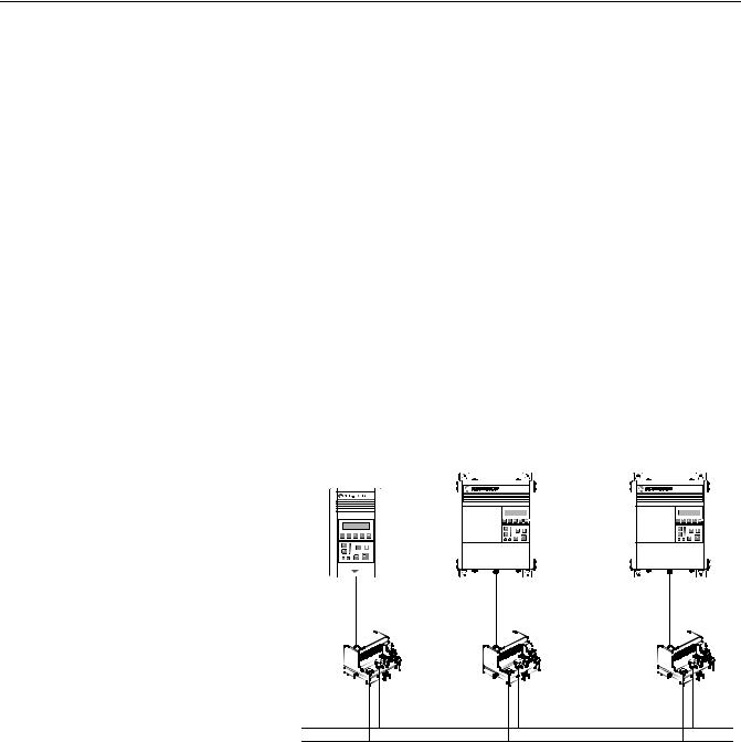
The 1203-CN1 ControlNet communications module provides an electronic communications interface between a ControlNet network and any single SCANport product.
Figure 1.1
Example of 1203-CN1 Modules Connecting SCANport Products to ControlNet
1336 IMPACT |
1336 PLUS |
1305 |
ControlNet
A SCANport cable connects the module to a SCANport product through a SCANport interface port on the SCANport product. One or two ControlNet cable taps connect the module to the ControlNet bus, depending on whether you are using non-redundant or redundant connections.
Publication 1203-5.13 – February, 2002
1-2 |
Overview |
|
The module translates the ControlNet messages into SCANport |
|
messages that can be understood by the SCANport product. Both |
|
scheduled I/O data and unscheduled messages can be transferred |
|
through the module. ControlNet capability enhances the functionality |
|
and usefulness of the connected product and lets you communicate |
|
with the SCANport product from any node on the ControlNet |
|
network. |
What Is ControlNet? |
ControlNet is a real-time, control-layer network providing high-speed |
|
transport of both scheduled time-critical I/O data and unscheduled |
|
messaging data, including upload/download of programming and |
|
configuration data and peer-to-peer messaging, on a single physical |
|
media link. Deterministic and repeatable, ControlNet’s high-speed (5 |
|
Mbps) control and data capabilities significantly enhance the size and |
|
speed of I/O data and messaging data transfers. |
|
Specifically, ControlNet provides: |
|
• Bandwidth for I/O, real-time interlocking, peer-to-peer |
|
messaging and programming—all on the same link, without |
|
impacting time-critical I/O. |
|
• Deterministic, repeatable performance for both discrete and |
|
process applications. |
|
• Multicast of both inputs and peer-to-peer data. |
|
• Fiber media, media redundancy and intrinsically safe options. |
|
• Simple and flexible installation requiring no special tools to |
|
install or tune the network. |
|
• Network access for any node. |
|
• Support for up to 99 nodes per subnet to help flatten architectures |
|
and support more distributed systems. |
|
• User-configured real-time remote analog updates for more |
|
flexibility and process capabilities. |
Publication 1203-5.13 – February, 2002
|
|
|
Overview |
|
1-3 |
||
SCANport Products |
Some SCANport products support one peripheral; others support up |
|
|||||
|
to six peripherals. The table below lists SCANport products, the |
||||||
|
number of peripherals each supports, and the minimum and |
||||||
|
maximum I/O words allowed between the product and module. |
||||||
|
|
|
|
|
|
|
|
|
|
|
Number of |
|
I/O Words |
||
|
|
Product |
Peripherals |
|
|
|
|
|
|
|
Minimum |
Maximum |
|||
|
|
|
Supported |
|
|||
|
|
|
|
|
|
|
|
|
1305 AC MICRO Drive |
5 |
|
0 |
10 |
|
|
|
1336 |
IMPACT™ Drive |
6 |
|
0 |
10 |
|
|
1336 PLUS AC Drive |
6 |
|
0 |
10 |
|
|
|
|
|
|
|
|
|
|
|
1336 |
PLUS II Drive |
6 |
|
0 |
10 |
|
|
1336 FORCE™ Drive |
6 |
|
0 |
10 |
|
|
|
1336 |
Line Regeneration Package |
2 |
|
0 |
2 |
|
|
|
|
|
|
|
|
|
|
1394 |
AC Mult-Axis Motion Control |
6 |
|
0 |
10 |
|
|
System |
|
|
||||
|
|
|
|
|
|
||
|
|
|
|
|
|
|
|
|
SMC Dialog Plus |
1 |
|
0 |
2 |
|
|
|
|
|
|
|
|
|
|
|
SMP-3 Smart Motor Protector |
2 |
|
0 |
2 |
|
|
|
|
|
|
|
|
|
|
|
1397 |
Digital DC Drive |
5 |
|
0 |
10 |
|
|
|
|
|
|
|
|
|
|
1557 |
Medium Voltage Drive |
5 |
|
0 |
10 |
|
|
|
|
|
|
|
|
|
|
2364 RGU DC Bus Regeneration |
6 |
|
0 |
10 |
|
|
|
Front End |
|
|
||||
|
|
|
|
|
|
||
|
|
|
|
|
|
|
|
Early versions of the 1305 AC MICRO Drive firmware may not support some types of communications.
Lower horsepower products may not support a sixth peripheral. Refer to your user manual to verify that your product supports a sixth peripheral.
Important: If you intend to use datalinks to communicate with and control your SCANport product, verify that your SCANport product supports datalinks before enabling them in the module.
Important: To connect multiple peripherals to a SCANport product, a port expander may be required. Refer to your product’s documentation for more information.
Publication 1203-5.13 – February, 2002
1-4 |
Overview |
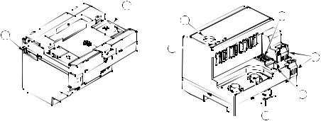
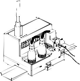
What Hardware Is Included? Figure 1.2 and the table below illustrate and list the main parts of the 1203-CN1 ControlNet communications module:
Figure 1.2
Parts of the Communications Module
1 
4 |
5 |
|
8 
3 
6 


 7
7 
 2
2 
Number |
Part |
Description |
|
|
|
1 |
DIN Rail Mount |
Securely attaches and electronically grounds the module to the DIN rail. |
|
|
|
2 |
ControlNet Coax |
Provide connections for ControlNet cable taps to allow either redundant or non-redundant |
|
Connections |
communications over the ControlNet network. |
|
|
|
3 |
Bi-Color LEDs |
Indicate the status of each ControlNet media channel, of the SCANport connection, and of |
|
|
the module. For more information, refer to Chapter 7, Troubleshooting. |
|
|
|
4 |
SCANport Connection |
Provides a standard SCANport 8-pin circular mini-DIN connector for the SCANport cable. |
|
|
|
5 |
ControlNet Node |
Displays the ControlNet node address for the module. Use the push buttons to set the |
|
Address Indicator |
address before applying power. |
|
|
|
6 |
+24V DC Power |
Provide for a +24V DC power supply connection. Multiple connections let you daisy chain |
|
Connections |
power through a group of modules placed close to each other. |
|
|
|
7 |
ControlNet Network |
Provides an RJ-45 connection for devices capable of communicating over ControlNet. The |
|
Access Port |
module as well as other operational network devices can be accessed. A ControlNet network |
|
|
access cable (1786-CP) and 1784-KTCX communication card, 1784-PCC communication |
|
|
card, or 1770-KFC communication interface are required to use this port. |
|
|
|
8 |
RS-232 Serial Port |
Provides a connection for terminals capable of RS-232 serial communications. This port can |
|
|
be used to edit the module’s parameters, download a file needed to perform a flash to the |
|
|
module’s operating code, and support devices that monitor and test the module. A 1203-SFC |
|
|
serial cable and a PC running a terminal emulation program or a VT100-compatible terminal |
|
|
are required to use this port. |
|
|
|
Publication 1203-5.13 – February, 2002
Overview |
1-5 |
Overview of Setting Up the
1203-CN1 Module
Required Tools and Equipment
To set up the 1203-CN1 module, you must perform the following tasks:
1.Install the module. Refer to Chapter 2, Installation.
2.If desired, configure the module’s parameters. Refer to Chapter 3,
Getting Started.
3.Configure the module on the ControlNet network. Refer to Chapter 4, Configuring a Controller to Communicate with the 1203-CN1 Module.
To install and configure a 1203-CN1 module, you need the following equipment:
•Grounding wrist strap (shipped with the module).
•1203-CN1 ControlNet communications module.
•35 x 7.5 mm DIN rail A (Allen-Bradley part number (199-DR1; 46277-3; EN 50022).
•1/8 in. (3.2 mm) flathead screwdriver.
•Blunt, pointed instrument (not pen or pencil) for setting the node address.
•Ohm meter.
•Appropriate cables for SCANport and ControlNet connections. Refer to Chapter 2, Installation, for more information.
•1203-SFC serial cable.
•Either a PC running a Windows™ terminal emulation program (e.g., HyperTerminal) or a VT100-compatible terminal.
•PC that is:
–Running RSNetWorx™, RSLogix5™, and RSLinx™.
–Connected to the ControlNet network using a 1784-KTCX card, 1784-PCC card, or 1770-KFC adapter.
Publication 1203-5.13 – February, 2002
1-6 |
Overview |
Notes:
Publication 1203-5.13 – February, 2002
Chapter 2
|
Installation |
|
Chapter Objectives |
Chapter 2 provides the information that you need to install the |
|
|
1203-CN1 ControlNet communications module. This information |
|
|
includes: |
|
|
• A list of tools and equipment needed for the installation. |
|
|
• A discussion of available cables for SCANport and ControlNet |
|
|
|
connections. |
|
• Instructions for installing the module. |
|
|
• Instructions for removing the module. |
|
|
After installing the module, refer to Chapter 3, Getting Started, for |
|
|
procedures on how to configuring the module’s parameters and refer |
|
|
to Chapter 4, Configuring a Controller to Communicate with the |
|
|
1203-CN1 Module, for information on configuring the module on the |
|
|
ControlNet network. |
|
Required Tools and Equipment |
To install your 1203-CN1 module, you will need the following tools |
|
|
and equipment: |
|
|
• |
Grounding wrist strap. |
|
• 1203-CN1 ControlNet communications module. |
|
|
• 35 x 7.5 mm DIN rail A (Allen-Bradley part number 199-DR1; |
|
|
|
46277-3; EN 50022). |
|
• 1/8 in. (3.2 mm) flathead screwdriver. |
|
|
• Blunt, pointed instrument (not pen or pencil) for setting the node |
|
|
|
address. |
|
• Appropriate cables for SCANport and ControlNet connections. |
|
|
|
Refer to the Selecting Cables section in this chapter. |
|
• |
Ohm meter. |
Selecting Cables |
To connect the 1203-CN1 module to the SCANport product and the |
|
|
ControlNet network, you must select an appropriate SCANport cable |
|
and one or two ControlNet cable tap(s). Use the following information to select appropriate cables for each connection.
Publication 1203-5.13 – February, 2002
2-2 |
Installation |
SCANport Cables
When selecting the SCANport cable to connect the module to the
SCANport product, you need to:
•Use an Allen-Bradley SCANport cable. Refer to the table below.
Male to Male Connection |
Male to Female Connection |
||
Length |
Catalog Number |
Length |
Catalog Number |
|
|
|
|
1/3 m |
1202-C03 |
1/3 m |
1202-H03 |
|
|
|
|
1 m |
1202-C10 |
1 m |
1202-H10 |
|
|
|
|
3 m |
1202-C30 |
3 m |
1202-H30 |
|
|
|
|
9 m |
1202-C90 |
9 m |
1202-H90 |
|
|
|
|
For most installations, a male-to-male connection on the cable is required.
•Do not exceed 10 meters (33 feet) of cable between the SCANport product and module.
•Keep SCANport cables away from high power cables to guard against introducing noise into your system.
ControlNet Cable Taps
A tap connects a node on the ControlNet network, such as a module, to the cable system via an integral 1 m (39.6 in.) drop cable. When selecting a tap to connect the module to the ControlNet network, you need to:
•Determine if your network uses a redundant media system. If so, you will need two taps.
•Use one or two Allen-Bradley tap(s). Refer to the table below.
Type |
Catalog Number |
|
|
Straight T-Tap |
1786-TPS |
|
|
Straight Y-Tap |
1786-TPYS |
|
|
Right-Angle T-Tap |
1786-TPR |
|
|
Right-Angle Y-Tap |
1786-TPYR |
|
|
For more information on ControlNet taps and ControlNet networks, refer to Publication 1786-6.2.1, ControlNet Cable System Planning and Installation Manual.
Publication 1203-5.13 – February, 2002

Installation |
2-3 |
Electrostatic Discharge
Precautions
Please read the following safety precautions carefully before installing the 1203-CN1 module
ATTENTION: The 1203-CN1 ControlNet communications module contains ESD (Electrostatic
! Discharge) sensitive parts. Static control precautions are required when installing, testing, or servicing this module. Device malfunction may occur if you do not follow ESD control procedures. If you are not familiar with static control procedures, refer to Allen-Bradley publication 8000-4.5.2, Guarding Against Electrostatic Damage, or other applicable ESD protection handbook.
Important: You must wear a grounding wrist strap that is properly grounded when you handle the 1203-CN1 module.
Publication 1203-5.13 – February, 2002
2-4 |
Installation |
Installing Your 1203-CN1 Module The following instructions explain how to physically install your 1203-CN1 module.
Important: To guard against device malfunction, you must wear a grounding wrist strap when installing the 1203-CN1 module.
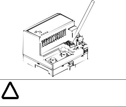
1.Set the module’s ControlNet node address by clicking the + or - button to the desired value for each digit.
Important: Each node on the ControlNet network must have a unique address.
Important: The node address must be set before power is applied because the module uses the node address it detects when it first receives power. To change a node address, you must set the new value and then remove and reapply power to or reset the module.
Figure 2.1
Setting the Module’s Node Address
ATTENTION: When setting the node address, use a blunt, pointed instrument. Do not use a pencil or pen ! because lead (graphite) or ink may damage the switch
assembly.
2. Ensure the DIN rail to which the module will be attached is connected to an earth ground.
Important: If EMC compliance is required, the DIN rail should be properly grounded inside a full metal enclosure. The enclosure should also be properly connected to an earth ground.
Publication 1203-5.13 – February, 2002
Installation |
2-5 |
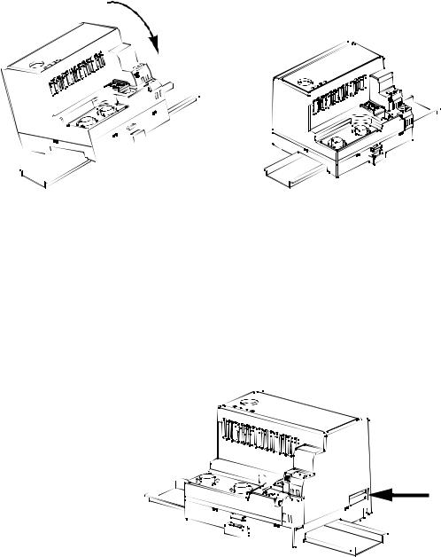
3.Hook the top lip of the module’s DIN rail mount onto the top of the DIN rail and then rotate the module onto the DIN rail. You will hear the module snap into a locked position.
Figure 2.2
Connecting the Module to the DIN Rail
4.Verify the module is correctly grounded to the DIN rail by using an Ohm meter to measure between:
•DIN rail’s earth ground.
•Metal shell in the module’s RS-232 serial port.
If the reading is greater than 2 Ohms, you must reconnect the module to the DIN rail, making sure it attaches securely.
Figure 2.3
Metal Shell of the Module’s RS-232 Serial Port
Publication 1203-5.13 – February, 2002

2-6 |
Installation |
5.Connect the SCANport cable to the SCANport product and the module.
To connect the cable to the module, align the pins on the cable with the holes in the SCANport connection and then insert the SCANport cable. The cable will click into a locked position.
Figure 2.4
Connecting the SCANport Cable to the Module
6.Connect the ControlNet cable tap(s) to the ControlNet media and the module.
To connect the cable tap(s) to the module, twist each onto the ControlNet Coax connection(s). You will hear the tap(s) click into a locked position.
Important: Make sure you connect the Channel A cable to the Channel A connection and the Channel B cable to the Channel B connection.
Figure 2.5
Connecting a Straight ControlNet Tap to the Module
Publication 1203-5.13 – February, 2002
Installation |
2-7 |
7.Connect a +24V power supply. If necessary, loosen the screw to insert the power supply connection and then re-tighten the screw.
Important: You can use the two sets of holes to daisy chain the power supply between multiple 1203-CN1 modules placed close together.
Figure 2.6
Connecting the Power Supply to the Module
 COMMON
 + 24 VDC
The module is now physically installed. Its SCANport and ControlNet LEDs are solid green, and its Module LED is flashing green. (If your module’s LEDs differ, refer to Chapter 7, Troubleshooting, for troubleshooting information.)
The flashing green Module LED means that the module is not yet able to provide an interface between the ControlNet network and the SCANport product. For it to do so, you must:
1.Configure, if necessary, the module by editing its parameters. Refer to Chapter 3, Getting Started.
2.Configure the controller on the ControlNet network to recognize and communicate with the module. Refer to Chapter 4,
Configuring a Controller to Communicate with the 1203-CN1 Module.
3.If desired, write a PLC Ladder Logic program to control the SCANport product. Refer to Chapter 5, PLC Ladder Logic Programming.
Important: The 1203-CN1 ControlNet communications module will not communicate over ControlNet without being connected to a SCANport product which is powered and operational.
Publication 1203-5.13 – February, 2002
2-8 |
Installation |
Removing the 1203-CN1 Module If you want to remove the 1203-CN1 module, you need to:
Important: To guard against device malfunction, you must wear a grounding wrist strap when removing the 1203-CN1 module.
1.Turn off the power supply to the module.
2.Disconnect all cables and the power supply from the module.
Important: To disconnect the SCANport cable, gently push in the cable and then pull it out.
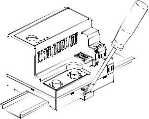
3.With a screw driver in the tab release, gently push its handle towards the module to release the connection tab, and then pull the module off of the DIN Rail.
Figure 2.7
Removing the Module from the DIN Rail
Publication 1203-5.13 – February, 2002

Chapter 3
Chapter Objectives
Factory-Default Settings for the 1203-CN1 Module’s Parameters
Getting Started
Chapter 3 provides information that you need to configure the 1203-CN1 ControlNet Communications module. This includes:
•Information on the 1203-CN1 module’s default setting.
•Equipment needed to make a serial connection to the module.
•Instructions on how to connect a PC running terminal emulation software or a VT100-compatible terminal to the module.
•Navigation techniques to use in the module’s software.
•Instructions for editing the module’s parameters.
•Instructions for displaying and clearing the module’s event queue.
•Instructions for displaying the modules I/O data.
•Instructions for displaying DF1 Protocol statistics.
•Instructions for viewing the module’s serial number.
•Instructions for performing a flash upgrade to the module.
The factory-default settings of the 1203-CN1 module enable the following functions:
•16-bit Logic Command/Status.
•16-bit Reference/Feedback.
•If the PLC is put into program mode or the network fails, the SCANport product will be faulted by the module.
•All datalinks are disabled.
•Baud rate is 9600.
If you wish to change any of these functions (e.g., Fault Configurable inputs) or add more functions (e.g., datalinks), you must edit the module’s parameters. To do so, refer to:
•Appendix B, 1203-CN1 Module Parameters, for detailed information about each of the module’s parameters.
•Instructions in this chapter on establishing a serial connection.
•Instructions in this chapter on how to edit the parameters.
Publication 1203-5.13 – February, 2002

3-2 |
Getting Started |
Required Tools and Equipment
Electrostatic Discharge
Precautions
To make a serial connection to the module, you need the following:
•Grounding wrist strap.
•1203-SFC serial cable.
•Either a PC running a Windows terminal emulation program (e.g., HyperTerminal) or a VT100-compatible terminal.
Please read the following safety precautions carefully before making a serial connection to the 1203-CN1 module.
ATTENTION: The 1203-CN1 ControlNet communications module contains ESD (Electrostatic
! Discharge) sensitive parts. Static control precautions are required when installing, testing, or servicing this module. Device malfunction may occur if you do not follow ESD control procedures. If you are not familiar with static control procedures, refer to Allen-Bradley publication 8000-4.5.2, Guarding Against Electrostatic Damage, or other applicable ESD protection handbook.
You must wear a grounding wrist strap that is properly grounded when you handle the 1203-CN1 module.
Establishing a Serial Connection The module’s software lets you do the following: with the 1203-CN1 Module
•Edit the module’s parameters.
•View its serial number.
•View its event queue.
•View its current I/O data.
•View DF1 statistics.
•Perform a flash upgrade.
To access its software, you must make a serial connection between the module and either a PC running terminal emulation software or a terminal. Refer to the following table:
If Using: |
Refer to Page |
|
|
PC running terminal emulation software |
3-3 |
|
|
VT100-compatible terminal |
3-7 |
|
|
DriveExplorer (v.101 or higher) software can now also be used on 1203-CN1s that are v2.001 or higher. Do not use DriveExplorer software with v1.xxx CN1s.
Publication 1203-5.13 – February, 2002
Loading...