


Texas Instruments TLV2393IPWR, TLV2393IPWLE, TLV2393IP, TLV2393IDR, TLV2393ID Datasheet
...
|
|
TLV1393, TLV1393Y, TLV2393, TLV2393Y |
||||||||
|
|
DUAL DIFFERENTIAL COMPARATORS |
||||||||
|
|
SLCS121A ± AUGUST 1993 ± REVISED APRIL 1994 |
||||||||
|
|
|
|
|
|
|
|
|
||
D Low-Voltage and Single-Supply Operation |
D, P, OR PW PACKAGE |
|||||||||
|
VCC = 2 V to 7 V |
|
|
|
(TOP VIEW) |
|
|
|||
|
|
|
|
|
|
|
|
|
|
|
D Common-Mode Voltage Range Includes |
1OUT |
|
|
1 |
8 |
|
|
VCC |
||
|
|
|
|
|||||||
|
Ground |
|
|
|
|
|||||
|
1IN ± |
|
|
2 |
7 |
|
|
2OUT |
||
|
Fast Response Time |
|
|
|
||||||
D |
1IN+ |
|
|
3 |
6 |
|
|
2IN ± |
||
|
450 ns Typ (TLV2393) |
GND |
|
|
4 |
5 |
|
|
2IN+ |
|
D |
Low Supply Current |
|
|
|
|
|
|
|
|
|
|
|
|
|
|
|
|
|
|
||
|
0.16 mA Typ (TLV1393) |
|
|
|
|
|
|
|
|
|
D Fully Specified at 3-V and 5-V Supply
Voltages
description
The TLV1393 and the TLV2393 are dual differential comparators built using a new Texas Instruments low-voltage, high-speed bipolar process. These devices have been specifically developed for low-voltage, single-supply applications. Their enhanced performance makes them excellent replacements for the LM393 in today's improved 3-V and 5-V system designs.
The TLV1393, with its typical supply current of only 0.16 mA, is ideal for low-power systems. Response time has also been improved to 0.7 μs. For higher-speed applications, the TLV2393 features excellent ac performance with a response time of just 0.45 μs, three times that of the LM393.
Package availability for these devices includes the TSSOP (thin-shrink small-outline package). With a maximum thickness of 1.1 mm and a package area that is 25% smaller than the standard surface-mount package, the TSSOP is ideal for high-density circuits, particularly in hand-held and portable equipment.
AVAILABLE OPTIONS
|
|
|
PACKAGED DEVICES |
|
|
CHIP FORM |
||
TA |
|
|
|
|
|
|
||
SUPPLY CURRENT |
RESPONSE TIME |
SMALL OUTLINE |
PLASTIC DIP |
TSSOP |
||||
(Y) |
||||||||
|
(TYP) |
(TYP) |
(D) |
(P) |
(PW)² |
|
||
±40°C to 105°C |
0.16 mA |
0.7 |
μs |
TLV1393ID |
TLV1393IP |
TLV1393IPWLE |
TLV1393Y |
|
1.1 mA |
0.45 |
μs |
TLV2393ID |
TLV2393IP |
TLV2393IPWLE |
TLV2393Y |
||
|
||||||||
|
|
|
|
|
|
|
|
|
² The PW packages are only available left-ended taped and reeled (e.g., TLV1393IPWLE).
symbol (each comparator)
IN+
OUT
IN ±
PRODUCTION DATA information is current as of publication date. Products conform to specifications per the terms of Texas Instruments standard warranty. Production processing does not necessarily include testing of all parameters.
Copyright 1994, Texas Instruments Incorporated
POST OFFICE BOX 655303 •DALLAS, TEXAS 75265 |
1 |
TLV1393, TLV1393Y, TLV2393, TLV2393Y
DUAL DIFFERENTIAL COMPARATORS
SLCS121A ± AUGUST 1993 ± REVISED APRIL 1994
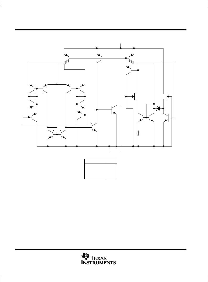
TLV1393, TLV1393Y equivalent schematic (each comparator)
VCC
IN +
IN ±
GND OUT
COMPONENT COUNT
Transistors |
44 |
Resistors |
1 |
Diodes |
7 |
Epi-FET |
2 |
2 |
POST OFFICE BOX 655303 •DALLAS, TEXAS 75265 |

TLV1393, TLV1393Y, TLV2393, TLV2393Y
DUAL DIFFERENTIAL COMPARATORS
SLCS121A ± AUGUST 1993 ± REVISED APRIL 1994
TLV2393, TLV2393Y equivalent schematic (each comparator)
VCC
IN +
IN ±
GND OUT
COMPONENT COUNT
Transistors |
44 |
Resistors |
1 |
Diodes |
7 |
Epi-FET |
2 |
POST OFFICE BOX 655303 •DALLAS, TEXAS 75265 |
3 |
TLV1393, TLV1393Y, TLV2393, TLV2393Y
DUAL DIFFERENTIAL COMPARATORS
SLCS121A ± AUGUST 1993 ± REVISED APRIL 1994
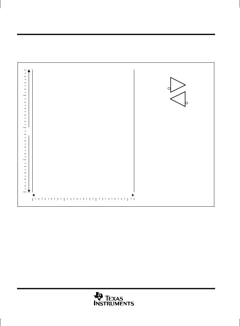
TLV1393Y chip information
This chip, when properly assembled, displays characteristics similar to the TLV1393. Thermal compression or ultrasonic bonding may be used on the doped-aluminum bonding pads. Chips may be mounted with conductive epoxy or a gold-silicon preform.
|
BONDING PAD ASSIGNMENTS |
|
|
|
|
|
|
|
|
|
|
|
|
|
(3) |
|
VCC |
|
|
|
|||
|
|
|
|
|
|
|
|||||
|
|
|
|
|
|
(8) |
|
|
|
||
(7) |
(6) |
1IN + |
+ |
|
|
|
|
|
|||
|
|
|
|
(1) |
1OUT |
||||||
|
|
|
|
||||||||
|
|
|
|
|
|
|
|
|
|||
|
|
1IN ± |
(2) |
± |
|
|
|
|
|||
|
|
|
|
|
|||||||
|
|
|
|
|
|
|
|||||
|
|
|
|
|
|
(5) |
|
||||
|
|
|
|
|
|||||||
|
|
|
|
|
+ |
2IN + |
|||||
|
|
2OUT |
(7) |
|
|
||||||
|
|
|
|
||||||||
|
|
|
|
|
|
|
|
|
|||
|
|
|
|
|
|
|
± |
(6) |
2IN ± |
||
|
|
|
|
|
|
|
|||||
|
|
|
|
|
|
|
|
||||
|
|
|
|
|
|
|
|
|
|||
|
|
|
|
|
|
|
|||||
|
|
|
|
|
|
|
(4) |
|
|
|
|
|
(5) |
|
|
|
|
GND |
|
|
|
||
|
|
|
|
|
|
|
|
|
|
|
|
(8) |
|
|
|
|
|
|
|
|
|
|
|
38
(1) |
|
|
|
|
|
|
|
(4) |
|
CHIP THICKNESS: 13 TYPICAL |
|
|
|
|
|
||
|
|
|
|
|
BONDING PADS: 3.54 × 3.54 MINIMUM |
|
|
|
|
|
TJmax = 150°C |
|
|
|
|
|
TOLERANCES ARE ± 10%. |
|
|
(3) |
|
ALL DIMENSIONS ARE IN MILS. |
|
(2) |
|
PIN (4) IS INTERNALLY CONNECTED |
|||
|
|
|
|||
|
|
|
|
|
|
|
|
|
|
|
TO BACKSIDE OF CHIP. |
|
|
|
|
|
|
|
|
32 |
|
|
|
|
|
|
|
|
|
4 |
POST OFFICE BOX 655303 •DALLAS, TEXAS 75265 |
TLV1393, TLV1393Y, TLV2393, TLV2393Y
DUAL DIFFERENTIAL COMPARATORS
SLCS121A ± AUGUST 1993 ± REVISED APRIL 1994
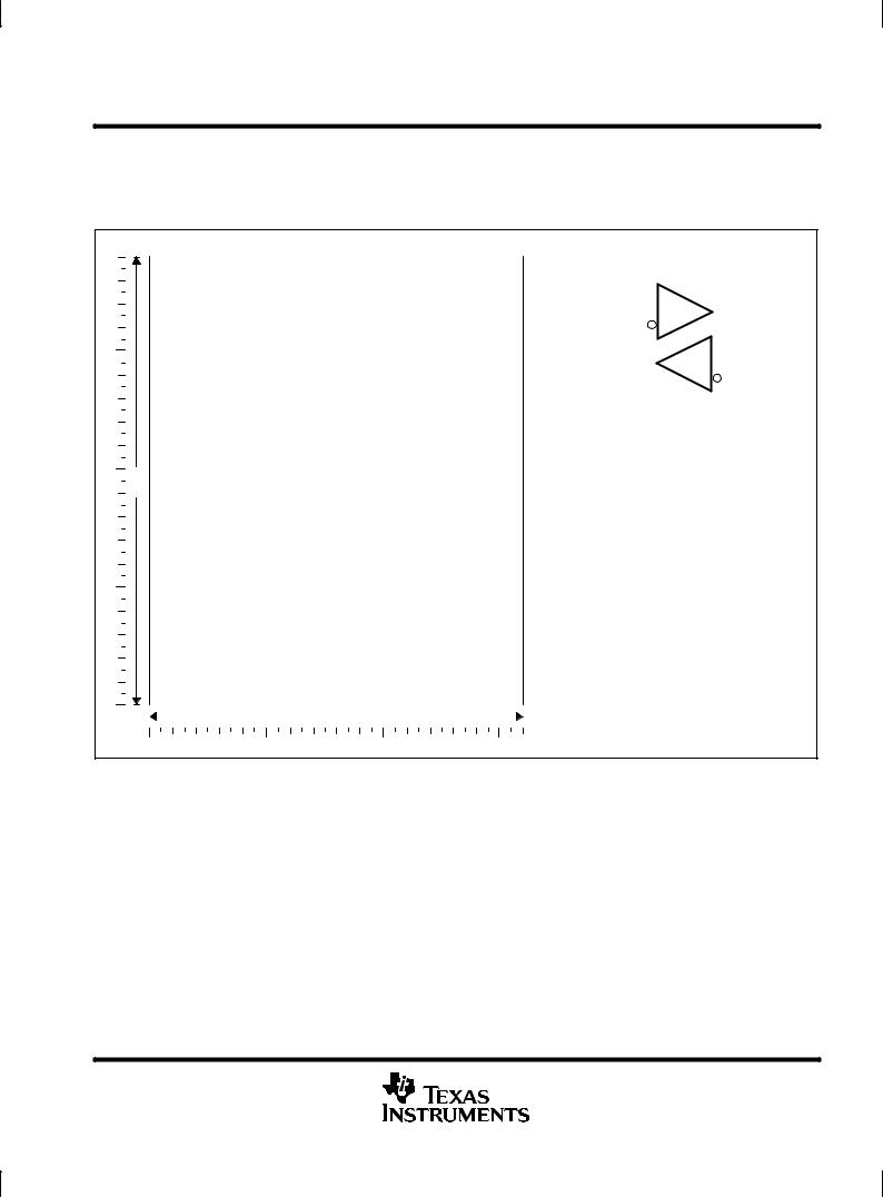
TLV2393Y chip information
This chip, when properly assembled, displays characteristics similar to the TLV2393. Thermal compression or ultrasonic bonding may be used on the doped-aluminum bonding pads. Chips may be mounted with conductive epoxy or a gold-silicon preform.
|
BONDING PAD ASSIGNMENTS |
|
|
|
|
|
|
|
|
|
|
|
|
|
(3) |
|
VCC |
|
|
|
|||
|
|
|
|
|
|
|
|||||
|
|
|
|
|
|
(8) |
|
|
|
||
(7) |
(6) |
1IN + |
+ |
|
|
|
|
|
|||
|
|
|
|
(1) |
1OUT |
||||||
|
|
|
|
||||||||
|
|
|
|
|
|
|
|
|
|||
|
|
1IN ± |
(2) |
± |
|
|
|
|
|||
|
|
|
|
|
|||||||
|
|
|
|
|
|
|
|||||
|
|
|
|
|
|
(5) |
|
||||
|
|
|
|
|
|||||||
|
|
|
|
|
+ |
2IN + |
|||||
|
|
2OUT |
(7) |
|
|
||||||
|
|
|
|
||||||||
|
|
|
|
|
|
|
|
|
|||
|
|
|
|
|
|
|
± |
(6) |
2IN ± |
||
|
|
|
|
|
|
|
|||||
|
|
|
|
|
|
|
|
||||
|
|
|
|
|
|
|
|
|
|||
|
|
|
|
|
|
|
|||||
|
|
|
|
|
|
|
(4) |
|
|
|
|
|
(5) |
|
|
|
|
GND |
|
|
|
||
|
|
|
|
|
|
|
|
|
|
|
|
(8) |
|
|
|
|
|
|
|
|
|
|
|
38
(1) |
|
|
|
|
|
|
|
(4) |
|
CHIP THICKNESS: 15 TYPICAL |
|
|
|
|
|
||
|
|
|
|
|
BONDING PADS: 3.6 × 3.6 MINIMUM |
|
|
|
|
|
TJmax = 150°C |
|
|
|
|
|
TOLERANCES ARE ± 10%. |
|
|
(3) |
|
ALL DIMENSIONS ARE IN MILS. |
|
(2) |
|
PIN (4) IS INTERNALLY CONNECTED |
|||
|
|
|
|||
|
|
|
|
|
|
|
|
|
|
|
TO BACKSIDE OF CHIP. |
|
|
|
|
|
|
|
|
32 |
|
|
|
|
|
|
|
|
|
POST OFFICE BOX 655303 •DALLAS, TEXAS 75265 |
5 |
 Loading...