


Texas Instruments TLC5510IPWR, TLC5510IPW, TLC5510INSR, TLC5510INS, TLC5510INSLE Datasheet
...TLC5510, TLC5510A 8-BIT HIGH-SPEED ANALOG-TO-DIGITAL CONVERTERS
SLAS095K ± SEPTEMBER 1994 ± REVISED MAY 1999
features
DAnalog Input Range
±TLC5510 . . . 2 V Full Scale
±TLC5510A . . . 4 V Full Scale
D8-Bit Resolution
DIntegral Linearity Error
±0.75 LSB Max (25°C)
±1 LSB Max (±20°C to 75°C)
DDifferential Linearity Error
±0.5 LSB Max (25°C)
±0.75 LSB Max (±20°C to 75°C)
DMaximum Conversion Rate
20 Mega-Samples per Second (MSPS) Max
description
D5-V Single-Supply Operation
DLow Power Consumption TLC5510 . . . 127.5 mW Typ TLC5510A . . . 150 mW Typ
(includes reference resistor dissipation)
DTLC5510 is Interchangeable With Sony CXD1175
applications
DDigital TV
DMedical Imaging
DVideo Conferencing
DHigh-Speed Data Conversion
DQAM Demodulators
PW OR NS PACKAGE²
(TOP VIEW)
The TLC5510 and TLC5510A are CMOS, 8-bit, 20 |
|
|
|
|
|
|
|
DGND |
MSPS analog-to-digital converters (ADCs) that |
|
OE |
|
|
1 |
24 |
|
|
DGND |
|
|
|
REFB |
||||
utilize a semiflash architecture. The TLC5510 and |
|
|
2 |
23 |
|
|||
TLC5510A operate with a single 5-V supply and |
D1(LSB) |
|
|
3 |
22 |
|
REFBS |
|
|
|
|
||||||
typically consume only 130 mW of power. |
|
D2 |
|
|
4 |
21 |
|
AGND |
|
|
|
|
|||||
Included is an internal sample-and-hold circuit, |
|
D3 |
|
|
5 |
20 |
|
AGND |
|
|
|
|
|||||
parallel outputs with high-impedance mode, and |
|
D4 |
|
|
6 |
19 |
|
ANALOG IN |
|
|
|
|
|||||
internal reference resistors. |
|
D5 |
|
|
7 |
18 |
|
VDDA |
|
|
|
|
|||||
|
|
|
|
|
|
|||
The semiflash architecture reduces power |
|
D6 |
|
|
8 |
17 |
|
REFT |
|
D7 |
|
|
9 |
16 |
|
REFTS |
|
consumption and die size compared to flash |
|
|
|
|
||||
D8(MSB) |
|
|
10 |
15 |
|
VDDA |
||
converters. By implementing the conversion in a |
|
|
|
|||||
|
|
|
||||||
2-step process, the number of comparators is |
VDDD |
|
|
11 |
14 |
|
VDDA |
|
|
|
|
||||||
significantly reduced. The latency of the data |
CLK |
|
|
12 |
13 |
|
VDDD |
|
|
|
|
||||||
output valid is 2.5 clocks. |
² Available in tape and reel only and ordered |
|||||||
The TLC5510 uses the three internal reference |
as the shown in the Available Options table |
|||||||
below. |
|
|
|
|
|
|
||
resistors to create a standard, 2-V, full-scale |
|
|
|
|
|
|
||
|
|
|
|
|
|
|
|
|
conversion range using VDDA. Only external jumpers are required to implement this option and eliminates the need for external reference resistors. The TLC5510A uses only the center internal resistor section with an externally applied 4-V reference such that a 4-V input signal can be used. Differential linearity is 0.5 LSB at 25°C and a maximum of 0.75 LSB over the full operating temperature range. Typical dynamic specifications include a differential gain of 1% and differential phase of 0.7 degrees.
The TLC5510 and TLC5510A are characterized for operation from ±20°C to 75°C.
|
|
AVAILABLE OPTIONS |
|
|
|
|
PACKAGE |
MAXIMUM FULL-SCALE |
|
TA |
|
|
|
|
|
|
SOP (NS) |
||
TSSOP (PW) |
|
INPUT VOLTAGE |
||
|
|
(TAPE AND REEL ONLY) |
||
|
|
|
|
|
|
|
|
|
|
±20°C to 75°C |
TLC5510IPW |
|
TLC5510INSLE |
2 V |
|
|
|
|
|
± |
|
TLC5510AINSLE |
4 V |
|
|
|
|||
Please be aware that an important notice concerning availability, standard warranty, and use in critical applications of Texas Instruments semiconductor products and disclaimers thereto appears at the end of this data sheet.
PRODUCTION DATA information is current as of publication date. Products conform to specifications per the terms of Texas Instruments standard warranty. Production processing does not necessarily include testing of all parameters.
Copyright 1999, Texas Instruments Incorporated
POST OFFICE BOX 655303 •DALLAS, TEXAS 75265 |
1 |

TLC5510, TLC5510A
8-BIT HIGH-SPEED ANALOG-TO-DIGITAL CONVERTERS
SLAS095K ± SEPTEMBER 1994 ± REVISED MAY 1999
functional block diagram
|
Resistor |
|
|
Reference |
|
|
Divider |
|
REFB |
|
|
|
270 Ω |
|
|
NOM |
|
REFT |
Lower Sampling |
|
Comparators |
||
REFBS |
||
(4-Bit) |
||
|
80 Ω |
|
|
NOM |
|
AGND |
|
|
AGND |
Lower Sampling |
|
|
Comparators |
|
VDDA |
(4-Bit) |
|
|
||
|
320 Ω |
|
REFTS |
NOM |
|
Upper Sampling |
||
ANALOG IN |
Comparators |
|
|
(4-Bit) |
|
CLK |
Clock |
|
Generator |
||
|
OE |
|
|
Lower Encoder |
D1(LSB) |
|
(4-Bit) |
||
D2 |
||
Lower Data |
||
Latch |
D3 |
|
|
||
|
D4 |
|
Lower Encoder |
|
|
(4-Bit) |
|
|
|
D5 |
|
Upper Data |
D6 |
|
Latch |
D7 |
|
Upper Encoder |
||
D8(MSB) |
||
(4-Bit) |
||
|
schematics of inputs and outputs |
|
|
EQUIVALENT OF ANALOG INPUT |
EQUIVALENT OF EACH DIGITAL INPUT |
EQUIVALENT OF EACH DIGITAL OUTPUT |
VDDA |
VDDD |
VDDD |
ANALOG IN |
OE, CLK |
D1 ± D8 |
|
||
AGND |
DGND |
DGND |
2 |
POST OFFICE BOX 655303 •DALLAS, TEXAS 75265 |

|
|
|
|
|
|
|
|
|
|
TLC5510, TLC5510A |
|
|
|
|
|
|
8-BIT HIGH-SPEED ANALOG-TO-DIGITAL CONVERTERS |
||||||
|
|
|
|
|
|
|
|
|
SLAS095K ± SEPTEMBER 1994 ± REVISED MAY 1999 |
||
|
|
|
|
|
|
|
|
|
|
|
|
|
|
|
|
|
Terminal Functions |
||||||
|
|
|
|
|
|
|
|
|
|
|
|
|
|
TERMINAL |
I/O |
|
|
|
DESCRIPTION |
|
|||
|
NAME |
NO. |
|
|
|
|
|||||
|
|
|
|
|
|
|
|
|
|||
|
|
|
|
|
|
|
|
|
|
|
|
|
AGND |
20, 21 |
|
Analog ground |
|
|
|
|
|||
|
|
|
|
|
|
|
|
|
|
|
|
|
ANALOG IN |
19 |
I |
Analog input |
|
|
|
|
|||
|
|
|
|
|
|
|
|
|
|
|
|
|
CLK |
12 |
I |
Clock input |
|
|
|
|
|||
|
|
|
|
|
|
|
|
|
|
|
|
|
DGND |
2, 24 |
|
Digital ground |
|
|
|
|
|||
|
|
|
|
|
|
|
|
|
|
|
|
|
D1 ± D8 |
3 ± 10 |
O |
Digital data out. D1 = LSB, D8 = MSB |
|
|
|
|
|||
|
|
|
|
|
|
|
|
|
|
||
|
|
|
1 |
I |
Output enable. When |
|
= low, data is enabled. When |
|
= high, D1 ± D8 is in high-impedance state. |
|
|
|
OE |
|
OE |
OE |
|
||||||
|
|
|
|
|
|
|
|
|
|||
|
VDDA |
14, 15, 18 |
|
Analog supply voltage |
|
|
|
|
|||
|
VDDD |
11, 13 |
|
Digital supply voltage |
|
|
|
|
|||
|
REFB |
23 |
I |
Reference voltage in bottom |
|
|
|
|
|||
|
|
|
|
|
|
||||||
|
REFBS |
22 |
|
Reference voltage in bottom. When using the TLC5510 internal voltage divider to generate a nominal 2-V |
|
||||||
|
|
|
|
|
reference, REFBS is shorted to REFB (see Figure 3). When using the TLC5510A, REFBS is connected to |
|
|||||
|
|
|
|
|
ground. |
|
|
|
|
||
|
|
|
|
|
|
|
|
|
|||
|
REFT |
17 |
I |
Reference voltage in top |
|
|
|
|
|||
|
|
|
|
|
|
||||||
|
REFTS |
16 |
|
Reference voltage in top. When using the TLC5510 internal voltage divider to generate a nominal 2-V |
|
||||||
|
|
|
|
|
reference, REFTS is shorted to REFT (see Figure 3). When using the TLC5510A, REFTS is connected to |
|
|||||
|
|
|
|
|
VDDA. |
|
|
|
|
||
absolute maximum ratings² |
|
|
|
|
|||||||
|
|
Supply voltage, VDDA, VDDD . . . . . . . . . . . . . . . . . . . . . . . . . |
. . . . . . . . . |
. . |
. . . . . . . . . . . . . . . . . . . . . . . . . . . . . 7 V |
||||||
|
|
Reference voltage input range, VREFT, VREFB . . . . . . . . . . . |
. . . . . . . . |
. . |
. . . . . . . . . . . . . . . . . . AGND to VDDA |
||||||
|
|
Analog input voltage range, VI(ANLG) . . . . . . . . . . . . . . . . . . . |
. . . . . . . . |
. . |
. . . . . . . . . . . . . . . . . . AGND to VDDA |
||||||
|
|
Digital input voltage range, VI(DGTL) . . . . . . . . . . . . . . . . . . . . |
. . . . . . . . |
. . |
. . . . . . . . . . . . . . . . . . DGND to VDDD |
||||||
|
|
Digital output voltage range, VO(DGTL) . . . . . . . . . . . . . . . . . |
. . . . . . . . |
. . |
. . . . . . . . . . . . . . . . . . DGND to VDDD |
||||||
|
|
Operating free-air temperature range, TA . . . . . . . . . . . . . . . |
. . . . . . . . |
. . |
. . . . . . . . . . . . . . . . . . . ±20°C to 75°C |
||||||
|
|
Storage temperature range, Tstg . . . . . . . . . . . . . . . . . . . . . . . |
. . . . . . . . |
. . |
. . . . . . . . . . . . . . . . . . ±55°C to 150°C |
||||||
²Stresses beyond those listed under ªabsolute maximum ratingsº may cause permanent damage to the device. These are stress ratings only, and functional operation of the device at these or any other conditions beyond those indicated under ªrecommended operating conditionsº is not implied. Exposure to absolute-maximum-rated conditions for extended periods may affect device reliability.
recommended operating conditions
|
|
MIN |
NOM |
MAX |
UNIT |
|
|
|
|
|
|
|
|
|
VDDA ± AGND |
4.75 |
5 |
5.25 |
V |
|
Supply voltage |
VDDD ± AGND |
4.75 |
5 |
5.25 |
||
|
||||||
|
AGND ± DGND |
± 100 |
0 |
100 |
mV |
|
|
|
|
|
|
|
|
Reference input voltage (top), Vref(T)³ |
TLC5510A |
VREFB+2 |
|
4 |
V |
|
Reference input voltage (bottom), Vref(B)³ |
TLC5510A |
0 |
|
VREFT± 4 |
V |
|
Analog input voltage range, VI(ANLG) |
|
VREFB |
|
VREFT |
V |
|
High-level input voltage, VIH |
|
4 |
|
|
V |
|
Low-level input voltage, VIL |
|
|
|
1 |
V |
|
Pulse duration, clock high, tw(H) (see Figure 1) |
|
25 |
|
|
ns |
|
Pulse duration, clock low, tw(L) (see Figure 1) |
|
25 |
|
|
ns |
³The reference voltage levels for the TLC5510 are derived through an internal resistor divider between VDDA and ground and therefore are not derived from a separate external voltage source (see the electrical characteristics and text). For the 4 V input range of the TLC5510A, the reference voltage is externally applied across the center divider resistor.
POST OFFICE BOX 655303 •DALLAS, TEXAS 75265 |
3 |
TLC5510, TLC5510A
8-BIT HIGH-SPEED ANALOG-TO-DIGITAL CONVERTERS
SLAS095K ± SEPTEMBER 1994 ± REVISED MAY 1999
electrical characteristics at VDD = 5 V, VREFT = 2.5 V, VREFB = 0.5 V, f(CLK) = 20 MHz, TA = 25°C (unless otherwise noted)
digital I/O
|
PARAMETER |
|
|
|
TEST CONDITIONS² |
MIN TYP MAX |
UNIT |
||
IIH |
High-level input current |
VDD = MAX, |
VIH = VDD |
|
5 |
μA |
|||
IIL |
Low-level input current |
VDD = MAX, |
VIL = 0 |
|
5 |
||||
|
|
||||||||
IOH |
High-level output current |
|
VDD = MIN, |
VOH = VDD ± 0.5 V |
± 1.5 |
|
|||
|
OE |
= GND, |
mA |
||||||
|
|
|
|
|
|
|
|
||
IOL |
Low-level output current |
OE = GND, |
VDD = MIN, |
VOL = 0.4 V |
2.5 |
||||
|
|||||||||
|
High-level high-impedance-state |
|
|
|
|
|
|
|
|
IOZH |
OE = VDD, |
VDD = MAX |
VOH = VDD |
16 |
|
||||
output leakage current |
|
||||||||
|
|
|
|
|
|
|
μA |
||
|
|
|
|
|
|
|
|
||
|
Low-level high-impedance-state |
|
|
|
|
|
|
||
|
|
|
|
|
|
|
|
||
IOZL |
OE = VDD, |
VDD = MIN |
VOL = 0 |
16 |
|
||||
output leakage current |
|
||||||||
|
|
|
|
|
|
|
|
||
|
|
|
|
|
|
|
|
|
|
² Conditions marked MIN or MAX are as stated in recommended operating conditions.
power
|
PARAMETER |
|
TEST CONDITIONS² |
MIN |
TYP |
MAX |
UNIT |
|
IDD |
Supply current |
f(CLK) = 20 MHz, National Television System Committee (NTSC) |
|
18 |
27 |
mA |
||
ramp wave input, reference resistor dissipation is separate |
|
|||||||
|
|
|
|
|
|
|||
|
|
|
|
|
|
|
|
|
Iref |
Reference voltage current |
TLC5510 |
|
Vref = REFT ± REFB = 2 V |
5.2 |
7.5 |
10.5 |
mA |
TLC5510A |
|
Vref = REFT ± REFB = 4 V |
10.4 |
15 |
21 |
mA |
||
|
|
|
||||||
² Conditions marked MIN or MAX are as stated in recommended operating conditions.
static performance
|
PARAMETER |
|
|
TEST CONDITIONS² |
|
MIN |
TYP |
MAX |
UNIT |
||||
|
Self-bias (1), at REFB |
Short REFB to REFBS, |
Short REFT to REFTS |
0.57 |
0.61 |
|
0.65 |
|
|||||
|
|
|
|
|
|
|
|
V |
|||||
|
Self-bias (2), REFT ± REFB |
1.9 |
2.02 |
|
2.15 |
||||||||
|
|
|
|
|
|
|
|||||||
|
|
|
|
|
|
|
|
|
|
||||
|
Self-bias (3), at REFT |
Short REFB to AGND, |
Short REFT to REFTS |
2.18 |
2.29 |
|
2.4 |
|
|||||
|
|
|
|
|
|
|
|
|
|
|
|||
Rref |
Reference voltage resistor |
Between REFT and REFB |
|
190 |
270 |
|
350 |
Ω |
|||||
Ci |
Analog input capacitance |
VI(ANLG) = 1.5 V + 0.07 Vrms |
|
|
16 |
|
|
|
pF |
||||
|
|
TLC5510 |
f |
(CLK) |
= 20 MHz, |
TA = 25°C |
|
|
± 0.4 |
± 0.75 |
|
||
|
|
V = 0.5 V to 2.5 V |
° |
° |
|
|
|
± |
1 |
|
|||
|
|
|
|
|
|
|
|||||||
|
Integral nonlinearity (INL) |
|
|
I |
|
TA = ± 20 C to 75 C |
|
|
|
|
|
||
|
TLC5510A |
f |
(CLK) |
= 20 MHz, |
TA = 25°C |
|
|
± 0.4 |
± 0.75 |
|
|||
|
|
|
|
|
|||||||||
|
|
V = 0 to 4 V |
° |
° |
|
|
|
± |
1 |
|
|||
|
|
|
|
|
|
|
|||||||
|
|
|
|
I |
|
TA = ± 20 C to 75 C |
|
|
|
|
LSB |
||
|
|
TLC5510 |
f |
(CLK) |
= 20 MHz, |
TA = 25°C |
|
|
± 0.3 |
|
± 0.5 |
||
|
|
|
|
|
|
||||||||
|
|
V = 0.5 V to 2.5 V |
° |
° |
|
|
± |
0.75 |
|
||||
|
|
|
|
|
|
||||||||
|
Differential nonlinearity (DNL) |
|
|
I |
|
TA = ± 20 C to 75 C |
|
|
|
|
|||
|
TLC5510A |
f |
(CLK) |
= 20 MHz, |
TA = 25°C |
|
|
± 0.3 |
|
± 0.5 |
|
||
|
|
|
|
|
|
||||||||
|
|
V = 0 to 4 V |
° |
° |
|
|
± |
0.75 |
|
||||
|
|
|
|
|
|
||||||||
|
|
|
|
I |
|
TA = ± 20 C to 75 C |
|
|
|
|
|||
EZS |
Zero-scale error |
TLC5510 |
Vref = REFT ± REFB = 2 V |
|
± 18 |
± 43 |
|
± 68 |
mV |
||||
TLC5510A |
Vref= REFT ± REFB = 4 V |
|
± 36 |
± 86 |
± 136 |
mV |
|||||||
|
|
|
|||||||||||
EFS |
Full-scale error |
TLC5510 |
Vref = REFT ± REFB = 2 V |
|
± 20 |
0 |
|
20 |
mV |
||||
TLC5510A |
Vref = REFT ± REFB = 4 V |
|
± 40 |
0 |
|
40 |
mV |
||||||
|
|
|
|
||||||||||
² Conditions marked MIN or MAX are as stated in recommended operating conditions.
4 |
POST OFFICE BOX 655303 •DALLAS, TEXAS 75265 |
TLC5510, TLC5510A 8-BIT HIGH-SPEED ANALOG-TO-DIGITAL CONVERTERS
SLAS095K ± SEPTEMBER 1994 ± REVISED MAY 1999
operating characteristics at VDD = 5 V, VREFT = 2.5 V, VREFB = 0.5 V, f(CLK) = 20 MHz, TA = 25°C (unless otherwise noted)
|
PARAMETER |
TEST CONDITIONS |
MIN TYP |
MAX |
UNIT |
||||||
|
|
|
|
|
|
|
|
|
|
|
|
fconv |
Maximum conversion rate |
TLC5510 |
fI = 1-kHz ramp |
VI(ANLG) = 0.5 V ± 2.5 V |
|
20 |
MSPS |
||||
TLC5510A |
VI(ANLG) = 0 V ± 4 V |
|
20 |
MSPS |
|||||||
|
|
|
|
|
|
|
|
||||
BW |
Analog input bandwidth |
At ± 1 dB |
|
14 |
|
MHz |
|||||
|
|
|
|
|
|
|
|
|
|
||
td(D) |
Digital output delay time |
CL ≤ 10 pF (see Note 1 and Figure 1) |
18 |
30 |
ns |
||||||
|
Differential gain |
NTSC 40 Institute of Radio Engineers (IRE) |
1% |
|
|
||||||
|
Differential phase |
modulation wave, |
fconv = 14.3 MSPS |
0.7 |
|
degrees |
|||||
tAJ |
Aperture jitter time |
|
|
30 |
|
ps |
|||||
td(s) |
Sampling delay time |
|
|
4 |
|
ns |
|||||
ten |
Enable time, |
|
|
↓ to valid data |
CL = 10 pF |
|
5 |
|
ns |
||
OE |
|
|
|||||||||
tdis |
Disable time, |
|
|
↑ to high impedance |
CL = 10 pF |
|
7 |
|
ns |
||
OE |
|
|
|||||||||
|
|
|
|
|
|
|
Input tone = 1 MHz |
TA = 25°C |
45 |
|
|
|
|
|
|
|
|
|
Full range |
43 |
|
|
|
|
|
|
|
|
|
|
|
|
|
||
|
|
|
|
|
|
|
|
|
|
|
|
|
|
|
|
|
|
|
Input tone = 3 MHz |
TA = 25°C |
45 |
|
|
|
Spurious free dynamic range (SFDR) |
Full range |
46 |
|
dB |
||||||
|
|
|
|||||||||
|
|
|
|
|
|||||||
|
Input tone = 6 MHz |
TA = 25°C |
43 |
|
|||||||
|
|
|
|
|
|
|
|
|
|||
|
|
|
|
|
|
|
Full range |
42 |
|
|
|
|
|
|
|
|
|
|
|
|
|
||
|
|
|
|
|
|
|
|
|
|
|
|
|
|
|
|
|
|
|
Input tone = 10 MHz |
TA = 25°C |
39 |
|
|
|
|
|
|
|
|
|
Full range |
39 |
|
|
|
|
|
|
|
|
|
|
|
|
|
||
|
|
|
|
|
|
|
|
|
|
|
|
SNR |
Signal-to-noise ratio |
TA = 25°C |
|
46 |
|
dB |
|||||
Full range |
|
44 |
|
||||||||
|
|
|
|
|
|
|
|
|
|
||
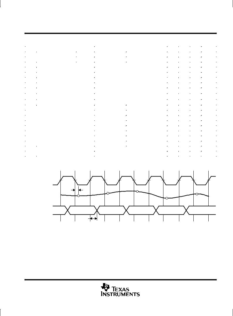
NOTE 1: CL includes probe and jig capacitance.
tw(H)  tw(L)
tw(L)
CLK (clock)
ANALOG IN |
td(s) |
|
|
|
|
|
|
N + 1 |
N + 2 |
|
|
||
(input signal) |
N |
|
N + 4 |
|||
|
|
|||||
|
|
N + 3 |
||||
|
|
|
|
|||
|
|
|
|
|
||
D1 ± D8 |
N ± 3 |
N ± 2 |
N ± 1 |
N |
N + 1 |
|
(output data) |
||||||
|
|
|
|
|
||
|
td(D) |
|
|
|
|
Figure 1. I/O Timing Diagram
POST OFFICE BOX 655303 •DALLAS, TEXAS 75265 |
5 |
 Loading...