


=3 =
#
!
4 4 4 4 4 4
# " 38 =
+( (37,2/(06 '(5&4,%(' %(.19 5+17.' %( ,056$..(' 10.; %; 37$.,),(' (.(&64,&$. /$,06(0$0&( 2(45100(. )$/,.,$4 9,6+ 6+( &105647&6,10 $0' 12(4$6,10 1) 6+( (37,2/(06 $0' 6+( +$<$4'5 ,081.8('
! ! ' F % " "
! " ! ! S " !
! # ! ! ! " ! ! "% & ! ! ! $
# S " ! !
" & !
,*74( +4((= +$5( ,0 $- .75 .(: $- .75(8(45,0* ,6
F % " " ! $
! ! & 0 4(8(45,0* $22.,&$6,105 6+( '4,8( /756 %( $5574(' 61 &1/( 61 $ 4(56 ! # ! ! " I ! !
!& ! ! ! # " ! "
$! ! " ! ! ! ! !
,*74( (8(45,0* ,6 056$..(' 0 7:,.,$4;$0(.
! $ ! !' ! $ " ! " "! ! ! " ! " ! &
$ # ! %! "
INST LL TION
W RNIN
OR TT MPTIN TO INST LL TH MIN9 P K PLUS L XP K PLUS MO I I TION KITIS ONN T N LO K OUT LL SOUR S O IN OMIN POW R TO TH ONTROLL R
1 Open the faceplate and let it hang down
2 Remove fuse circuit breaker mounting plate from auxiliary panel by removing three screws
3 Mount contactor to auxiliary chassis on 3:10 HP 230VAC units Use the two taptites provided On 15:20 HP @ 230VAC and 3:40 HP @ 460VAC units use four taptites and four flat washers Refer to figures 3 and 4
|
W |
R V |
T PTIT |
|
|
MOUNTIN |
|||
|
|
|
|
|
|
|
|
|
S R WS |
|
|
|
|
R V RSIN |
S |
|
|
|
ONT TOR |
|
|
|
|
|
L |
|
|
|
|
ROM |
|
|
|
|
T RMIN L O R |
|
L L |
|
|
|
H RN SS TO R UL TOR |
|
||
|
PRINT IR UIT MO UL |
|
||
|
||||
igure 3 39 HP @ 3 V Reversi0g Kit |
||||
|
M1u0ti0g L1cati10s |
|
||
|
|
|
|
|
|
|
L L |
PILOT |
|
US |
|
US R L Y P |
||
|
|
|||
R |
|
|
R |
IN IN |
|
|
|
||
|
|
|
|
HMS |
|
|
|
|
R V RSIN |
|
|
|
|
ONT TOR |
|
W |
R V |
T PTIT |
|
|
|
|
|
|
|
|
|
|
MOUNTIN |
|
|
|
|
S R WS |
S |
|
|
|
H RN SS TO |
US |
|
|
R UL TOR |
|
L |
|
|
||
ROM |
R |
US |
|
IR UIT |
T RMIN L |
|
R |
|
MO UL |
O R |
|
|
|
|
|
|
|
|
|
igure 4 Reversi0g Kit M1u0ti0g L1cati109 HP @ 3 V 394 HP @ 46 V
|
S |
|
ILT R |
|
|
P ITOR |
|
|
JUMP R |
||
|
|
||
|
|
JUMP R |
|
47 |
|
|
|
JUMP R |
S |
H RN SS |
|
|
TO |
|
|
|
TO |
R V RSIN |
|
|
R UL TOR |
||
JUMP R |
T RMIN L |
MO UL |
ONT TOR |
|
O R |
|
|
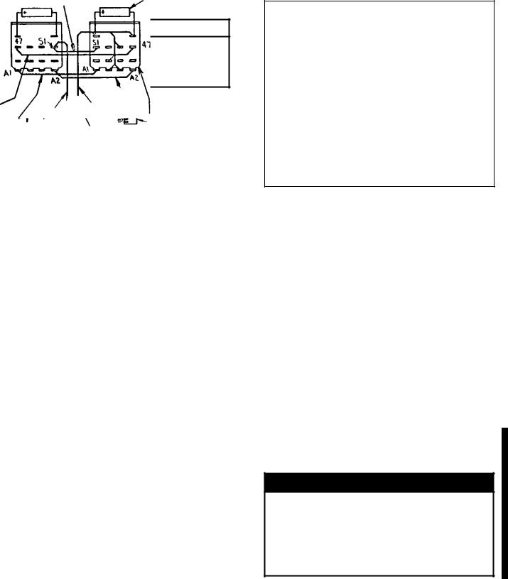
igure I0ter0a. Ju/2er 100ecti10 f1r 39 HP @ 3 V Reversi0g 22.icati10
4 39 HP 3 V 10.y Connect jumpers S1 47 A1 and A2 from forward contactor to reversing contactor as shown Refer to figure 5 Skip to step 7
5 .. 1ther rati0gs Connect bus bar S1 47 A1 and A2 from forward contactor to reversing contactor as shown Refer to figure 4
6 Mount pilot relay printed circuit card to auxiliary chassis using two binding HMS and star washers See figure 4 Connect leads 188:189 from pilot relay card to terminal board on forward pilot relay card mounted on left side of auxiliary panel
7 Mount label in corresponding position See figures 3 and 4
8 Connectharness from contactor 3:10 hp @ 230VAC units or pilot relay to Regulator Printed Circuit module terminal 139
9 If an optional Tachometer Feedback KitM N 14C221 is used locate jumpers J1 and J2 on the Tachometer Module Refer to figures 6 and 7 Clip out and discard these jumpers
N R
WH N R V RSIN ONT TOR IS INST LL OR OR NY R SON TH T HOM T R OUTPUT VOLT IS R V RS JUMP RS JN J ON TH T HOM T R K KIT MUST R MOV R R L SS O TH TYP T HOM T R US P RSON L INJURY M Y R SULT I THIS PRO UR IS NOT OLLOW
2
 Loading...