


Hardware Reference, Installation, and Troubleshooting Manual D2-3411-8
LiquiFlo AC Power Modules
Version 6.4

Important User Information
Solid-state equipment has operational characteristics differing from those of electromechanical equipment. Safety Guidelines for the Application, Installation and Maintenance of Solid State Controls (publication SGI-1.1 available from your local Rockwell Automation sales office or online at http://www.rockwellautomation.com/literature/) describes some important differences between solid-state equipment and hard-wired electromechanical devices. Because of this difference, and also because of the wide variety of uses for solid-state equipment, all persons responsible for applying this equipment must satisfy themselves that each intended application of this equipment is acceptable.
In no event will Rockwell Automation, Inc. be responsible or liable for indirect or consequential damages resulting from the use or application of this equipment.
The examples and diagrams in this manual are included solely for illustrative purposes. Because of the many variables and requirements associated with any particular installation, Rockwell Automation, Inc. cannot assume responsibility or liability for actual use based on the examples and diagrams.
No patent liability is assumed by Rockwell Automation, Inc. with respect to use of information, circuits, equipment, or software described in this manual.
Reproduction of the contents of this manual, in whole or in part, without written permission of Rockwell Automation, Inc., is prohibited.
Throughout this manual, when necessary, we use notes to make you aware of safety considerations.
WARNING: Identifies information about practices or circumstances that can cause an explosion in a hazardous environment, which may lead to personal injury or death, property damage, or economic loss.
ATTENTION: Identifies information about practices or circumstances that can lead to personal injury or death, property damage, or economic loss. Attentions help you identify a hazard, avoid a hazard, and recognize the consequence.
SHOCK HAZARD: Labels may be on or inside the equipment, for example, a drive or motor, to alert people that dangerous voltage may be present.
BURN HAZARD: Labels may be on or inside the equipment, for example, a drive or motor, to alert people that surfaces may reach dangerous temperatures.
ARC FLASH HAZARD: Labels may be on or inside the equipment, for example, a motor control center, to alert people to potential Arc Flash. Arc Flash will cause severe injury or death. Wear proper Personal Protective Equipment (PPE). Follow ALL Regulatory requirements for safe work practices and for Personal Protective Equipment (PPE).
IMPORTANT Identifies information that is critical for successful application and understanding of the product.
Allen-Bradley, Rockwell Software, Rockwell Automation, and TechConnect are trademarks of Rockwell Automation, Inc.
Trademarks not belonging to Rockwell Automation are property of their respective companies.

CONTENTS
Chapter 1 |
|
|
|
Introduction |
|
||
1.1 |
Related Publications ........................................................................................ |
1-1 |
|
1.2 |
Getting Assistance from Reliance Electric....................................................... |
1-1 |
|
Chapter 2 |
|
|
|
About the Drive |
|
||
2.1 |
Identifying the Drive by Model Number ........................................................... |
2-1 |
|
2.2 |
Enclosure Ratings ........................................................................................... |
2-2 |
|
2.3 |
B-Frame LiquiFlo Drive Component Locations................................................ |
2-2 |
|
2.4 |
C-Frame LiquiFlo Drive Component Locations ............................................... |
2-4 |
|
2.5 |
D-Frame LiquiFlo Drive Component Locations ............................................... |
2-6 |
|
2.6 |
Regulator Board Description ........................................................................... |
2-8 |
|
|
2.6.1 Jumper Locations and Settings ........................................................... |
2-10 |
|
|
|
2.6.1.1 Setting the Analog Input Speed Reference Jumper (J4) ...... |
2-10 |
|
|
2.6.1.2 Setting the Analog Output Jumper (J17)............................... |
2-11 |
|
2.6.2 Wiring the Regulator Board Terminal Strip.......................................... |
2-12 |
|
|
2.6.3 |
RS-232 Communication Port............................................................... |
2-13 |
|
2.6.4 |
RMI Board Connector ......................................................................... |
2-13 |
|
2.6.5 Operator Interface Module Connector................................................. |
2-14 |
|
|
2.6.6 |
Keypad/Display ................................................................................... |
2-14 |
2.7 |
RMI Board Description .................................................................................. |
2-15 |
|
|
2.7.1 |
Digital Inputs ....................................................................................... |
2-15 |
|
2.7.2 |
Digital Outputs..................................................................................... |
2-15 |
|
2.7.3 |
Relay Outputs ..................................................................................... |
2-15 |
|
2.7.4 |
Analog Input ........................................................................................ |
2-15 |
|
2.7.5 |
Analog Outputs ................................................................................... |
2-15 |
|
2.7.6 |
Frequency Input .................................................................................. |
2-15 |
|
2.7.7 Wiring the RMI Board Terminal Strip................................................... |
2-16 |
|
2.8 |
Optional Equipment ....................................................................................... |
2-17 |
|
Chapter 3 |
|
|
|
Planning the Installation |
|
||
3.1 |
General Requirements for the Installation Site ................................................ |
3-1 |
|
|
3.1.1 Making Sure Environmental Conditions are Met ................................... |
3-1 |
|
|
3.1.2 Determining Total Area Required Based on Drive Dimensions ............ |
3-2 |
|
|
3.1.3 Verifying the Site Provides for Recommended Air Flow Clearances .... |
3-6 |
|
|
3.1.4 Verifying Power Module Input Ratings Match Supplied Power ............. |
3-6 |
|
3.2 |
Wiring Requirements for the Drive .................................................................. |
3-6 |
|
|
3.2.1 Meeting Terminal Strip Input and Output Specifications ....................... |
3-6 |
|
|
3.2.2 Determining Wire Size Requirements ................................................... |
3-6 |
|
|
|
3.2.2.1 Conduit Entry Opening Sizes.................................................. |
3-6 |
|
|
3.2.2.2 Recommended Power Wire Sizes .......................................... |
3-6 |
|
|
3.2.2.3 Recommended Control and Signal Wire Sizes ....................... |
3-7 |
|
|
3.2.2.4 Recommended Motor Lead Lengths....................................... |
3-8 |
|
|
3.2.2.5 Recommended Serial Communication Cable Lengths ........... |
3-8 |
|
3.2.3 Selecting Input Line Branch Circuit Fuses ............................................ |
3-8 |
|
|
3.2.4 Meeting Encoder Specifications (FVC Regulation Only)....................... |
3-9 |
|
|
|
3.2.4.1 Encoder Wiring Guidelines ..................................................... |
3-9 |
|
3.2.5 Verifying Power Module Output Current Rating Is |
|
|
|
|
Greater Than Motor Full Load Amps..................................................... |
3-9 |
Contents |
I |
Chapter 4 |
|
|
|
Mounting the Drive, Grounding, and Finding Wire Routing Locations |
|
||
4.1 |
Lifting and Mounting the Drive ......................................................................... |
4-1 |
|
|
4.1.1 Verifying the Drive’s Watts Loss Rating................................................. |
4-2 |
|
4.2 |
Determining Input, Motor Output, Ground, and Control Wire |
|
|
|
Routing for the Drive ........................................................................................ |
4-2 |
|
4.3 |
Installing the DC Bus Reactor Fan (C-Frame Drives Only).............................. |
4-6 |
|
4.4 |
Grounding the Drive ......................................................................................... |
4-7 |
|
4.5 |
Connecting Coolant Lines ................................................................................ |
4-7 |
|
|
4.5.1 |
B-Frame Coolant Connections .............................................................. |
4-7 |
|
4.5.2 |
C-Frame Coolant Connections .............................................................. |
4-7 |
|
4.5.3 |
D-Frame Coolant Connections .............................................................. |
4-8 |
Chapter 5 |
|
|
|
Installing Input Power Wiring |
|
||
5.1 |
Installing Transformers and Reactors (Optional) ............................................. |
5-1 |
|
5.2 |
Installing Fuses for Branch Circuit Protection .................................................. |
5-1 |
|
5.3 |
Installing a Required External/Separate Input Disconnect............................... |
5-4 |
|
5.4 |
Installing Power Wiring from the AC Input Line to the |
|
|
|
Drive’s Power Terminals .................................................................................. |
5-4 |
|
Chapter 6 |
|
|
|
Installing Output Power Wiring |
|
||
6.1 |
Installing Output Contactors (Optional) ............................................................ |
6-1 |
|
6.2 |
Installing Mechanical Motor Overload Protection (Optional) ............................ |
6-1 |
|
6.3 |
Installing Output Wiring from the Drive Output Terminals to the Motor............ |
6-2 |
|
Chapter 7 |
|
|
|
Wiring the Regulator Board and RMI Board Terminal Strips |
|
||
7.1 |
Stopping the Drive............................................................................................ |
7-7 |
|
7.2 |
Wiring the Encoder Feedback Device |
|
|
|
(FVC Regulation Only)8 |
|
|
7.3 |
Wiring the Signal and Control I/O................................................................... |
7-10 |
|
7.4 |
Wiring the RMI Board Terminal Strip ............................................................. |
7-19 |
|
Chapter 8 |
|
|
|
Completing the Installation |
|
||
8.1 |
Checking the Installation .................................................................................. |
8-1 |
|
8.2 |
Powering Up After Installation Is Complete...................................................... |
8-2 |
|
Chapter 9 |
|
|
|
Troubleshooting the Drive |
|
||
9.1 |
Test Equipment Needed To Troubleshoot ....................................................... |
9-1 |
|
9.2 |
Drive Alarms and Faults................................................................................... |
9-1 |
|
9.3 |
Verifying That DC Bus Capacitors Are Discharged.......................................... |
9-1 |
|
9.4 |
Checking the Power Modules with Input Power Off ......................................... |
9-5 |
|
9.5 |
Replacement Parts........................................................................................... |
9-7 |
|
Appendix A |
|
|
|
Technical Specifications........................................................................................... |
A-1 |
||
Appendix B |
|
|
|
Cooling System Specifications................................................................................. |
B-1 |
||
Appendix C |
|
|
|
B-Frame LiquiFlo Drive Wiring Diagrams................................................................. |
C-1 |
||
|
|
|
|
II |
|
LiquiFlo AC Power Modules, Hardware Reference Version 6.4 |
|

Appendix D |
|
C-Frame LiquiFlo Drive Wiring Diagrams ................................................................. |
D-1 |
Appendix E |
|
D-Frame LiquiFlo Drive Wiring Diagrams ................................................................. |
E-1 |
Contents |
III |

IV |
LiquiFlo AC Power Modules, Hardware Reference Version 6.4 |

List of Figures
Figure 2.1 – Identifying the Drive Model Number ..................................................... |
2-1 |
Figure 2.2 – B-Frame LiquiFlo Drive Component Locations..................................... |
2-3 |
Figure 2.3 – C-Frame LiquiFlo Drive Component Locations .................................... |
2-5 |
Figure 2.4 – D-Frame LiquiFlo Drive Component Locations .................................... |
2-7 |
Figure 2.5 – LiquiFlo Regulator Board Component Locations.................................. |
2-9 |
Figure 2.6 – Jumper J4 Settings for Analog Input Speed Reference ..................... |
2-11 |
Figure 2.7 – Jumper J17 Settings for Analog Outputs............................................ |
2-12 |
Figure 2.8 – Typical Regulator Board Terminal Strip Connections......................... |
2-13 |
Figure 2.9 – Keypad/Display................................................................................... |
2-14 |
Figure 2.10 – Terminal Connections on the RMI Board ......................................... |
2-16 |
Figure 3.1 – B-Frame Drive Dimensions .................................................................. |
3-3 |
Figure 3.2 – C-Frame Drive Dimensions .................................................................. |
3-4 |
Figure 3.3 – D-Frame Drive Dimensions .................................................................. |
3-5 |
Figure 4.1 – Wire Routing Locations for B-Frame LiquiFlo Drives ........................... |
4-3 |
Figure 4.2 – Wire Routing Locations for C-Frame LiquiFlo Drives ........................... |
4-4 |
Figure 4.3 – Wire Routing Locations for D-Frame LiquiFlo Drives ........................... |
4-5 |
Figure 4.4 – DC Bus Reactor Cooling Fan Mounting Location................................. |
4-6 |
Figure 4.5 – Coolant Connector Locations for B-Frame LiquiFlo Drives .................. |
4-8 |
Figure 4.6 – Coolant Connector Locations for C-Frame LiquiFlo Drives .................. |
4-9 |
Figure 4.7 – Coolant Connector Locations for D-Frame LiquiFlo Drives .................. |
4-9 |
Figure 5.1 – Typical AC Input/Output Electrical Connections |
|
(6-Pulse Rectifier, All Frames)................................................................ |
5-2 |
Figure 5.2 – Typical AC Input/Output Electrical Connections |
|
(12-Pulse Rectifier, B- and C-Frames Only) ........................................... |
5-3 |
Figure 7.1 – Two-Wire Start/Stop Sample Control Wiring ........................................ |
7-5 |
Figure 7.2 – Three-Wire Start/Stop Sample Control Wiring...................................... |
7-6 |
Figure 7.3 – Encoder Wiring Connections ................................................................ |
7-9 |
Figure 7.4 – Terminal Connections on the RMI Board ........................................... |
7-19 |
Figure 9.1 – DC Bus Voltage Terminals (B-Frame Drives)....................................... |
9-2 |
Figure 9.2 – DC Bus Voltage Terminals (C-Frame Drives) ...................................... |
9-3 |
Figure 9.3 – DC Bus Voltage Terminals (D-Frame Drives) ...................................... |
9-4 |
Contents |
V |

VI |
LiquiFlo 2.0 AC Drive User Manual |

List of Tables
Table 2.1 – Power and Enclosure Ratings ............................................................... |
2-2 |
|
Table 2.2 – Available Kits and Options................................................................... |
2-17 |
|
Table 3.1 – Environmental Conditions...................................................................... |
3-2 |
|
Table 3.2 – Drive Dimensions and Weights.............................................................. |
3-2 |
|
Table 3.3 – Recommended Power Wire Sizes for B-Frame Drives.......................... |
3-7 |
|
Table 3.4 – Recommended Power Wire Sizes for C-Frame Drives ......................... |
3-7 |
|
Table 3.5 – Recommended Power Wire Sizes for D-Frame Drives ......................... |
3-7 |
|
Table 3.6 – Recommended Terminal Strip Wire Sizes............................................. |
3-8 |
|
Table 3.7 – AC Input Line Fuse and Circuit Breaker Selection Values .................... |
3-9 |
|
Table 5.1 – Terminal Tightening Torques................................................................. |
5-4 |
|
Table 7.1 – RS-232 Connections (Terminals 1-3) .................................................... |
5-1 |
|
Table 7.2 – Encoder Connections (Terminals 4-9) ................................................... |
7-1 |
|
Table 7.3 – Analog Output Connections (Terminals 10 and 11)............................... |
7-2 |
|
Table 7.4 |
– Analog Speed/Torque Reference Connections (Terminals 12-15)........ |
7-2 |
Table 7.5 |
– Digital Input Connections (Terminals 16-25) ......................................... |
7-3 |
Table 7.6 |
– Reserved Connections (Terminals 26 and 27) ...................................... |
7-3 |
Table 7.7 |
– Status Relay Connections (Terminals 28-31) ........................................ |
7-4 |
Table 7.8 – Wiring Signal and Control I/O to the Regulator Board Terminal Strip.. 7-10
Table 7.9 – Wiring Signal and Control I/O to the RMI Board Terminal Strip........... |
7-20 |
|
Table 9.1 |
– Resistance Checks ................................................................................ |
9-6 |
Table 9.2 |
– B-Frame LiquiFlo Drive Replacement Parts .......................................... |
9-7 |
Table 9.3 |
– C-Frame LiquiFlo Drive Replacement Parts .......................................... |
9-8 |
Table 9.4 |
– D-Frame LiquiFlo Drive Replacement Parts .......................................... |
9-9 |
Contents |
VII |

VIII |
LiquiFlo 2.0 AC Drive User Manual |
CHAPTER 1
Introduction
This instruction manual describes the LiquiFlo™ drive’s Power Module and regulator hardware. It does not cover the LiquiFlo software. For software information, refer to the LiquiFlo AC General Purpose (V/Hz) and Vector Duty Drive Software Start-Up and Reference Manual (D2-3410).
This manual is intended for qualified electrical and plumbing personnel.
LiquiFlo drives will typically be referenced by frame size. If additional clarity is required, drive model numbers wil also be included.
1.1Related Publications
Refer to the following related publications as necessary for more information:
• D2-3410 - LiquiFlo AC General Purpose (V/Hz) and Vector Duty Drive Software Start-Up and Reference Manual
•D2-3305 - Motor Encoder Cable Kit
•D2-3348 - Control and Configuration Software (CS3000)
•D2-3341 - Remote Meter Interface Board
•D2-3342 - Operator Interface Module
•D2-3449 - LiquiFlo AC Drive Panel Mount Kit
1.2Getting Assistance from Reliance Electric
If you have any questions or problems with the products described in this instruction manual, contact your local Reliance Electric sales office. For technical assistance, call 1-864-284-5444.
Introduction |
1-1 |

1-2 |
LiquiFlo AC Power Modules, Hardware Reference Version 6.4 |

CHAPTER 2
About the Drive
This chapter describes how to identify the drive using the model number matrix and shows the major drive components.
The LiquiFlo AC drive is a PWM (pulse-width-modulated) liquid-cooled drive that provides vector and general purpose regulation for a wide range of applications.
Using vector regulation, the drive can provide high dynamic response, maintain full rated motor torque to zero speed, and precisely control motor speed in both directions. The drive can provide this functionality either with encoder feedback (flux vector control or FVC) or without (sensorless vector control or SVC).
Using general purpose (volts/hertz or V/Hz) regulation, the drive is suited for a broad range of applications requiring adjustable speed control of motors.
2.1Identifying the Drive by Model Number
Each LiquiFlo AC drive can be identified by its model number. See figure 2.1. This number appears on the shipping label and on the drive’s nameplate. The drive’s model number includes the Power Module and the regulator version. Drive power ratings are provided in table 2.1.
N N N A A N N N N
C on tinuo us A m pe re R atin g (x10)
4 1 |
= 41 4 am ps |
5 0 |
= 50 0 am ps |
6 4 |
= 64 3 am ps |
12 0 |
= 120 0 am ps |
LW = w ater-coo le d
L R = refrigerant-coo le d
V oltag e |
|
|
|
|
|
|
|
|
|
||
2 |
= 20 0 |
to 23 0 V A C |
|
||
3 |
= 27 0 |
to 31 0 |
V A C |
|
|
4 |
= 38 0 |
to 48 0 |
V A C |
|
|
E nclosure |
|
|
|
||
|
|
|
|||
0 |
= O pe n C hassis |
|
|||
1 |
= N E M A 1 |
|
|
||
2 = N E M A 1 2 O n ly |
|
||||
4 |
= N E M A 4x (Indoor O nly) or N E M A 12 |
|
|||
R eg ulato r V ersion
6 0 = V e rsio n 6 .x Firm w are
Figure 2.1 – Identifying the Drive Model Number
About the Drive |
2-1 |

Table 2.1 – Power and Enclosure Ratings
|
Frame Size and |
|
Input |
Input |
Output Current |
Full Load |
Model |
Selected |
Enclosure |
Power |
Current |
at 2 kHz** |
Power Loss Watts |
Number |
Regulation* |
Rating |
(KVA) |
(Amps) |
(Amps) |
Fluid / Air |
41L4060 |
B-Frame |
Open-Chassis |
344 |
414 |
414 |
4600 / 1100 |
41LR4060 |
V/Hz or Vector |
Style |
|
|
|
|
50LW4060 |
C-Frame |
Open-Chassis |
398 |
500 |
500 |
5500 / 1500 |
50LR4060 |
V/Hz or Vector |
Style |
|
|
|
|
64LW4060 |
C-Frame |
Open-Chassis |
512 |
643 |
643 |
7000 / 2000 |
64LR4060 |
V/Hz or Vector |
Style |
|
|
|
|
120L4060 |
D-Frame |
Open-Chassis |
956 |
1200 |
1200 |
11700/4000 |
|
V/Hz or Vector |
Style |
|
|
|
|
* With V/Hz regulation, 110% continuous output current capability. With vector regulation, 150% output current capability for 5 sec. **Note that LiquiFlo drives are rated for use with water at specified temperatures and pressures as the coolant. Some coolant fluids may
allow an increased output rating while others may require the output to be derated. The LiquiFlo drive is also capable of running at 4 kHz or 8 kHz. Contact Reliance Electric for ratings.
2.2Enclosure Ratings
LiquiFlo drives have the following enclosure rating:
• Open-Chassis Style: Intended to be installed in an enclosure. LiquiFlo drives must be placed in an enclosure.
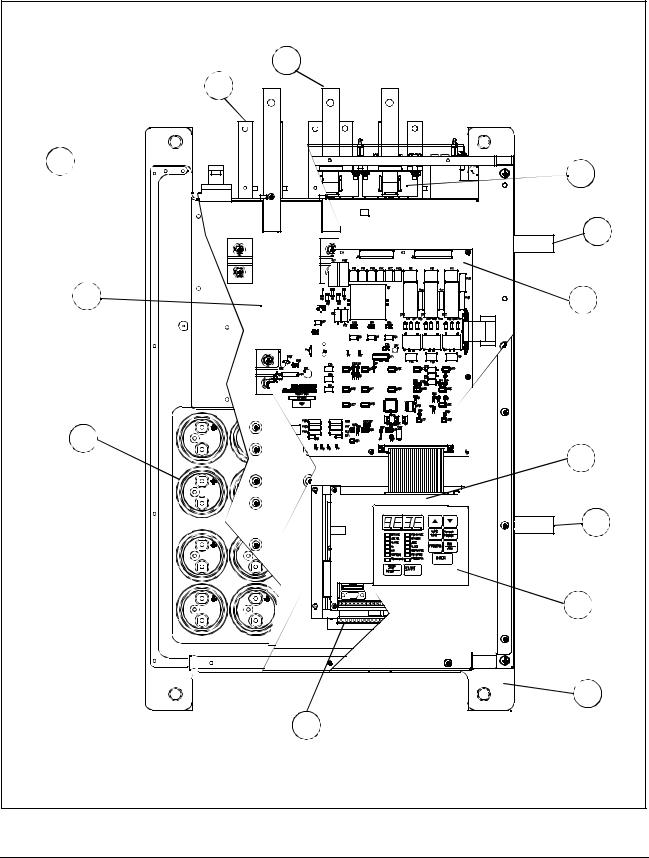
2.3B-Frame LiquiFlo Drive Component Locations
The B-Frame LiquiFlo drives have the following main components. The numbered items listed below provided correspond to the numbers used in figure 2.2. Replacement parts are listed in chapter 9.
1.Bus Bars (3) (AC Output)
2.Bus Bars (6) (AC Input)
3.IGBT Modules
4.Output Laminate
5.Capacitors
6.RMI Board
7.Casting
8.Membrane Switch Keypad
9.Coolant Lines - (a) Inlet, (b) Outlet
10.Regulator Board
11.Power Module Control (PCB)
12.Current Feedback Devices (3)
2-2 |
LiquiFlo AC Power Modules, Hardware Reference Version 6.4 |
|
1 |
|
2 |
3 |
12 |
|
|
|
9b |
4 |
11 |
|
|
5 |
|
|
10 |
|
9a |
|
8 |
|
7 |
|
6 |
Figure 2.2 – B-Frame LiquiFlo Drive Component Locations
About the Drive |
2-3 |

2.4C-Frame LiquiFlo Drive Component Locations
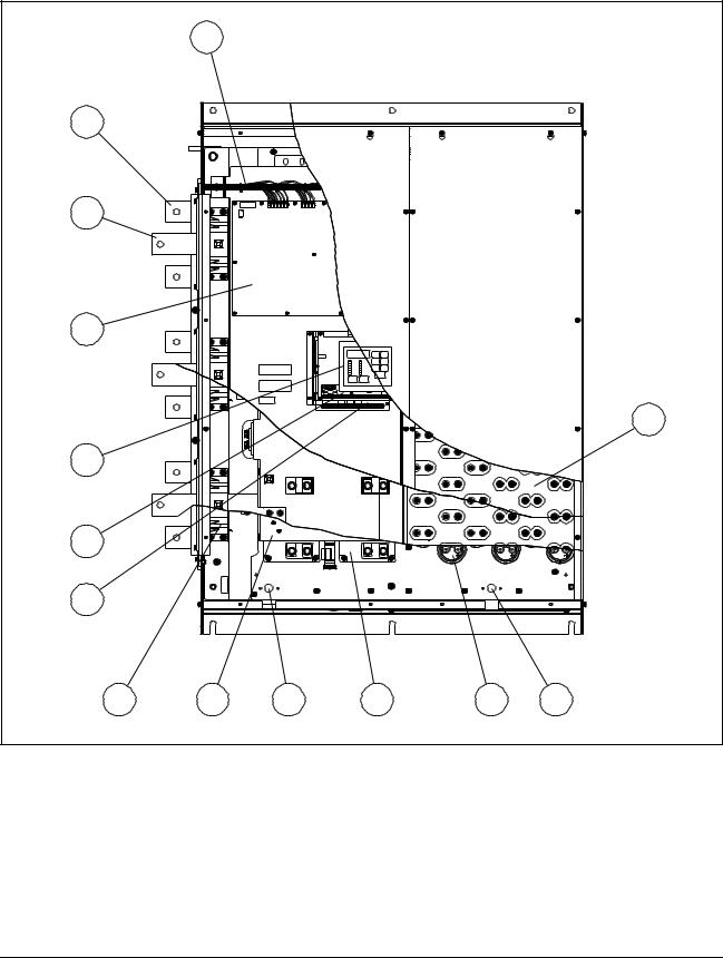
The C-Frame LiquiFlo drives have the following main components. The numbered items listed below provided correspond to the numbers used in figure 2.3. Replacement parts are listed in chapter 9.
1.Bus Bars (AC Input)
2.SCR Bridge (AC to DC Converter)
3.Power Module Adapter Printed Circuit Board (PCB)
4.Power Interface Harness
5.Bus Bars (AC Output)
6.LEM InterfaceHarness
7.DC Bus Control PCB
8.Gate Driver PCB -Low Side
9.DC Bus Laminate Assembly
10.Output Current Feedback Devices
11.IGBT Modules
12.Chillplate (Heatsink)
13.Capacitors
14.Drive Baseplate
15.Reactor (Not Shown)
16.Discharge Resistors (Not Shown)
17.Control Panel Assembly
18.Bus Control - PMA Harness
19.Bus Control - Gate Drive Harness
20.Gate Driver PCBHigh Side (Not Shown)
21.Membrane Switch Keyboard/Bracket
22.Regulator PCB
23.Option Board (Optional)
24.Coolant Lines - (Not Shown)
2-4 |
LiquiFlo AC Power Modules, Hardware Reference Version 6.4 |

|
|
16 |
1 |
|
|
2 |
|
|
3 |
|
|
|
|
17 |
4 |
|
|
5 |
|
|
6 |
|
18 |
|
|
|
7 |
|
19 |
|
|
|
8 |
|
20 |
9 |
|
21 |
|
|
22 |
10 |
|
23 |
|
|
|
11 |
|
|
12 |
|
|
13 |
14 |
|
|
24 |
|
|
15 |
|
|
|
Figure 2.3 – C-Frame LiquiFlo Drive Component Locations
About the Drive |
2-5 |

2.5D-Frame LiquiFlo Drive Component Locations
The D-Frame LiquiFlo drives have the following main components. The numbered items listed below provided correspond to the numbers used in figure 2.4. Replacement parts are listed in chapter 9.
1.Chillplate Harness
2.Bus Bars (AC Input)
3.Bus Bars (AC Output)
4.Power Module Control PCB
5.Membrane Switch Keypad
6.Regulator PCB
7.RMI Option PCB
8.Current Feedback Devices
9.Gate Driver PCB
10.Coolant Connection (Outlet)
11.IGBT Module
12.Capacitors
13.Coolant Connection (Inlet)
14.Output Laminate
2-6 |
LiquiFlo AC Power Modules, Hardware Reference Version 6.4 |
|
1 |
|
|
|
|
2 |
|
|
|
|
|
3 |
|
|
|
|
|
4 |
|
|
|
|
|
|
|
|
|
|
14 |
5 |
|
|
|
|
|
6 |
|
|
|
|
|
7 |
|
|
|
|
|
8 |
9 |
10 |
11 |
12 |
13 |
Figure 2.4 – D-Frame LiquiFlo Drive Component Locations
About the Drive |
2-7 |

2.6Regulator Board Description
LiquiFlo drive regulation is performed by a microprocessor on the Regulator board. See figure 2.5. Drive operation is adjusted by the parameters entered through the keypad. The Regulator board accepts power circuit feedback signals and an external speed reference signal, as well as data from an encoder that is attached to the motor when set up for FVC regulation. The Regulator board provides:
•PWM gating signals to the IGBT power devices
Based on the output of the control loop, the regulator sends PWM gating signals to isolated drivers on the Gate Driver board. These drivers switch the Insulated Gate Bi-polar Transistors (IGBTs), producing a waveform that corresponds to the voltage and frequency outputs of the inner V/Hz, FVC, or SVC regulators. The IGBTs can be switched at either a 2, 4, or 8 kHz carrier frequency.
•Form A and B contacts for drive status indicators
The Form A and B contacts are under control of the user via programmable parameters. A Form A or B transition can indicate drive status. The contacts are rated for 5 amps resistive load at 250 VAC/30 VDC and are made available through the terminal strip.
•Display data for a four-character display and fourteen indicator LEDs
For a description of the keypad/display refer to section 2.6.6. For operational instructions, see the LiquiFlo Software Reference manual (D2-3410).
•An analog output
The analog output is a scaled voltage (0-10 VDC) or current (4-20 mA) signal proportional to either motor speed (RPM), motor torque, or current (%TORQUE). The current signal selection (via jumper J17) requires a power supply for operation. The power can be sourced from the encoder terminals (4 and 9) or from an external 15 V power supply. See table 7.1, terminals 10 and 11, for more information. The analog output signal is available through the terminal strip.
2-8 |
LiquiFlo AC Power Modules, Hardware Reference Version 6.4 |
|
J16 |
60-Pin Ribbon Cable |
|
|
|
|
|
USER DISPLAY |
J3 |
|
|
Cable |
|
|
Ribbon |
|
J9 |
J7 |
|
|
Pin |
|
|
J17 |
J4 |
|
34- |
J8 |
|
|
|
|
|
|
USER I/O TERMINAL STRIP |
J3 |
- |
Option Board Connector |
J9 |
- |
Keypad/Display Connector |
J4 |
- |
Analog Input Jumper |
J16 |
- Power Module Feedback Cable |
|
J7 |
- |
OIM (Optional) Connector |
J17 |
- |
Analog Output Jumper |
J8 |
- |
RS-232C Port |
|
|
|
Figure 2.5 – LiquiFlo Regulator Board Component Locations
About the Drive |
2-9 |
2.6.1 Jumper Locations and Settings
Jumpers J4 and J17 on the Regulator board are factory-set for voltage in and voltage out signals. Refer to figure 2.5 for their locations on the Regulator board. If you need to change the jumpers’ settings, use the following procedures.
ATTENTION: Do not alter the setting of any jumper not described in this instruction manual. Failure to observe this precaution could result in
!damage to, or destruction of, the equipment.
2.6.1.1Setting the Analog Input Speed Reference Jumper (J4)
Jumper J4 is the analog speed/torque (U.000) reference jumper. This jumper selects either +/- 10 VDC or 0-20 mA input. Parameters P.009, P.010, and P.011 are used in conjunction with the jumper.
Note that if the position of jumper J4 is changed after the parameters are programmed, the software will not recognize that the input reference or polarity has been changed. Be sure to verify that parameters P.009, P.010, and P.011 are correct before starting the drive. Refer to the LiquiFlo Software Start-Up and Reference manual for more information.
Use the following procedure to set jumper J4:
ATTENTION: DC bus capacitors retain hazardous voltages after input power has been disconnected. After disconnecting input power, wait five
!(5) minutes for the DC bus capacitors to discharge and then check the voltage with a voltmeter to ensure the DC bus capacitors are discharged before touching any internal components. Failure to observe this precaution could result in severe bodily injury or loss of life.
Step 1. Turn off input power to the drive and wait five minutes.
Step 2. Open the door of the enclosure.
Step 3. Verify that the DC bus voltage is zero by following the procedure in section 9.3.
Step 4. Locate jumper J4 on the Regulator board. Refer to figure 2.5.
Step 5. Locate pin 1 on jumper J4. Move the jumper to the desired setting as shown in figure 2.6.
Step 6. Close the door of the enclosure.
Step 7. Reapply input power.
2-10 |
LiquiFlo AC Power Modules, Hardware Reference Version 6.4 |
Step 8. Verify that Terminal Strip Analog Input Offset (P.009), Terminal Strip Analog Input Gain (P.010), and Terminal Strip Analog Input Configure (P.011) are correctly set. Note that the jumper settings must match the software settings; otherwise, the reference value may differ from what is expected. Refer to the LiquiFlo Software Start-Up and Reference manual for more information.
Voltage Input Option |
Current Input Option |
||||
Pins 2-3 |
Pins 1-2 |
||||
+10 VDC |
0-20 mA |
||||
|
|
|
|
|
|
|
|
|
|
|
|
|
|
|
|
|
|
|
|
|
|
|
|
J4 J4 (default)
Figure 2.6 – Jumper J4 Settings for Analog Input Speed Reference
2.6.1.2Setting the Analog Output Jumper (J17)
Jumper J17 is the analog output jumper. This jumper selects either a 0-10 VDC or 4-20 mA scaled signal output that is programmable to be proportional to either speed or torque using parameter P.012. Refer to the LiquiFlo Software Reference manual for more information about this parameter.
The jumper only selects a 0-10 VDC source voltage or 4-20 mA sink current to represent speed or torque. Note that the 4-20 mA current selection requires a power supply for operation as shown in table 7.8, terminals 10 and 11.
Use the following procedure to set jumper J17:
ATTENTION: DC bus capacitors retain hazardous voltages after input power has been disconnected. After disconnecting input power, wait five
!(5) minutes for the DC bus capacitors to discharge and then check the voltage with a voltmeter to ensure the DC bus capacitors are discharged before touching any internal components. Failure to observe this precaution could result in severe bodily injury or loss of life.
Step 1. Turn off input power to the drive and wait five minutes.
Step 2. Open the door of the enclosure.
Step 3. Verify that the DC bus voltage is zero by following the procedure in section 9.3.
Step 4. Locate jumper J17 on the Regulator board. Refer to figure 2.5.
Step 5. Locate pin 1 on jumper J17. Move the jumper to the desired setting as shown in figure 2.7.
Step 6. Close the door of the enclosure.
About the Drive |
2-11 |

Step 7. Reapply input power.
Step 8. Verify that parameter P.012 is set correctly for either speed or current.
Voltage Output Option |
Current Output Option |
||||
Pins 2-3 |
Pins 1-2 |
||||
+10 VDC |
4-20 mA |
||||
|
|
|
|
|
|
|
|
|
|
|
|
|
|
|
|
|
|
|
|
|
|
|
|
J17 J17 (default)
Figure 2.7 – Jumper J17 Settings for Analog Outputs
2.6.2 Wiring the Regulator Board Terminal Strip
The terminal strip on the Regulator board provides terminals for connecting customer I/O devices. See figures 2.5 and 2.8. The following terminals are provided:
•Terminals 1-3: RS-232 connections
•Terminals 4-9: encoder connections
•Terminals 10-11: analog output connections
•Terminals 12-15: analog speed/torque reference connections
•Terminals 16-25: 24 VDC digital input connections
•Terminal 26: no connection
•Terminal 27: 24 VDC common
•Terminals 28-31: status relay connections
See chapter 7 for a complete description of, and how to wire, all of the signals available through the Regulator board terminal strip.
2-12 |
LiquiFlo AC Power Modules, Hardware Reference Version 6.4 |

RS-232 Tx |
RS-232 Rx |
RS-232 Regulator Common |
+15 VDC |
Phase A |
Phase A Not |
Phase B |
Phase B Not |
Regulator Common |
Analog Meter Output |
Regulator Common |
Isolated Reference Voltage |
VDC Speed Reference |
Ma Speed Reference |
Isolated Reference Gnd |
+24 VDC |
Digital Input 8 (Remote/Local) |
Digital Input 7 (Ramp1/Ramp2) |
Digital Input 6 (Forward/Reverse) |
Function Loss |
Run / Jog |
Reset |
Stop |
Start |
+24 VDC Common |
No Connection |
+24 VDC Common |
N.C. Relay Contact |
N.C. Relay Common |
N.O. Relay Contact |
N.O. Relay Common |
|
|
|
|
|
|
|
|
|
|
|
|
|
|
|
16 |
|
|
|
20 |
|
|
|
|
|
|
|
|
|
|
|
1 |
2 |
3 |
4 |
5 |
6 |
7 |
8 |
9 |
10 |
11 |
12 |
13 |
14 |
15 |
|
17 |
18 |
19 |
|
21 |
22 |
23 |
24 |
25 |
26 |
27 |
28 |
29 |
30 |
31 |
|
|
|
|
|
|
|
|
|
|
|
|
|
|
|
|
|
|
|
|
|
Factory |
|
|
|
|
|
|
|
||
RS-232 |
|
|
Encoder |
|
|
Analog Analog Speed |
Configurable |
|
Installed |
|
|
|
Status Relays |
|||||||||||||||||
|
|
|
|
|
Jumper |
|
|
|
||||||||||||||||||||||
Connections |
Connections |
|
Output |
Reference |
|
|
|
|
|
|
|
|
|
|
|
|
|
|||||||||||||
|
|
|
|
|
|
|
|
|
|
|
|
|
|
|
|
|
||||||||||||||
|
|
|
|
|
|
|
|
|
|
|
|
|
|
|
|
|
|
Digital Inputs |
|
|
|
|
|
|
|
|
|
|||
|
|
|
|
|
|
|
|
|
|
|
|
|
|
|
|
|
(Isolated 24 VDC) |
|
|
|
|
|
|
|
|
|||||
Figure 2.8 – Typical Regulator Board Terminal Strip Connections
2.6.3 RS-232 Communication Port
The Regulator board contains a 9-pin D-shell RS-232 communication port (J8). This port provides RS-232 communication between the LiquiFlo drive and a personal computer running the Control and Configuration (CS3000) software. See figure 2.5. Refer to instruction manual D2-3348 for more information about the CS3000 software.
2.6.4 RMI Board Connector
The flat-ribbon cable connector (J3) on the left side of the Regulator board is a parallel bus connection port that is used on LiquiFlo drives for the Remote Meter Interface (RMI) board.
The RMI board provides an extended set of terminal strip inputs and outputs for the LiquiFlo drive. When the drive control source is the terminal strip (P.000 = rE), the RMI board can be used to provide additional speed reference selections. The RMI board also provides an outer PI regulator that is used to adjust trim. An optional adjustable torque (vector) or current (V/Hz) limit is available using the RMI board's analog or frequency input. See section 2.7 for a more detailed description of the RMI board. Refer to section 7.4 for a detailed description of the RMI terminal strip signals, and how to wire the RMI board.
The J3 connector can also be used to provide a means of attaching optional boards such as the DeviceNet™ Option board, the AutoMax™ Network Option board, or similar boards to the LiquiFlo drive. Note that you must first remove the RMI board before a communication board can be added to the LiquiFlo drive.
About the Drive |
2-13 |
Refer to the appropriate board instruction manual for more information. Refer to section 2.8 of this manual for more information on optional drive kits.
2.6.5 Operator Interface Module Connector
Flat-ribbon connector J7 provides a means of attaching the optional Operator Interface Module (OIM). The OIM is available for use as a remote keypad for the LiquiFlo drive. Refer to the OIM instruction manual (D2-3342) for more information.
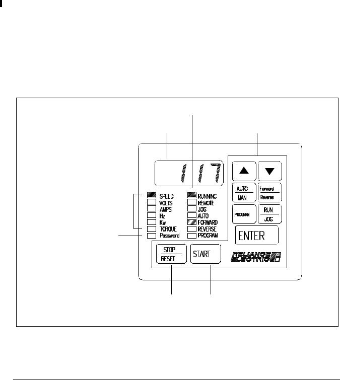
2.6.6 Keypad/Display
The front panel keypad/display is used to program and operate the LiquiFlo drive. See figure 2.9. The four-character display is used to indicate drive parameters, parameter values, and fault codes. The fourteen single LEDs indicate drive status and mode, as well as identifying drive outputs whose values are displayed on the four-character display.
Refer to the LiquiFlo Software Start-Up and Reference manual for more information.
Drive Status LEDs |
|
Display |
Keypad |
Monitor Mode LEDs |
|
Password LED |
|
Stop/Reset |
Start Key |
Key |
|
Figure 2.9 – Keypad/Display |
|
2-14 |
LiquiFlo AC Power Modules, Hardware Reference Version 6.4 |

2.7RMI Board Description
The following signals are available at the RMI board terminal strip. Refer to figure 2.10 for terminal identification. For a detailed description of the RMI board signals, refer to section 7.4.
2.7.1 Digital Inputs
Four 24 volt DC digital inputs provide additional speed reference options. The inputs are active high. A 24 VDC supply is provided by the RMI board for use with the digital inputs. The supply is short circuitand overvoltage-protected.
2.7.2 Digital Outputs
Four 24 volt digital outputs are turned on and off as a result of data comparisons in the drive. All digital outputs are source-driven (active high with common ground) and short circuit-protected. Each output has an adjustable time delay that can be programmed as an on-delay or an off-delay. An option to select an external 24 volt supply for increased current capability at the outputs is jumper-selectable.
2.7.3 Relay Outputs
Three relay outputs can be turned on and off as a result of data comparisons in the drive. Each output has an adjustable time delay that can be programmed as an on-delay or an off-delay. All contacts are rated at 2A, 24VDC or 250VA, 120VAC.
2.7.4 Analog Input
The analog input is based on a 10-bit analog-to-digital (A/D) converter and is jumper-selected between 0 to 10 volts or 0 to 20 mA. Separate connection terminals are provided for voltage input and current input. The inputs are overvoltage-protected. Offset and gain are computed by software.
2.7.5 Analog Outputs
Three analog output channels can be configured. The outputs are short circuit protected. The output value is modulated over four 1 msec scans to provide 10-bit data resolution.
2.7.6 Frequency Input
The frequency input operates from 0 to 200 kHz, 15 VDC. The input is single-ended and uses the same common as the analog input.
About the Drive |
2-15 |
2.7.7 Wiring the RMI Board Terminal Strip
ATTENTION: You are responsible for conforming with all applicable local, national, and international codes. Failure to observe this precaution could
!result in damage to, or destruction of, the equipment.
Refer to figure 2.10 for the signal and control I/O terminal connections on the RMI board. terminal strip connections and related parameters. Refer to section 7.4 for descriptions of, and how to wire, all RMI board terminal strip connections.
Digital Input 1 |
Digital Input 2 |
Digital Input 3 |
Digital Input 4 |
+24 V (for digital inputs only) |
External +24 V Input for Digital Outputs |
Digital Output 1 |
Digital Output 2 |
Digital Output 3 |
Digital Output 4 |
Digital Output Common |
Relay 1 Common |
Relay 1 Normally Open |
Relay 2 Normally Closed |
Relay 2 Common |
Relay 2 Normally Open |
Not Used |
Relay 3 Normally Closed |
Relay 3 Common |
Relay 3 Normally Open |
Not Used |
Analog Input: 0 to 10 V |
Analog Input: 0 (4) to 20 mA |
Analog I/O Common |
Analog Output 1: 0 to 10 V |
Analog Output 2: +/-10 V |
Analog Output 3: 0 to 10 V/0 to 20 mA |
Analog I/O Common |
Frequency Input (Ground = Analog I/O Common) |
41 |
42 |
43 |
44 |
45 |
46 |
47 |
48 |
49 |
50 |
51 |
52 |
53 |
54 |
55 |
56 |
57 |
58 |
59 |
60 |
61 |
62 |
63 |
64 |
65 |
66 |
67 |
68 |
69 |
|
|
|
|
|
|
|
|
Figure 2.10 – Terminal Connections on the RMI Board |
|
|
|
|
|
|
|
|
||||||||||||
2-16 |
LiquiFlo AC Power Modules, Hardware Reference Version 6.4 |

2.8Optional Equipment
Table 2.2 lists standard available LiquiFlo kits and options.
Table 2.2 – Available Kits and Options
|
|
Instruction |
|
Description |
Model Number |
Manual |
|
|
|
|
|
|
2TC3025 |
D2-3305 |
|
|
2TC3075 |
|
|
Motor Encoder Cable |
2TC4025 |
|
|
2TC4075 |
|
|
|
|
|
|
|
|
2TC4100 |
|
|
|
2TC4300 |
|
|
|
|
|
|
DeviceNet Network Option Board |
2DV3000 |
MAN0096-03 |
|
|
|||
|
|
|
|
ControlNet Network Option Board |
2CN3000 |
D2-3390 |
|
|
|
|
|
InterBus-S Network Option Board |
2NB3000 |
49’1333 |
|
|
|||
|
|
|
|
AutoMax Network Option Board with |
2AX3000 |
D2-3308 |
|
762mm (30”) of Cable |
|
|
|
|
|
|
|
Johnson Metasys N2 Option Board |
2MT3000 |
HE-HGV3MT |
|
|
|
|
|
|
2LS3000 |
Horner Electric |
|
Landis and Staefa P1 Option Board |
|
Application 2710 |
|
|
|
Manual |
|
|
|
|
|
Modbus Option Board |
2MB3000 |
MAN0183-02 |
|
|
|
|
|
PROFIBUS Option Board |
2PB3000 |
49’1355 |
|
|
|
|
|
AutoMax RS-232 Adapter Cable |
2CA3001 |
D2-3348 |
|
|
|
|
|
Operator Interface Module (OIM) |
2RK3000 |
D2-3342 |
|
|
|
|
|
CS3000 Control and Configuration |
2CS3000 |
D2-3348 |
|
Software |
|
|
|
|
|
|
|
CS3000 RS-232 Computer Cable |
2CA3000 |
D2-3348 |
|
|
|
|
|
115 VAC Interface Option Board |
2LB3000 |
D2-3376 |
|
|
|
|
|
About the Drive |
2-17 |

2-18 |
LiquiFlo AC Power Modules, Hardware Reference Version 6.4 |
 Loading...